Posted on Leave a comment

EASYDRIVE Inverter M200 User Manual Operation Guide

I. Operation Panel Functions and Basic Settings

1. Operation Panel Function Introduction
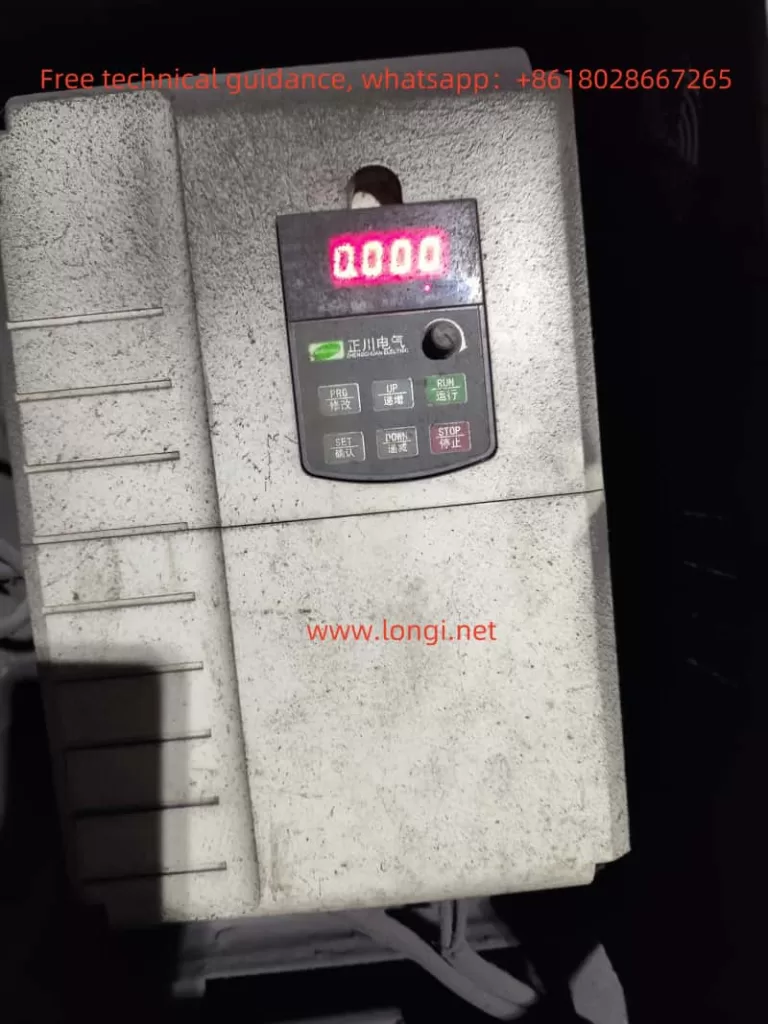
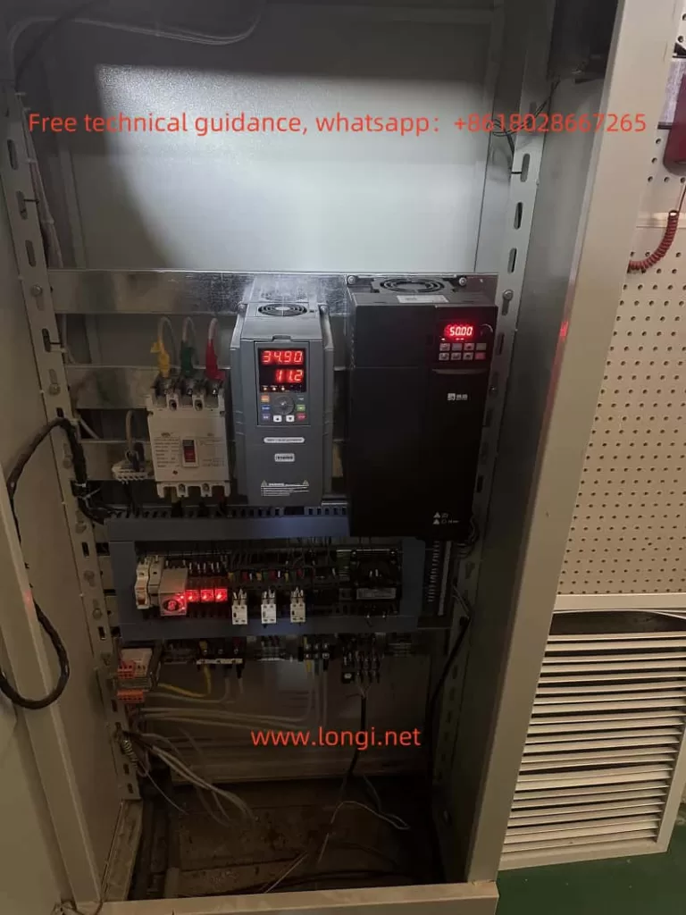
M200 frequency converter displays normally

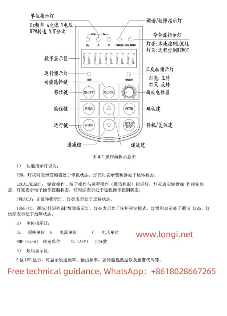
The EASYDRIVE M200 inverter’s operation panel features a straightforward design, incorporating keys such as RUN, M-FUNC (multifunctional), STOP/RESET, PRG (program switch), ENTER, ▲/▼ (data modification), and ▼▼ (data bit switch). The LED display can show set frequency, output voltage, output current, and other parameters.

2. Restoring Factory Defaults

To restore the EASYDRIVE M200 inverter to its factory settings, you can follow these steps via the operation panel:

  • Enter the parameter setting interface (PRG key).
  • Locate the F0-01 parameter (Parameter Initialization).
  • Set F0-01 to 1 and press ENTER to confirm.
  • The inverter will automatically restart and revert to factory settings.
3. Password Setting and Removal

To protect the inverter settings, a user password can be set. The specific operations are as follows:

  • Enter the parameter setting interface.
  • Locate the F0-00 parameter (User Password).
  • Set a non-zero digit as the password and press ENTER to confirm.
  • To remove the password, set F0-00 to 0000.
4. Torque Boost, Cutoff Frequency, and Slip Frequency Compensation Settings
  • Torque Boost Setting:
    • Enter the F1 parameter group and find F1-13 (Torque Boost).
    • Set the torque boost percentage (0.0% to 30.0%) according to the load condition.
  • Cutoff Frequency Setting:
    • Locate F1-14 (Torque Boost Cutoff Frequency).
    • Set the cutoff frequency percentage (0.0% to 50.0%).
  • Slip Frequency Compensation Setting:
    • Enter the F1 parameter group and find F1-15 (V/F Slip Frequency Compensation).
    • Set the slip frequency compensation percentage (0.0% to 200.0%).
E-15

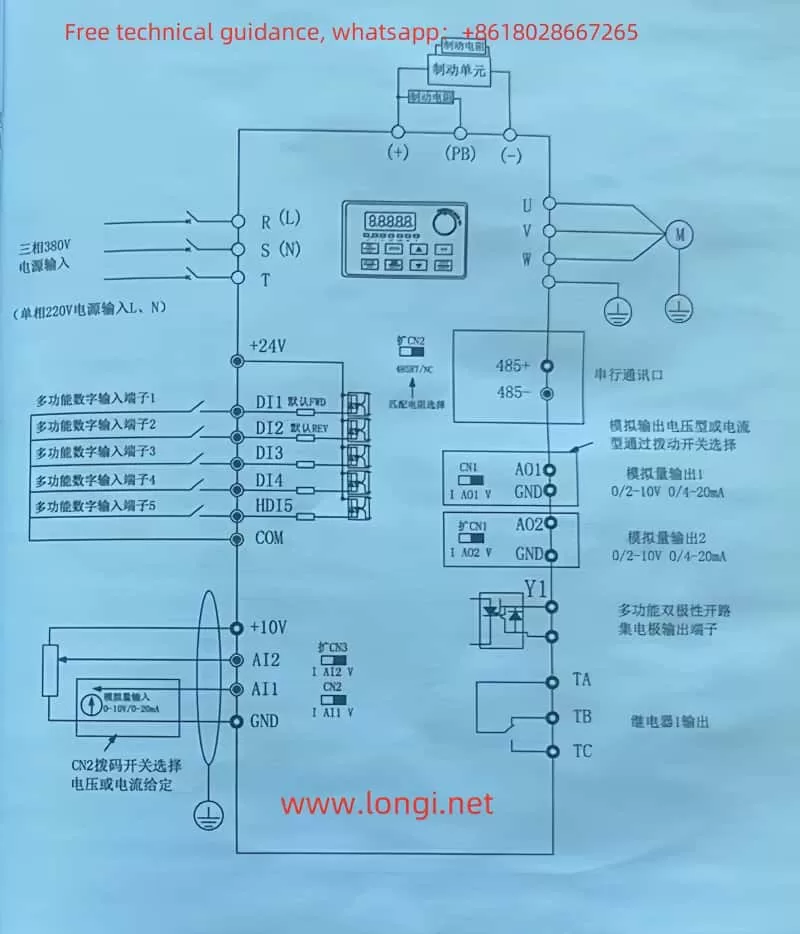
II. Three-Wire Operation Control and External Potentiometer Settings

1. Three-Wire Operation Control

Three-wire operation control allows for forward, reverse, and stop control of the inverter through three terminals. The setup steps are as follows:

  • Enter the F6 parameter group and find F6-09 (FWD/REV Terminal Control Mode).
  • Set F6-09 to 2 or 3 to select the three-wire control mode.
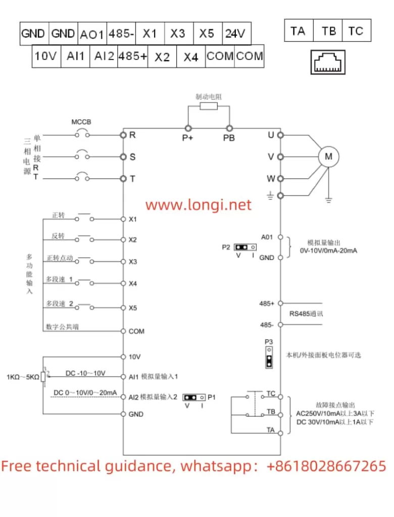
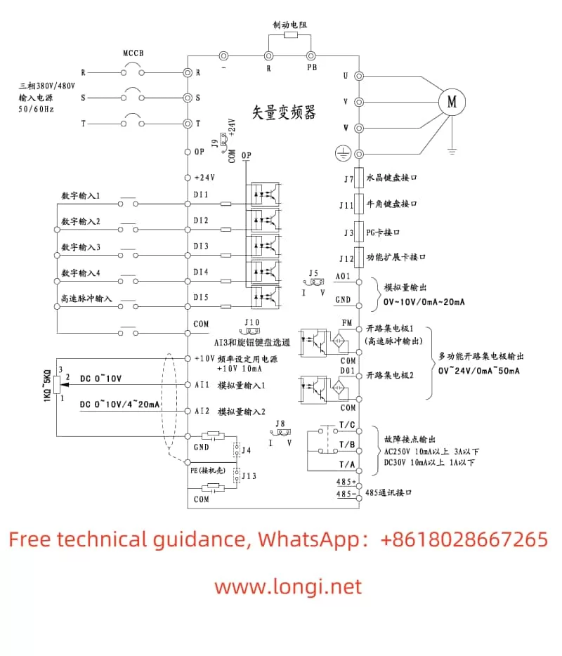
  • When wiring, connect the forward control terminal (e.g., DI1), reverse control terminal (e.g., DI2), and stop control terminal (e.g., DI3) to the corresponding function terminals, respectively.
2. External Potentiometer for Forward/Reverse and Speed Adjustment

An external potentiometer can be used for frequency setting on the inverter, enabling forward/reverse control and speed adjustment. The specific settings are as follows:

  • Forward/Reverse Setting:
    • Enter the F1 parameter group and set F1-02 (Main Frequency Source A Selection) to AI1 or AI2.
    • When wiring, connect the center tap of the external potentiometer to the common terminal of the inverter (e.g., GND), and the other ends to AI1 or AI2 terminals, respectively.
    • Adjust the potentiometer resistance to achieve forward or reverse rotation.
  • Speed Adjustment Setting:
    • Enter the F5 parameter group to set the input range of AI1 or AI2 (F5-00 to F5-03 or F5-05 to F5-08).
    • Wiring is the same as above; adjusting the potentiometer resistance will change the output frequency.

III. Fault Diagnosis and Handling

1. E-015 Fault (External Device Fault)

When the inverter displays the E-015 fault code, it indicates that the external device fault input terminal is closed. The solution is as follows:

  • Check if the external device is functioning normally.
  • Disconnect the external device fault input terminal and clear the fault.
2. Other Common Faults and Solutions
  • E-01 Overcurrent During Acceleration:
    • Possible Causes: Too short acceleration time, excessive load inertia.
    • Solution: Extend the acceleration time, reduce the load inertia.
  • E-02 Overcurrent During Deceleration:
    • Possible Causes: Too short deceleration time, large inertial load.
    • Solution: Extend the deceleration time, reduce the load inertia.
  • E-07 Bus Undervoltage:
    • Possible Cause: Abnormal input voltage.
    • Solution: Check if the power supply voltage is normal.
  • E-16 RS485 Communication Fault:
    • Possible Causes: Improper baud rate setting, serial port communication error.
    • Solution: Set the baud rate appropriately, check the communication cable and ensure the upper computer is working normally.

IV. Conclusion

The EASYDRIVE Inverter M200 User Manual provides a comprehensive operation guide, covering operation panel function introduction, basic settings, terminal control, external potentiometer settings, fault diagnosis, and handling. By reasonably setting parameters and correctly wiring, users can easily achieve various functions of the inverter, ensuring stable equipment operation. Meanwhile, understanding common faults and solutions helps users quickly locate and troubleshoot issues, improving equipment efficiency and reliability.

Posted on Leave a comment

User Manual and Operation Guide for EACON EC5000 Series Frequency Converter

I. Introduction to Operation Panel Functions, Factory Reset, and Password Settings/Removal

The operation panel of the EACON EC5000 series frequency converter from Yikong integrates numerous functions, enabling users to easily configure and monitor the converter. The operation panel mainly comprises an LED display, a potentiometer, and various functional buttons. The LED display clearly shows the current operating status, set parameters, and alarm information, allowing users to monitor and adjust in real-time.

EC5000 physical image

Factory Reset:

  1. Preparation for Parameter Setting: Set the parameters in front of the frequency converter and switch the control mode to the factory reset state.
  2. Select Factory Reset: The display panel on the operation panel will show FXX. Use the up and down buttons to select 1 or 2 and press Enter. The screen will then display F00; press Enter again, and the screen will show F01.
  3. Confirm Reset: In the F01 state, press Enter. The screen will show F00, which is the final step of the factory reset.
  4. Complete Reset: After completing the above steps, press and hold the up and down buttons simultaneously to complete the factory reset.
  5. Reconfigure Parameters: After the factory reset, reconfigure the parameters according to actual requirements and save them.
EC5000 Terminal Block Function Diagram

Password Setting and Removal:

To ensure user and device security, the EACON EC5000 series provides a password setting function.

Password Setting:

  1. Access User Management Interface: On the home page, click the “User Management” menu and enter the initial account password “admin” to access.
  2. Modify Password: Click the “Modify Password” button, enter the original account password “admin”, then enter a new account password and confirm it, and click “Modify”.

Password Removal:

If the user forgets the password, they can reset the device to its factory settings using the reset button on the device. After the factory reset, the password will revert to “admin”. To prevent password theft, it is recommended to regularly change the password and set a relatively complex one.

II. Wiring and Parameter Setting for External Terminal Reversal and External Potentiometer Speed Regulation

EACON Inverter EC5000 Series Standard Wiring Diagram

External Terminal Reversal:

The EACON EC5000 series supports forward and reverse control via external terminals. Specific wiring and parameter settings are as follows:

  1. Wiring:
    • For reverse operation, connect S3, S2, S1, and SC. When the forward/reverse switch stop command (open) is activated, the frequency converter will stop operating.
    • For forward operation, connect the corresponding external switches and terminals as required.
  2. Parameter Setting:
    • No special settings are required; just ensure correct wiring of the external terminals.

External Potentiometer Speed Regulation:

Users can conveniently adjust the output frequency of the frequency converter using an external potentiometer, thereby achieving precise control of motor speed.

  1. Wiring:
    • Connect the output terminal of the external potentiometer to the analog input terminal of the frequency converter (such as the 0-10V or 4-20mA input terminal).
  2. Parameter Setting:
    • Enter the parameter setting interface of the frequency converter and select the corresponding analog input channel (such as FV or FI).
    • Set the corresponding parameters (such as B14 and B15) according to the type of external potentiometer (voltage or current).

III. Fault Code Analysis and Solutions

The EACON EC5000 series features comprehensive fault detection and diagnostic functions, displaying fault codes in real-time to help users quickly locate and resolve faults.

Common Fault Codes and Solutions:

  1. ERR: Indicates a control circuit fault. Possible causes include failure to establish transmission between the digital operator and the drive. Solutions include reinserting the digital operator and connectors, checking the wiring of the control circuit, or replacing the control plug-in board.
  2. Overvoltage, Overcurrent, Overload, etc.: These faults are usually related to the motor’s operating status or external load. Solutions include checking the motor’s operating status, load conditions, and ensuring the frequency converter’s output current and voltage are within specified ranges.
  3. Input/Output Phase Loss Fault: May be caused by poor power or motor wiring. Solutions include checking the power and motor wiring for firmness and reliability.
  4. Overheat Fault: May be caused by overheating of the frequency converter or motor. Solutions include checking if the cooling fan is operating normally, if the ambient temperature is too high, and if additional cooling measures are needed.

By following this guide, users can more effectively utilize the EACON EC5000 series frequency converter, achieving precise motor control and efficient operation. Prompt fault troubleshooting and resolution will improve equipment reliability and stability, extending its service life.

Posted on Leave a comment

User Guide for Marasen M740 Variable Frequency Drive


The Marasen M740 variable frequency drive is a high-performance industrial device widely used for pump control and constant pressure water supply applications. This guide, based on the manual, provides detailed explanations of the operation panel functions, key parameter settings, protective functions, and multi-pump networking operations to help users master the device.

M740 physical picture

1. Operation Panel Functions and Parameter Settings

1. Operation Panel Features

The M740 drive panel includes:

  • LED Display: Shows real-time operating status, current, voltage, and fault codes.
  • Key Functions:
    • Start/Stop Button: Controls the operation of the device.
    • Shift (▲) and Decrease (▼) Buttons: Used for parameter adjustments.
    • Confirm Button: Confirms settings or switches display content.

2. Key Parameters and Codes

The following table provides explanations and configuration methods for key parameter codes:

Pressure Holding Detection Interval (P1.02)

  • Function: Sets the time interval for pressure detection to prevent pressure fluctuations from triggering alarms.
  • Range: 5-120 seconds (recommended: 30 seconds).
  • Default Value: 30 seconds.

Sleep Frequency (P3.01)

  • Function: When the drive output frequency is below the set value for a period, the device enters sleep mode.
  • Range: 0-50 Hz (recommended: 10 Hz).
  • Default Value: 10 Hz.

Water Shortage Detection Mode (P4.01)

  • Function: Sets the logic for detecting water shortage.
  • Options:
    • 0: Disable water shortage detection.
    • 1: Pressure mode.
    • 2: Current mode.
  • Default Value: 1 (Pressure Mode).

Water Shortage Detection Pressure (P4.02)

  • Function: Sets the pressure threshold for water shortage detection in pressure mode.
  • Range: 0-1.0 MPa (adjust based on site needs).
  • Default Value: 0.2 MPa.

Water Shortage Detection Frequency (P4.03)

  • Function: Output frequency during water shortage detection.
  • Range: 0-50 Hz.
  • Default Value: 30 Hz.

Water Shortage Detection Delay (P4.04)

  • Function: Sets the delay time to avoid false alarms.
  • Range: 1-60 seconds.
  • Default Value: 5 seconds.

Water Shortage Detection Current (P4.05)

  • Function: Sets the current threshold for water shortage detection in current mode.
  • Range: 0-50 A.
  • Default Value: 5 A.

M740 Real Panel Diagram

2. Protective Features and Settings

1. Anti-Freeze Function (P5.01)

  • Function: Prevents pipes from freezing during winter to ensure safe operation in low temperatures.
  • Settings:
    • Configure the anti-freeze start temperature (recommended: 5°C).
    • Ensure the external temperature sensor is properly installed.

2. High/Low-Pressure Alarms (P6.01, P6.02)

  • High-Pressure Alarm (P6.01):
    • Function: Prevents damage caused by overpressure.
    • Range: 0-1.0 MPa (recommended: 0.9 MPa).
    • Default Value: 0.9 MPa.
  • Low-Pressure Alarm (P6.02):
    • Function: Alerts the system when water pressure is insufficient.
    • Range: 0-1.0 MPa (recommended: 0.1 MPa).
    • Default Value: 0.1 MPa.

3. Feedback Signal Disconnection Protection (P7.01)

  • Function: Detects signal integrity to prevent malfunction due to sensor or wiring issues.
  • Settings:
    • Enable feedback disconnection protection and configure the alarm logic.

4. Sleep Mode (P3.02)

  • Function: Puts the system into sleep mode under no-load or low-load conditions to save energy.
  • Settings:
    • Sleep Delay: Set the time to enter sleep mode (recommended: 10 minutes).
    • Wake-Up Mode: Triggered by pressure or flow signals.

M740 standard wiring diagram

3. Multi-Pump Networking and Parameter Configuration

The M740 supports a multi-pump networking mode, enabling intelligent switching and cooperative operation.

Usage

  1. Communication Configuration: Connect pumps via the RS485 bus and ensure proper communication.
  2. Master-Slave Pump Switching:
    • Set priority levels for master and slave pumps.
    • Automatically switch based on cumulative runtime.

Key Parameter Configuration

  • Networking Mode (P8.01):
    • Set to “1” (Multi-pump Networking Mode).
  • Switching Time (P8.02):
    • Set to 4-8 hours (adjust as needed).
  • Load Balancing (P8.03):
    • Enable load balancing to extend device lifespan.

4. Fault Codes and Troubleshooting

Below are common fault codes, their meanings, and suggested solutions:

Fault CodeMeaningSolution
E01Motor OverloadCheck load conditions and reduce power.
E02Input Voltage Too LowVerify that the power supply voltage is stable.
E03Output Short CircuitInspect cables for short circuits or grounding issues.
E04Heat Sink OverheatingClean the fan and remove dust from the heat sink.
E05Feedback Signal LostInspect sensors and communication wiring.

For other fault codes not listed, refer to the manual’s appendix section.


With this guide, you can quickly start using the M740 drive and gain expertise in its operations. For further assistance, please consult the complete user manual or contact technical support.

Posted on Leave a comment

User Manual Guide for Sanken SAMCO-vm05 Series Inverter

Basic Settings and Function Adjustments for the Inverter

1. Torque Compensation Function and Startup Mode Configuration

The Sanken SAMCO-vm05 series of inverters offers flexible torque compensation and startup mode settings to meet various operational requirements.

Torque Compensation Function

The torque compensation function allows fine-tuning of the inverter’s output to compensate for variations in motor load and maintain stable operation. To set the torque compensation:

  • Navigate to the function code menu (Cd004).
  • Enter the desired compensation percentage (0-20%). A higher percentage increases the output voltage at low frequencies, enhancing torque output.
Startup Mode Configuration

The startup mode determines how the inverter initiates the motor. To configure the startup mode:

  • Navigate to the function code menu (Cd009).
  • Select the appropriate startup mode:
    • Cd009 = 1: Start from the set startup frequency.
    • Cd009 = 2: Start with speed tracking (for smooth transitions from motor coasting to active control).
    • Cd009 = 3: Apply DC brake before starting from the set startup frequency (useful for loads that may be rotating unexpectedly).
2. Configuring Frequency Parameters

Proper configuration of frequency parameters is crucial for smooth and efficient motor operation.

Startup Frequency (Cd010)

This sets the initial frequency at which the motor begins to accelerate. To set:

  • Navigate to the function code menu (Cd010).
  • Enter the desired startup frequency (0.05-20 Hz).
Run Start Frequency (Cd011)

This sets the minimum frequency required to maintain motor operation. To set:

  • Navigate to the function code menu (Cd011).
  • Enter the desired run start frequency (0-20 Hz). Ensure it is lower than the startup frequency to prevent unintended motor stops.
Lower Limit Frequency (Cd008)

This sets the minimum allowable output frequency. To set:

  • Navigate to the function code menu (Cd008).
  • Enter the desired lower limit frequency (0.05-200 Hz).
Upper Limit Frequency (Cd007)

This sets the maximum allowable output frequency. To set:

  • Navigate to the function code menu (Cd007).
  • Enter the desired upper limit frequency (30-600 Hz, depending on the model).
3. Activating DC Brake and Configuring Related Parameters

The DC brake function helps quickly stop the motor by applying a DC current to the motor windings.

Activating DC Brake

To activate the DC brake:

  • Ensure the DC brake function is enabled in the function code menu (typically defaulted to enabled).
  • Configure the DC brake start frequency (Cd014), brake time (Cd015), and brake strength (Cd016) as required.
Configuring DC Brake Parameters
  • DC Brake Start Frequency (Cd014): Sets the motor speed at which the DC brake engages (0.2-20 Hz).
  • DC Brake Time (Cd015): Sets the duration of the DC brake application (0.1-10 seconds).
  • DC Brake Level (Cd016): Sets the strength of the DC brake (1-10 levels).

By carefully configuring these parameters, you can optimize the performance and reliability of your Sanken SAMCO-vm05 series inverter, ensuring smooth and efficient motor control tailored to your specific application needs.

Posted on Leave a comment

User Guide for SAJ PDG10 Series Inverter

I. Introduction to Operation Panel Functions

1. Panel Display Settings

On the operation panel of the SAJ PDG10 series inverter, you can view the current actual pressure and frequency in real-time. To set the panel to display the current actual pressure and frequency, you can use the “SHIFT” button to cycle through the display options. In the running state, pressing the “SHIFT” button allows you to toggle between running frequency, output current, set pressure, and feedback pressure.

PDG10 frequency converter standard wiring diagram

2. Leakage Coefficient Function and Adjustment

The leakage coefficient (F0.04) is used to adjust issues where the inverter fails to enter sleep mode due to pipeline leakage. When there is leakage in the pipeline, the inverter may not enter sleep mode due to continuous minimal flow. At this point, the leakage coefficient can be adjusted to optimize the sleep function. The greater the leakage, the smaller this coefficient should be set. The default value is 5.0 seconds, with an adjustable range of 0.0 to 100.0 seconds and a minimum adjustment unit of 0.1 seconds.

3. Anti-Freezing and Rust-Proof Function and Settings

The anti-freezing and rust-proof function (F0.03) is used to protect the water pump from damage caused by low temperatures. When this function is enabled, the inverter automatically adjusts the water pump’s operating frequency based on the set parameters to prevent damage from low temperatures. This function has two setting options: timing by seconds or minutes. Simultaneously, the anti-freezing operating frequency (F0.12), anti-freezing operating time (F0.13), and anti-freezing operation interval (F0.14) need to be set.

4. Sensor Channel Selection and Range Setting

The inverter supports two analog input channels (AI1 and AI2) for receiving pressure sensor signals. The sensor channel (AI1, AI2, or the maximum/minimum value between them) can be selected through parameter F0.09. At the same time, parameter F0.08 needs to be set according to the actual pressure sensor range used to ensure that the inverter can correctly interpret sensor signals.

II. Single Pump Control Wiring and Parameter Settings

1. Wiring Instructions

In single pump control scenarios, the inverter wiring is relatively simple. Primarily, the power supply needs to be connected to the R, S, T three-phase power input terminals, the motor to the U, V, W output terminals, and the grounding terminal should be reliably grounded. If external control signals (such as start/stop, fault reset, etc.) are required, the corresponding control wires should be connected to DI1, DI2, and other digital input terminals.

2. Parameter Setting Steps

  • Step 1: Set the sensor range (F0.08) and feedback channel (F0.09).
  • Step 2: Set the pipe network pressure (F0.00) according to actual needs.
  • Step 3: Choose the start mode (F0.05), such as keyboard start, terminal start, or communication control start.
  • Step 4: Set the feedback type for AI1 or AI2 channels (F2.00 or F2.02) based on the sensor type.
  • Step 5: If necessary, further adjust parameters such as acceleration time (F0.18) and deceleration time (F0.19) to optimize water pump performance.
PDG10 frequency converter one to two timed rotation wiring diagram

III. Realization of One-to-Two Timed Alternating Control

1. Wiring Instructions

In one-to-two timed alternating control, an additional power-frequency pump and its control circuit need to be connected. The primary wiring includes connecting the inverter’s output terminals U, V, W to the variable-frequency pump motor, the power-frequency power supply to the power-frequency pump motor, and using contactors and relays to control the circuit to realize the switching between the variable-frequency pump and the power-frequency pump. The specific wiring diagram can be found on page 68 of the manual.

2. Parameter Settings

  • F0.20: Set to 7 to enable one-to-two mode.
  • F1.08: Set to 1 to select alternating variable-frequency pump mode.
  • F0.05: Set to 1 to enable terminal start mode (if communication control start is required, set to 2).
  • F1.09-F1.15: Set parameters such as pump-on pressure deviation, pump-on delay time, pump-off pressure deviation, and pump-off delay time according to actual needs.
  • F3.12 and F3.13: Set the sleep holding frequency and sleep detection frequency to optimize sleep performance.

3. Control Logic

When the pipe network pressure drops below the set value, the inverter first starts the variable-frequency pump and accelerates it. When the variable-frequency pump operates at the upper limit frequency but still cannot meet the pressure demand, it automatically switches to the power-frequency pump. After the set alternation time, the system switches back to the variable-frequency pump, realizing timed alternation control between the two pumps.

IV. Conclusion

The SAJ PDG10 series inverter provides rich functions and flexible parameter setting options to meet the needs of different application scenarios. Through this guide, you can quickly understand the functions of the operation panel, the setting methods for the leakage coefficient and anti-freezing function, the selection and range setting of sensor channels, the wiring and parameter setting steps for single pump control, and the realization of one-to-two timed alternating control. We hope this content will help you better utilize the SAJ PDG10 series inverter products.

Posted on Leave a comment

User Manual Guide for MK-9000 Series Inverters by Minzhong

I. Introduction to Operating Panel Functions and Key Settings

1.1 Introduction to Operating Panel Functions

The operating panel of the Minzhong MK-9000 series inverters is designed to be intuitive and user-friendly, facilitating easy operation and monitoring for users. The following is a detailed introduction to its various functions:

Function diagram of MK-9000 public frequency converter operation panel

Key Components of the Operating Panel:

  • LED Display: Displays various parameters and statuses such as operating frequency, output voltage, output current, etc.
  • Function Buttons:
    • PRG: Enters the parameter setting menu.
    • ENTER: Confirms settings or enters the next menu level.
    • UP/DOWN: Adjusts parameter values or selects menu items.
    • SHIFT: Toggles between different display modes or selects different parameters to adjust.
    • RUN: Starts the inverter.
    • STOP/RES: Stops the inverter or resets fault alarms.
    • MF.K: Multi-function key that can be programmed for different functions such as switching command sources or enabling jogging mode.

1.2 Key Function Settings

1.2.1 Setting Instantaneous Power Failure Continuous Operation (Ride-through Function)

The ride-through function allows the inverter to maintain continuous operation during short-term power outages. To configure this function:

  1. Enter the parameter setting menu by pressing the PRG button.
  2. Use the UP/DOWN buttons to navigate to parameter F1-30 (Instantaneous Power Failure Ride-through Mode).
  3. Adjust the parameter value using the UP/DOWN buttons:
    • 0: Function disabled.
    • 1: Maintain constant bus voltage during power failure.
    • 2: Gradually decelerate and stop during power failure.
  4. Press ENTER to confirm the setting.

1.2.2 Setting Speed Tracking Restart

Speed tracking restart allows the inverter to smoothly restart a motor that is already rotating. To configure this function:

  1. In the parameter setting menu, navigate to F4-00 (Start Mode).
  2. Adjust the parameter value:
    • 0: Direct start.
    • 1: Speed tracking restart.
  3. Press ENTER to confirm the setting.
  4. Optionally, adjust related parameters such as F4-01 (Start Frequency) and F4-04 (Start Frequency Hold Time) to fine-tune the start behavior.

1.2.3 Setting Slip Compensation

Slip compensation improves the speed stability of the motor under load variations. To enable and configure slip compensation:

  1. Navigate to F1-13 (Slip Compensation Gain) in the parameter setting menu.
  2. Adjust the parameter value between 0% and 200% to set the compensation level.
  3. Press ENTER to confirm.
  4. Ensure that the motor’s rated speed (F1-20), rated current (F1-02), and other relevant parameters are correctly set for optimal performance.
MK-9000 public frequency converter labeled wiring diagram

1.2.4 Setting User Password and Restoring Factory Defaults

Setting User Password

To protect your inverter settings from unauthorized access, you can set a user password:

  1. Navigate to FP-00 (User Password) in the parameter setting menu.
  2. Enter the desired password using the UP/DOWN buttons.
  3. Press ENTER to confirm.

Note: After setting a password, you will be prompted to enter it whenever you attempt to modify parameters.

Restoring Factory Defaults

To restore the inverter’s parameters to their factory default settings:

  1. Navigate to FP-01 (Parameter Initialization) in the parameter setting menu.
  2. Adjust the parameter value:
    • 1: Restore factory defaults (except for motor parameters, running time, fault records, and user password).
    • 2: Clear running time and fault records.
    • 3: Reset the power-on timer.
  3. Press ENTER to confirm and apply the changes.

By following these steps, you can effectively utilize the advanced features of the Minzhong MK-9000 series inverters to optimize their performance and reliability in various applications.

Posted on Leave a comment

Guide to Using the Lijia DR300A Inverter User Manual

I. Introduction to Operation Panel Functions and Settings

The operation panel of the Lijia DR300A inverter is its core control unit, providing an intuitive and user-friendly interface. The panel includes multiple function keys and indicator lights for monitoring and controlling the inverter’s operating status.

DR300A operation panel function diagram

1. Password Setting and Keyboard Locking

To ensure device security, the DR300A supports user password protection. To set a password, first enter the parameter setting interface (Group F4), locate the F4.31 parameter item, and set its value to a non-zero value, which will be the user password. To disable password protection, simply reset F4.31 to 0.

The keyboard locking function prevents accidental operation. To enable locking, set the F4.25 parameter item to a non-zero value. To unlock, simultaneously press and hold the “<<” key and the “V” key for more than 2 seconds.

2. Factory Settings Restoration

If you need to restore the inverter parameters to their factory settings, you can set the F0.08 parameter item to “Parameter Restore Mode 1” or “Parameter Restore Mode 2”. The former does not include analog input/output offset parameters, while the latter does. Additionally, you can choose to “Clear Historical Information” to delete fault records and other historical data.

3. Macro Setting Selection

The DR300A offers multiple application macros to meet different needs. To select the “Power Winch Application Macro”, for example, navigate to the F0.04 parameter item and set its value to 6. This will automatically configure the inverter to meet the specific control requirements of power winch equipment.

II. Terminal Start, Forward/Reverse Control, and Speed Adjustment Settings

1. Terminal Start and Forward/Reverse Control

The DR300A supports external terminal start and control of motor forward/reverse rotation. First, set the F0.05 parameter item to 1 (External Terminal Control). Then, connect external switches or relays to the corresponding terminals (e.g., FWD for forward rotation, REV for reverse rotation) to control the motor’s running direction.

2. External Potentiometer Speed Adjustment

To adjust motor speed via an external potentiometer, set the speed reference to analog input. Navigate to the F0.08 parameter item and select AI0, AI1, or AI2 as the speed source. Next, connect the external potentiometer to the corresponding analog input terminal (AI0, AI1, or AI2) and GND. Additionally, set parameters such as F2.15 to F2.20 according to the potentiometer’s output range to match the potentiometer’s minimum/maximum input voltage with the inverter’s speed range.

III. Fault Code Analysis and Resolution

The DR300A inverter features comprehensive fault diagnosis capabilities, enabling real-time monitoring and reporting of device status. When a fault occurs, the “ALM” indicator light on the panel will illuminate, along with the corresponding error code.

1. Common Fault Codes

  • Err.01: Inverter Unit Protection, possible causes include overcurrent, overheating, etc. Solutions include checking motor load, cooling conditions, and cable connections.
  • Err.05: Acceleration Overcurrent, possibly caused by motor stall or excessive load. Check for motor and mechanical blockages, adjust the load, or increase acceleration time.
  • Err.13: Communication Fault, check the communication line, baud rate, and address settings for correctness.

2. Fault Troubleshooting Steps

  • Initial Check: Confirm that the power supply is normal and there are no short circuits or open circuits.
  • Parameter Review: Check that relevant parameter settings are correct, such as acceleration time, deceleration time, motor parameters, etc.
  • Equipment Inspection: Observe whether the motor runs smoothly and listen for any abnormal noises or vibrations.
  • Log Analysis: Review the inverter’s fault records to analyze historical fault information and pinpoint the root cause of the problem.
Lijia frequency converter DR300A series standard wiring diagram

IV. Conclusion

The Lijia DR300A Inverter User Manual is an important reference for operating and maintaining this equipment. By mastering the operation panel functions, properly setting parameters, and quickly diagnosing faults, you can ensure efficient and stable operation of the inverter. Both beginners and experienced engineers can benefit from the practical guidance and assistance provided in the manual. In practical applications, it is recommended to flexibly configure and optimize settings based on specific equipment conditions and actual needs to achieve the best control effects.

Posted on Leave a comment

User Guide for XFC500 Series Manual of Xichi Inverter

I. Introduction to User Panel Functions and Settings

Function diagram of Xichi frequency converter XFC500 series operation panel

1. Access Privileges and User Password Settings

The Xichi Inverter XFC500 series offers different levels of access privileges to protect user parameters from unauthorized modification. Through the operation panel, users can enter the parameter setting menu and select the “b0-03” function code to set the parameter modification attribute. Options include “0: Modifiable” and “1: Not Modifiable”. Additionally, users can set a user password by configuring the “b0-05” function code to protect parameters from being modified by unauthorized personnel. To clear the password, simply set “b0-05” to “0”.

2. Parameter Initialization

When users need to restore factory settings, they can achieve this by setting the “b0-01” function code. Options include “0: No Operation”, “1: Restore Factory Parameters (excluding motor parameters and GP type settings)”, and “2: Clear Record Information”. Selecting “1” will restore the inverter to its factory default settings, but motor parameters and GP type settings will remain unchanged.

3. PWM-related Parameter Settings

PWM (Pulse Width Modulation) parameters significantly impact the operating performance of the inverter. Users can adjust the carrier frequency by setting the “C0-03” function code, with a range of 0.5kHz to 16.0kHz. A lower carrier frequency may increase motor noise and current harmonics, while a higher carrier frequency may increase inverter losses and temperature rise. Furthermore, the “C0-04” function code allows users to enable automatic carrier frequency adjustment based on temperature to avoid overheating.

II. Realization of Terminal Forward/Reverse and External Potentiometer Speed Regulation

1. Terminal Forward/Reverse Function

To achieve the forward/reverse function of the inverter, users need to correctly set the multifunction digital input terminals. Typically, forward rotation can be set by configuring the “F1-00” function code to “1: Forward Run (FWD)”, and reverse rotation to “2: Reverse Run (REV)”. During wiring, connect the forward control signal to the corresponding digital input terminal (e.g., DI1) and the reverse control signal to another digital input terminal (e.g., DI2).

2. External Potentiometer Speed Regulation

External potentiometer speed regulation is usually achieved through analog input terminals. Users can select “F0-01” function code to set the main frequency source to “AI1” (Analog Input 1). During wiring, connect the sliding contact of the external potentiometer to the AI1 terminal, and the fixed contacts to the GND terminal of AI1 and the common terminal of the inverter (e.g., COM terminal). Additionally, the input curve of AI1 needs to be set through function codes such as “F1-25” to “F1-28” to determine the correspondence between the potentiometer position and the output frequency.

XFC500 series standard wiring diagram for Xichi frequency converter

III. Fault Code Meaning Analysis and Solutions

1. Err09: Undervoltage Fault

When the inverter detects that the input voltage is below the set value, it will report an Err09 fault. Solutions include checking whether the input power supply is normal, whether the voltage is stable, and whether the cable connections are reliable.

2. Err11: Motor Overload

The Err11 fault typically indicates that the motor is overloaded. Users should check whether the motor is operating under overload conditions, whether the load exceeds the motor’s rated capacity, and whether there is any jamming in the transmission mechanism.

3. Err15: External Fault

The Err15 fault indicates that the external fault input terminal has been activated. Users should check whether the external fault signal source is normal and whether the wiring is reliable. If the external fault signal is a false operation, the relevant circuits and components should be checked.

IV. Conclusion

The XFC500 Series Manual of Xichi Inverter provides users with detailed operation instructions and parameter setting methods. By reasonably setting access privileges and user passwords, users can protect inverter parameters from unauthorized modification. By correctly setting PWM parameters, terminal forward/reverse, and external potentiometer speed regulation functions, users can achieve precise control over the inverter. Additionally, the manual provides detailed analysis and solutions for fault codes, helping users quickly locate and resolve issues. Overall, the manual is well-structured, logically clear, and an essential reference for users to operate and maintain the inverter.

Posted on Leave a comment

VAIDNOR VDF750 Series General Inverter User Manual Guide

I. Introduction to Operation Panel Functions and Basic Settings

1.1 Introduction to Operation Panel Functions

The VAIDNOR VDF750 series inverter is equipped with an intuitive and user-friendly LED operation panel for function code operation, status monitoring, and control. The main functions of the operation panel include:

  • RUN Indicator: Indicates whether the inverter is currently running.
  • LO/RE (Run Command) Indicator: Indicates the current run control source (panel, terminal, or communication).
  • FWD/REV (Forward/Reverse) Indicator: Indicates the current rotation direction of the motor.
  • TUNE/TC (Tuning/Torque Control/Fault) Indicator: Indicates the current torque control mode or fault status.

Through function keys on the operation panel such as the Programming Key (PRG), Enter Key (ENT), Increment Key (+), and Decrement Key (-), users can conveniently modify parameters, monitor status, and control the inverter.

VDF750 Operation Panel Function Diagram

1.2 Parameter Initialization

Initializing parameters can restore the inverter settings to the factory defaults. The specific operation steps are as follows:

  1. Power On: Ensure the inverter is correctly wired and powered on.
  2. Enter Parameter Setting Interface: Press the PRG key to enter programming mode, and use the Increment or Decrement keys to select the PP group parameters.
  3. Set Parameter Initialization: Set PP-01 to 1 and press the ENT key to confirm. At this point, the inverter’s parameters will be restored to the factory settings (excluding motor parameters).

1.3 Self-Learning Operation

The self-learning operation allows the inverter to automatically acquire the electrical parameters of the controlled motor to improve control accuracy. The specific operation steps are as follows:

  1. Motor Load Disconnection: If possible, disconnect the motor from the load to ensure that the motor can rotate freely without load.
  2. Select Self-Learning Mode: Set P1-37 to 2 (asynchronous motor dynamic complete tuning) or 3 (asynchronous motor static complete tuning) and press the ENT key to confirm.
  3. Start Self-Learning: Press the RUN key on the operation panel, and the inverter will automatically drive the motor to perform the tuning operation, stopping automatically upon completion.

1.4 Setting and Eliminating Passwords

To protect parameters from being modified casually, a user password can be set.

  • Setting Password: Set PP-00 to a non-zero value (1-65535) and press the ENT key to confirm.
  • Eliminating Password: Reset PP-00 to 0 and press the ENT key to confirm, which will eliminate the password.
VAIDNOR VDF750 series inverter wiring diagram

II. Forward/Reverse Start/Stop and External Potentiometer Speed Adjustment Settings

2.1 Wiring Instructions

To achieve forward/reverse start/stop and external potentiometer speed adjustment, it is necessary to correctly wire the control terminals of the inverter. The specific wiring is as follows:

  • Forward Start: Connect the external forward button or relay contact to the DI1 terminal (positive) and the COM terminal (negative).
  • Reverse Start: Connect the external reverse button or relay contact to the DI2 terminal (positive) and the COM terminal (negative).
  • Stop: Connect the external stop button or relay contact to the DI3 terminal (positive) and the COM terminal (negative).
  • External Potentiometer Speed Adjustment: Connect the center tap of the external potentiometer to the AI1 terminal, one end to the +10V terminal, and the other end to the GND terminal.

2.2 Parameter Settings

  • Run Command Selection: Set P0-02 to 1 (terminal control).
  • DI Terminal Function Settings:
    • Set P4-00 to 1 (DI1 for forward operation).
    • Set P4-01 to 2 (DI2 for reverse operation).
    • Set P4-02 to 9 (DI3 for fault reset).
  • AI Terminal Function Settings:
    • Set P0-03 to 2 (AI1 analog input).

III. Fault Code Analysis and Solutions

3.1 Fault Code Analysis

The VAIDNOR VDF750 series inverter has comprehensive fault diagnosis functions. When a fault occurs, the inverter will display the corresponding fault code. The following are some common fault codes and their possible causes:

  • Err02: Acceleration overcurrent. Possible causes include output circuit short circuit, motor stall, or improper parameter settings.
  • Err03: Deceleration overcurrent. Possible causes include damaged braking resistors, too short deceleration time, or excessive load inertia.
  • Err04: Constant speed overcurrent. Possible causes include motor overload, improper parameter settings, or external interference.
  • Err05: Acceleration overvoltage. Possible causes include excessive input voltage, improper deceleration time settings, or lack of braking resistors.

3.2 Solutions

  • Check Peripheral Circuits: Confirm that the motor and cables are correctly connected and there are no short circuits or open circuits.
  • Adjust Parameters: Adjust parameters such as acceleration/deceleration time and braking resistors based on the load conditions.
  • Check Braking Resistors: Ensure that the braking resistors are correctly connected and not damaged.
  • External Environment Check: Eliminate external interference sources such as electromagnetic interference.

IV. Conclusion

The VAIDNOR VDF750 series inverter user manual provides detailed operation guides and parameter setting methods. By correctly understanding and applying the knowledge in the manual, users can easily perform functions such as inverter initialization, self-learning operation, password setting and elimination, forward/reverse start/stop, and external potentiometer speed adjustment. Additionally, the manual provides comprehensive fault code analysis and solutions to help users quickly locate and resolve issues, ensuring stable operation of the inverter.

Posted on Leave a comment

Lingshida Inverter LSD-B7000 Series User Manual Usage Guide

I. Introduction

The Lingshida LSD-B7000 series inverter is a high-performance, multi-functional full-vector variable frequency drive widely used in various industrial control fields. To help users better understand and utilize this inverter, this article will provide a detailed explanation of its panel functions, parameter settings, external wiring, fault code handling, and more.

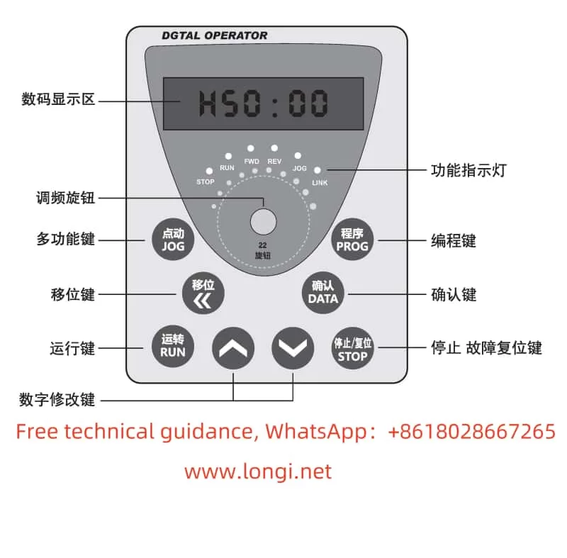
Lingshida frequency converter LSD-B7000 operation panel function diagram

II. Panel Function Introduction

The Lingshida LSD-B7000 series inverter features a clean and intuitive panel design with reasonably laid out function keys for easy operation. The main function keys include:

  • RUN Button: Starts the inverter.
  • STOP Button: Stops the inverter.
  • PROG Button: Enters or exits programming mode for modifying and viewing parameters.
  • ▲▼ Buttons: Used to increase or decrease parameter values in programming mode.
  • DATA Button: Confirms parameter settings and saves them.

Additionally, the panel is equipped with LED indicators to display the inverter’s operational status and fault information.

III. Parameter Settings

  1. Selecting the Appropriate V/F Curve

The V/F curve represents the relationship between the output voltage and frequency of the inverter. Selecting the right V/F curve is crucial for ensuring stable motor operation. The LSD-B7000 series inverter offers multiple preset V/F curves. Users can choose based on the motor type and load characteristics by adjusting the Pr015 parameter in programming mode.

  1. Setting Maximum Frequency, Maximum Voltage, Minimum Frequency, Minimum Voltage, Intermediate Voltage, and Intermediate Frequency
  • Maximum Frequency: Sets the highest output frequency of the inverter, adjustable through the Pr016 parameter.
  • Maximum Voltage: Sets the highest output voltage, adjustable through the Pr017 parameter.
  • Minimum Frequency: Prevents motor overheating at low speeds by setting the lowest output frequency, adjustable through the Pr022 parameter.
  • Minimum Voltage: Ensures stable motor operation at low speeds by setting the lowest output voltage, adjustable through the Pr023 parameter.
  1. Setting Intermediate Voltage and Intermediate Frequency

Adjusting the intermediate voltage and frequency can optimize the inverter’s performance. Users can set two intermediate frequency points and their corresponding voltage values by modifying the Pr018 to Pr021 parameters.

  1. Setting UP/DOWN Frequency Given Function

The UP/DOWN function allows users to manually adjust the output frequency of the inverter using the ▲▼ buttons on the panel. Enable and adjust this function by modifying the Pr060 and Pr061 parameters in programming mode.

  1. Jogging Speed Adjustment

Jogging is a temporary method for adjusting the output frequency. Set the jogging frequency by modifying the Pr058 parameter and press the JOG button on the panel to achieve jogging speed adjustment.

IV. External Wiring and Parameter Settings

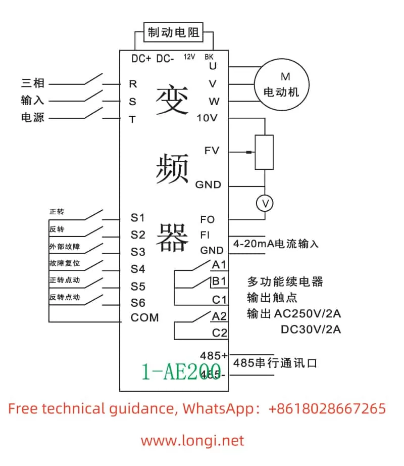
  1. External Terminal Forward/Reverse Control

To achieve forward/reverse control via external terminals, connect the forward (FR) and reverse (RR) terminals. In programming mode, select the external terminal control mode by adjusting the Pr005 parameter and set the Pr141 and Pr142 parameters for forward and reverse functions.

  1. External Potentiometer Speed Control

External potentiometer speed control is a commonly used speed adjustment method. Connect the output end of the potentiometer to the frequency given terminal (e.g., FV terminal) of the inverter. Users can adjust the output frequency of the inverter by rotating the potentiometer. In programming mode, select the external analog voltage given mode by adjusting the Pr004 parameter and set the corresponding FV terminal parameters (e.g., Pr152 and Pr153) to adjust the gain and offset.

Lingshida inverter LSD-B7000 standard wiring diagram

V. Fault Code Meaning Analysis and Solutions

The Lingshida LSD-B7000 series inverter features comprehensive fault protection. When a fault occurs, the inverter displays the corresponding fault code. Below are some common fault codes, their meanings, and solutions:

  • OC: Overcurrent Protection. May be caused by motor overload or output short circuit. Solutions include checking motor load, output circuit, and parameter settings.
  • OV: Overvoltage Protection. May be due to excessive input voltage or damaged brake resistor. Solutions include checking input voltage and brake resistor.
  • LU: Undervoltage Protection. May be due to low input voltage. Solutions include checking input power supply and voltage stabilizer.
  • EF: External Fault. May be caused by abnormal external input signals. Solutions include checking external input terminals and signal sources.

When encountering a fault code, users should first make a preliminary judgment based on the code’s meaning, then follow the solutions to inspect and repair. If the problem persists, contact Lingshida’s after-sales service center for further technical support.

VI. Conclusion

The Lingshida LSD-B7000 series inverter is a powerful and easy-to-use full-vector variable frequency drive. Through this guide, users can better understand and utilize this inverter, mastering its panel functions, parameter settings, external wiring, and fault code handling. In practical applications, users should set parameters and wire connections based on actual needs, regularly perform maintenance and inspections to ensure the long-term stable operation of the inverter.