I. Introduction to Operation Panel Functions and Password & Parameter Lock Settings
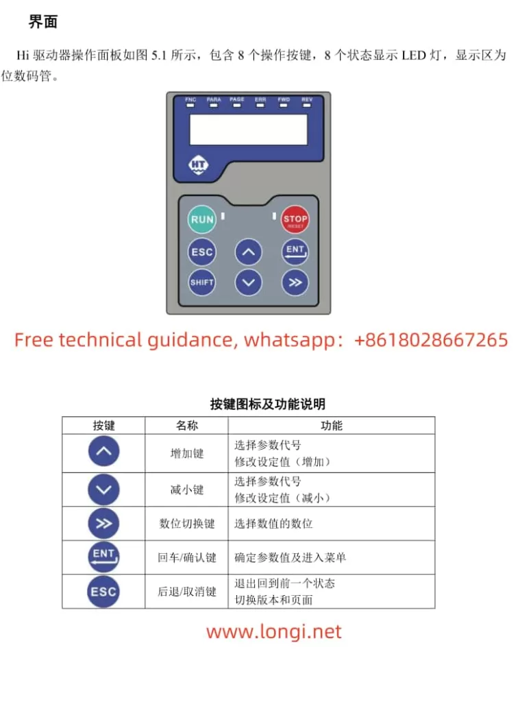
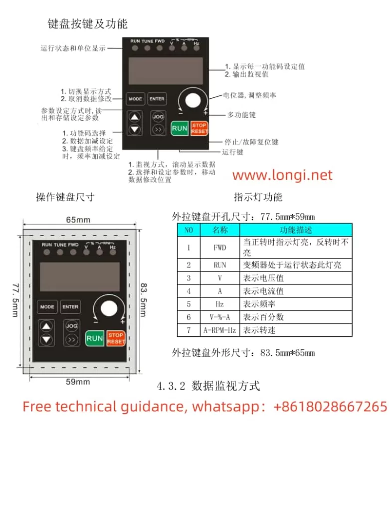
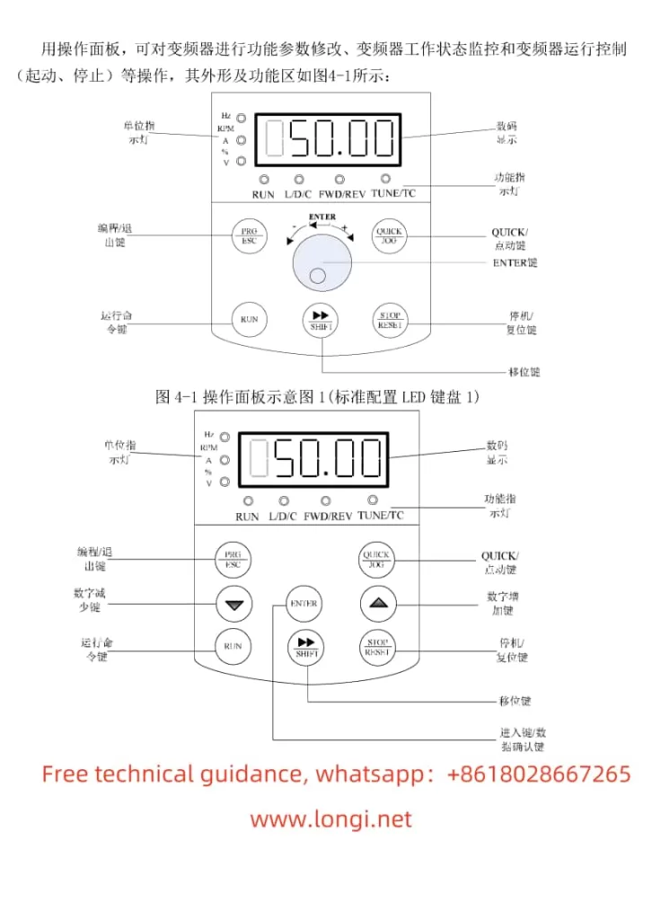
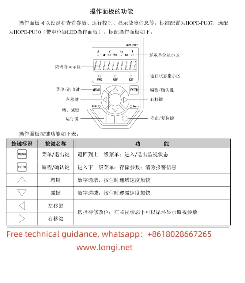
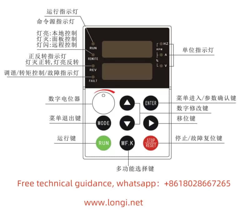
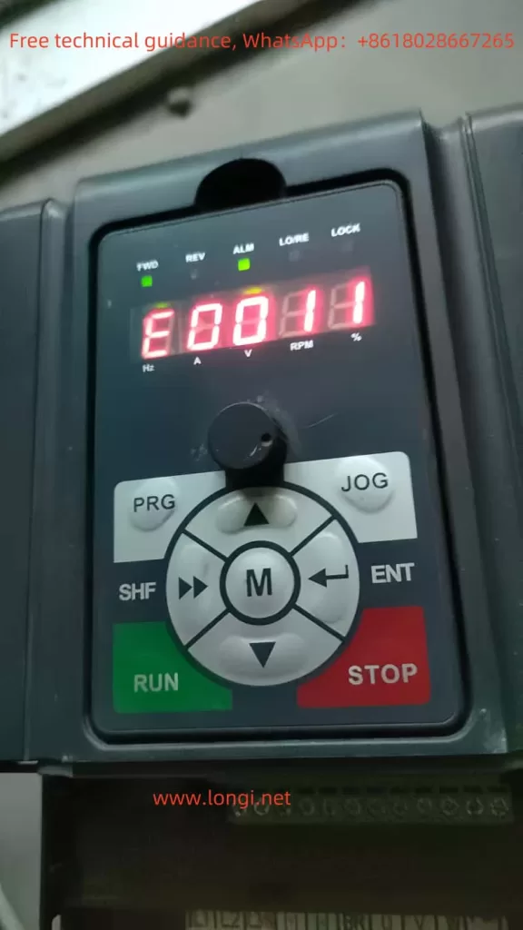
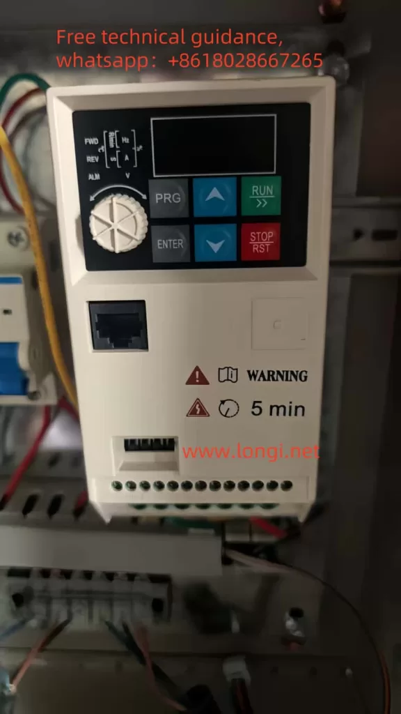
The BoPusen Inverter PER640 series boasts an intuitive operation panel that provides users with a clear interface. The panel primarily comprises a display screen, buttons (such as PRG, ENTER, WARNING, etc.), and status indicators. Users can utilize these buttons and the display screen to set various parameters, monitor operating status, and troubleshoot issues.
Setting Passwords and Parameter Locks:
- Password Setting: Function code F0.23 allows users to set a password within the range of 0~9999. Once set, unauthorized users will be unable to modify the inverter’s parameters.
- Parameter Lock: Function code F8.05 is used for parameter initialization. Selecting “1” will restore the inverter to its factory settings, resetting all user parameters to their default values. This can also be considered a form of parameter lock, ensuring parameters are not changed arbitrarily.
Parameter Initialization:
- Initialization Procedure: By selecting “1” in function code F8.05, users can restore the inverter’s parameters to their factory settings. Selecting “2” will clear fault records.
II. Terminal Forward/Reverse Control and External Potentiometer Speed Regulation
Terminal Forward/Reverse Control:
- To achieve forward/reverse control of the inverter, users need to set function code F0.12 (Operation Direction Setting). This parameter has three options: 0 for forward rotation, 1 for reverse rotation, and 2 to prohibit reverse rotation.
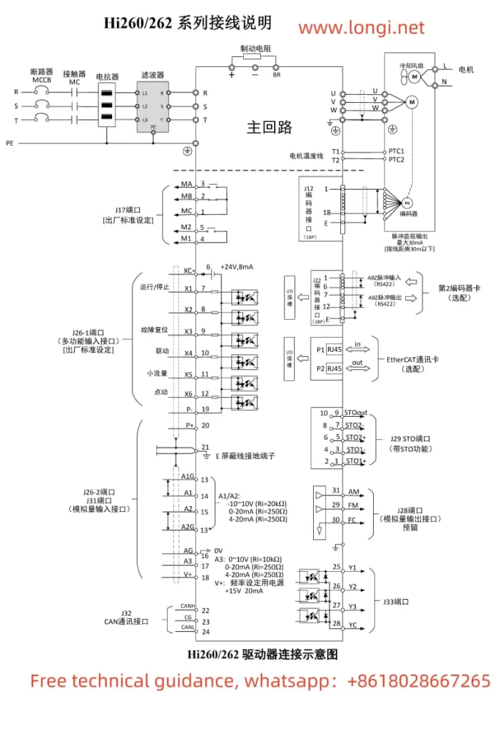
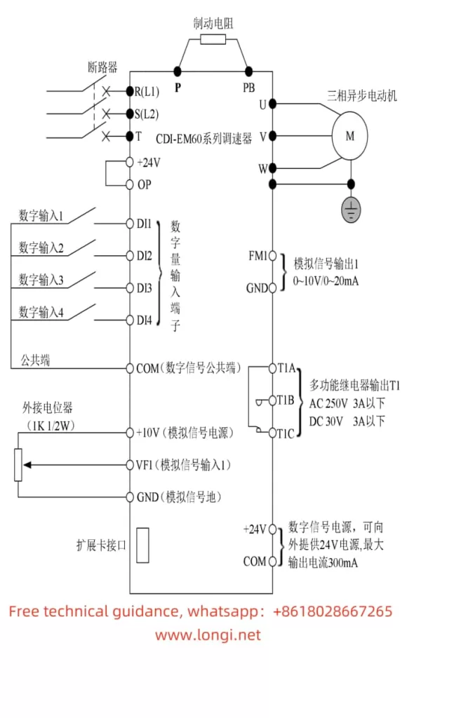
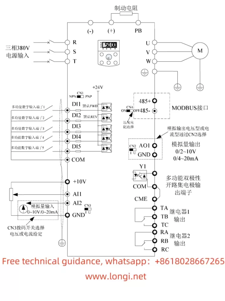
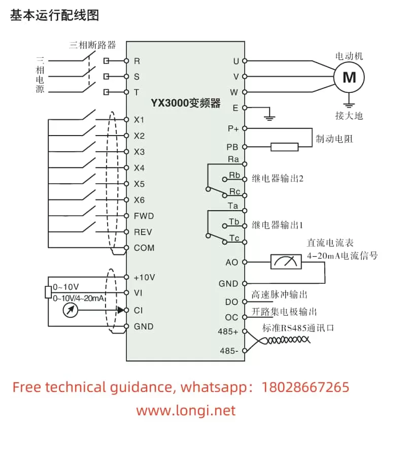
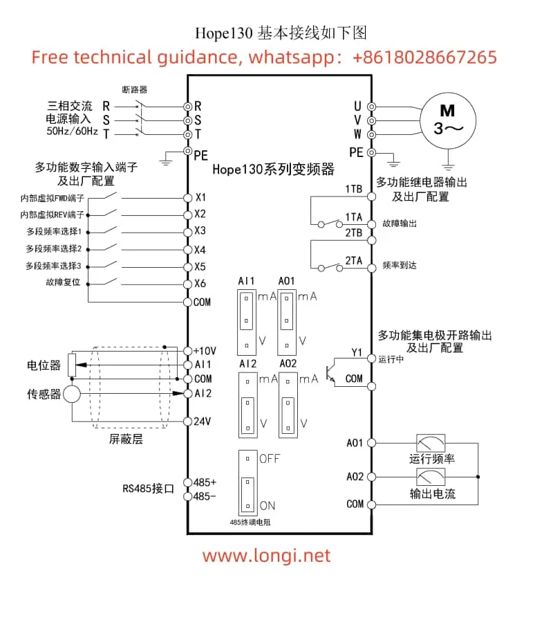
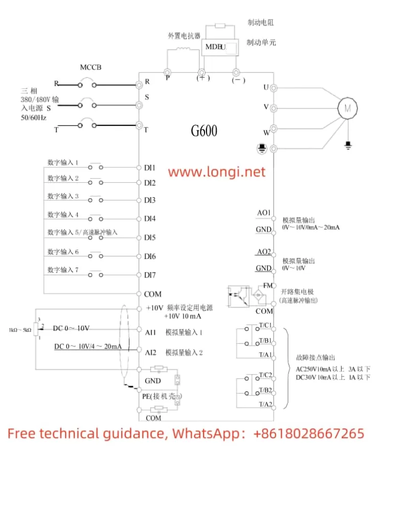
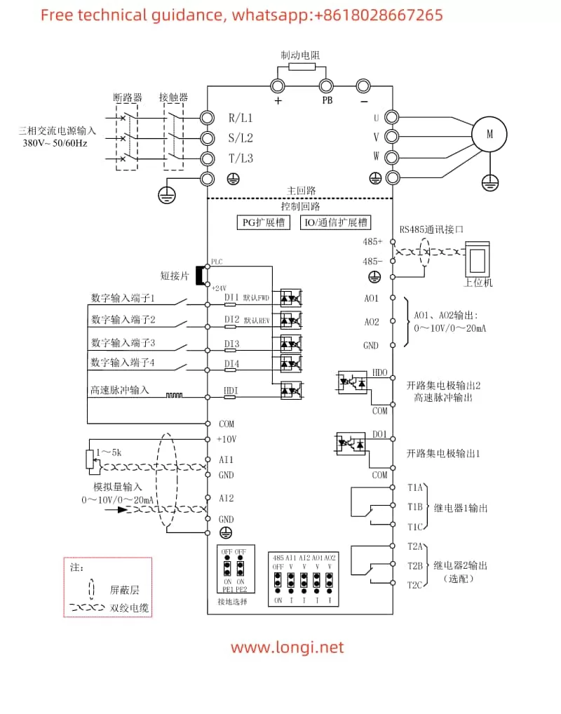
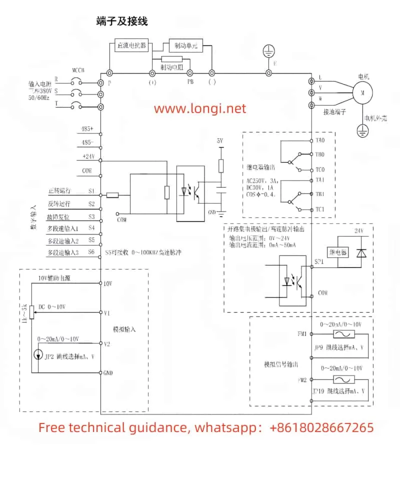
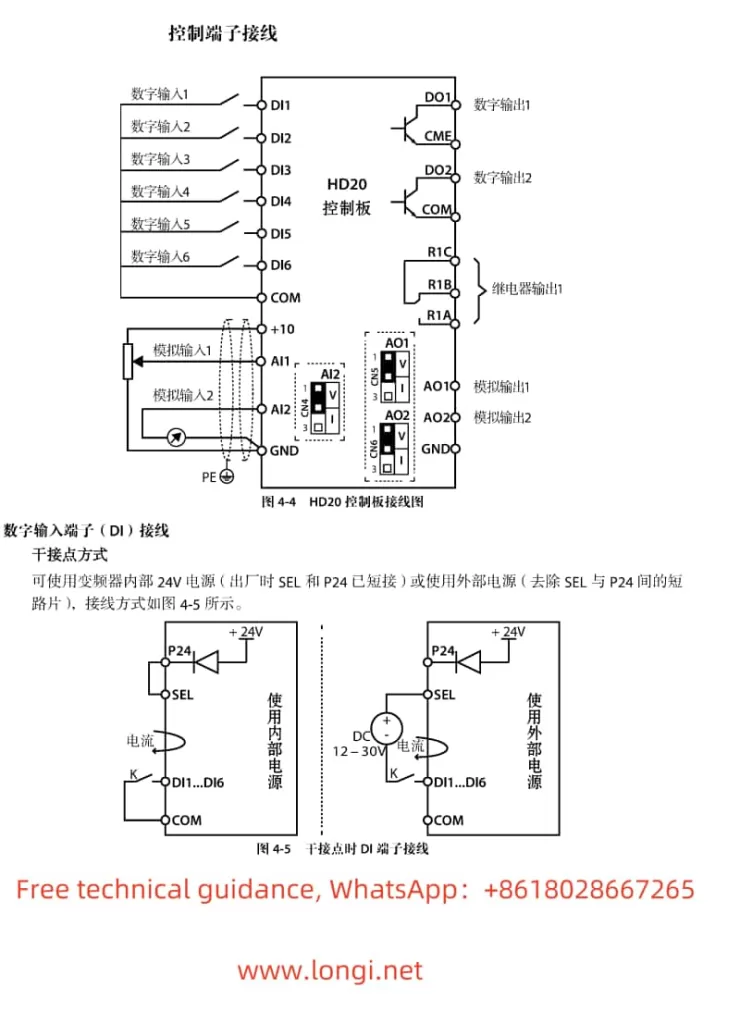
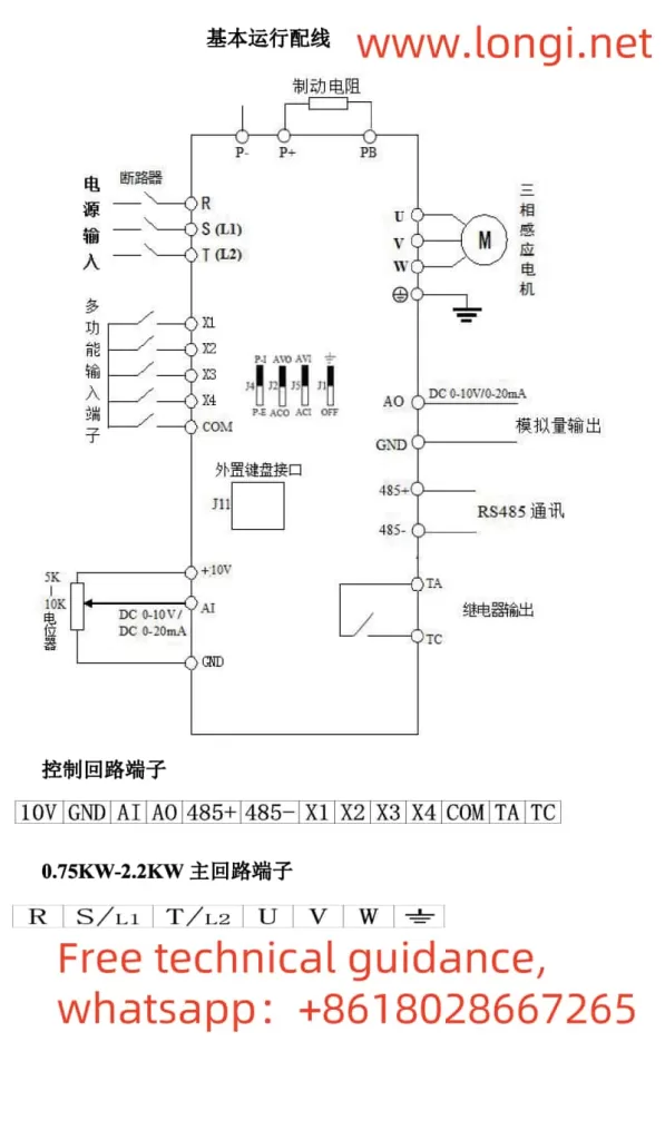
- For wiring, terminals X1 and X2 are typically used for forward/reverse control. Connect terminal X1 to the forward signal source and terminal X2 to the reverse signal source to enable forward/reverse control.
External Potentiometer Speed Regulation:
- To achieve speed regulation via an external potentiometer, users must first set function code F0.03 (Frequency Setting Selection) to “3” (AI Analog Setting).
- For wiring, connect the output terminal of the external potentiometer to the inverter’s AI terminal (typically the AVI terminal), ensuring the GND terminal is grounded. By adjusting the resistance of the external potentiometer, users can change the inverter’s output frequency, thereby achieving speed regulation.
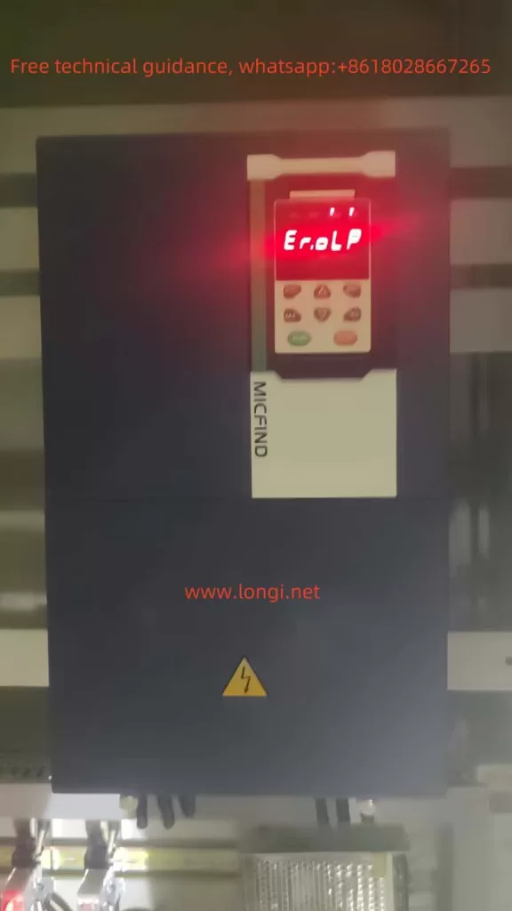
III. Fault Codes and Troubleshooting Methods
The BoPusen Inverter PER640 series provides a comprehensive list of fault codes to assist users in quickly locating and resolving issues. Below are some common fault codes, their meanings, and corresponding troubleshooting methods:
- EOC1 (Overcurrent During Acceleration):
- Meaning: The inverter experiences an overcurrent during the acceleration process.
- Troubleshooting: Extend the acceleration time (F0.10), check if the inverter power is too small, and adjust the V/F curve or torque boost.
- EOC2 (Overcurrent During Deceleration):
- Meaning: The inverter experiences an overcurrent during the deceleration process.
- Troubleshooting: Extend the deceleration time (F0.11), check if the inverter power is too small, and adjust the V/F curve or torque boost.
- EOL1 (Inverter Overload):
- Meaning: The inverter’s output current exceeds the rated value, causing an overload.
- Troubleshooting: Extend the acceleration time (F0.10), select a more powerful inverter, adjust the V/F curve and torque boost, and check if the grid voltage is too low.
- EHU1 (Overvoltage During Acceleration):
- Meaning: The inverter experiences an overvoltage during the acceleration process.
- Troubleshooting: Check if the input power supply is normal and set the starting mode to DC brake start for restarting rotating motors.
- ELUO (Undervoltage During Operation):
- Meaning: The inverter’s input voltage falls below the allowable range.
- Troubleshooting: Check if the power supply voltage is normal and seek assistance from the manufacturer.
- ESC1 (Power Module Fault):
- Meaning: The inverter’s power module has failed.
- Troubleshooting: Seek assistance from the manufacturer.
IV. Conclusion
The BoPusen Inverter PER640 series user manual provides users with a detailed operation guide, covering the introduction to operation panel functions, password and parameter lock settings, methods for achieving terminal forward/reverse control and external potentiometer speed regulation, as well as fault codes and troubleshooting methods. By carefully reading the manual and following the instructions, users can fully utilize the inverter’s capabilities, ensuring stable equipment operation. Additionally, the manual provides abundant technical parameters and wiring diagrams, offering users strong technical support.