Posted on Leave a comment

SANJ INVERTER PDG10 Series Water Pump Control Dedicated Usage Guide

I. Achieving Constant Pressure Water Supply with Single Pump Control

In single pump control mode, the PDG10 series SANJ INVERTER automatically adjusts the speed of the water pump motor by setting the pipe network pressure value, thereby maintaining a constant water supply pressure. Below are the steps to achieve constant pressure water supply:

1. Wiring

  • Main Circuit Wiring: Connect the three-phase power supply to the R, S, T terminals of the inverter and the motor to the U, V, W terminals, ensuring the grounding terminal is reliably grounded.
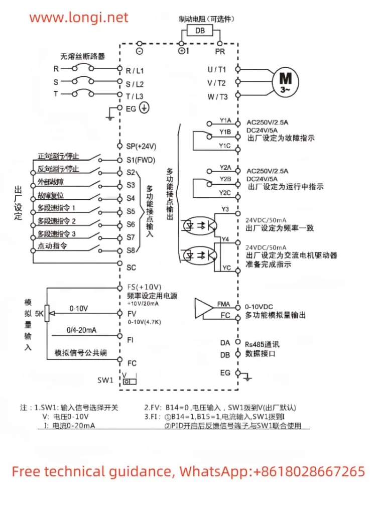
  • Control Circuit Wiring: Depending on requirements, connect the pressure sensor to the AI1 or AI2 terminal and set the F2.00 or F2.02 parameter according to the sensor type. If using external start/stop control, connect the start and stop signals to the DI1 and DI2 terminals.

2. Parameter Settings

  • Pressure Setting: Set the target pressure value through the F0.00 parameter. For example, to achieve a pipe network pressure of 3.0 kg, set F0.00=3.0.
  • Start Mode: If using external start/stop control, set F0.05=1 (terminal start/stop).
  • Sensor Settings: Set F0.08 (sensor range), F0.09 (sensor feedback channel selection), and F2.00 or F2.02 (sensor feedback type selection) according to the pressure sensor type.
  • Operating Mode: Set F0.15=0 to select the constant pressure control mode.
  • Other Parameters: Set acceleration time (F0.18) and deceleration time (F0.19) parameters according to actual needs.

II. One-to-Two Timed Rotation Control

In one-to-two timed rotation control mode, one inverter alternately controls two water pump motors to achieve timed rotation. Below are the implementation steps:

1. Wiring

  • Main Circuit Wiring: Connect the output terminals of the inverter to the U, V, W terminals of the two water pump motors respectively.
  • Control Circuit Wiring: Connect the pressure sensor to the AI1 or AI2 terminal and connect the relay output terminals of the inverter (e.g., T1A/T1B and T2A/T2B) to the control circuit of the contactors to achieve water pump rotation control.
  • Frequency Control: If frequency backup is required, connect the frequency power supply to the corresponding contactor and control the contactor’s engagement and disengagement through the inverter’s relay output.

2. Parameter Settings

  • One-to-Two Mode: Set F0.20=7 to select the one-to-two mode.
  • Rotation Mode: Set F1.08=1 to select the rotating variable frequency pump mode.
  • Pump Addition and Reduction Parameters: Set F1.09 (bias pressure for adding frequency pump), F1.10 (delay time for adding frequency pump), F1.11 (bias pressure for reducing frequency pump), F1.12 (delay time for reducing frequency pump), etc., according to actual needs.
  • Rotation Time: Set F1.05 to define the interval time for timed rotation of the main and auxiliary pumps.
  • Other Parameters: Set PID parameters (e.g., F3.00 proportional gain, F3.01 integral time) and other related parameters according to actual needs.

III. Multi-Pump Networking Scheme

The PDG10 series SANJ INVERTER supports multi-pump networking control via RS485 (MODBUS) or CAN bus. Below are the implementation steps:

1. Wiring

  • RS485 Communication Wiring: Connect the A+/B- terminals of the inverter to the RS485 communication ports of the host computer or other inverters using twisted pair or shielded cable.
  • CAN Communication Wiring: Connect the S+/S0/S- terminals of the inverter to the CAN communication ports of other inverters using twisted pair or shielded cable.

2. Parameter Settings

  • Communication Parameters: Set F8.00 (local address), F8.01 (RS485 communication baud rate setting), F8.02 (RS485 data format setting), etc., to ensure normal communication between inverters.
  • Multi-Pump Networking Mode: Set F0.20 (multi-pump macro debugging function) to select the corresponding multi-pump networking mode (e.g., master, slave, etc.).
  • Network Mode: Set F1.02 (multi-pump network mode selection) to define the network role of each inverter (e.g., master, slave, etc.).
  • Slave Settings: Set F1.00 (multi-pump networking communication address) on the slave to ensure each slave has a unique address.
  • Other Parameters: Set the number of multi-pump networking slaves (F1.03), multi-pump operation mode (F1.04), etc., according to actual needs.

IV. Fault Codes and Solutions

The PDG10 series SANJ INVERTER features comprehensive fault protection functions. When a fault occurs, the corresponding fault code will be displayed. Below are some common fault codes, their meanings, and solutions:

  • E002: Overcurrent during acceleration. Possible causes include too fast acceleration, low grid voltage, or undersized inverter. Solutions include increasing acceleration time, checking the input power supply, or selecting a larger inverter.
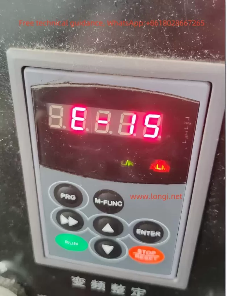
  • E015: External fault. Possible causes include activation of the external fault input terminal. The solution is to check whether the external device input is normal.
  • E027: Water shortage alarm. Possible causes include abnormal water pressure/level, disconnected or poorly contacted sensors, etc. Solutions include checking the water inlet pressure of the water pump, sensor installation and wiring, and related parameter settings.
  • E050: Multi-pump communication error. Possible causes include abnormal multi-pump communication or duplicate networking addresses. Solutions include power cycling, checking CAN networking communication address settings, or seeking service support.

When a fault occurs, first refer to the fault code to identify the possible cause and follow the corresponding solution. If the problem cannot be resolved, contact a professional technician for further inspection and repair.

Summary

The PDG10 series SANJ INVERTER, as a dedicated product for water pump control, features powerful functionality, easy operation, and high reliability. Through reasonable wiring and parameter settings, it can achieve various application modes such as single-pump constant pressure water supply, one-to-two timed rotation control, and multi-pump networking control. Additionally, the inverter provides comprehensive fault protection functions and fault code prompts, facilitating fault diagnosis and handling for users. It is hoped that this usage guide will help users better understand and use the PDG10 series SANJ INVERTER.

Posted on Leave a comment

LCGK (ZTV) Inverter LC400E Series Manual Operation Guide

I. Introduction

The LCGK (ZTV) LC400E series high-performance vector inverter boasts remarkable performance and flexible control functions, making it widely applicable in textile, paper, wire drawing, machine tools, packaging, food processing, fans, pumps, and other automated production equipment. This article aims to provide users with a detailed operation guide for the LC400E series inverter, covering panel function introductions, parameter initialization, password setting and removal, terminal start/stop operations, external potentiometer speed adjustment, and fault code analysis and troubleshooting methods.

ATV INVERTER operation panel function diagram

II. Inverter Panel Function Introduction

The LC400E series inverter is equipped with an intuitive and user-friendly operation panel. The primary function keys include the Programming Key (PRG), Enter Key (ENTER), Increment Key (Δ), Decrement Key (∨), Run Key (RUN), Stop/Reset Key (STOP/RES), and Multi-Function Key (MF.K). These keys allow users to easily modify parameters, monitor operating status, and control the inverter.

  • Programming Key (PRG): Used to enter or exit the function parameter settings interface.
  • Enter Key (ENTER): Used to confirm parameter settings or enter the next menu level.
  • Increment Key (Δ) and Decrement Key (∨): Used to modify parameter values or select function codes.
  • Run Key (RUN): Used to start the inverter.
  • Stop/Reset Key (STOP/RES): Used to stop the inverter or reset fault alarms.
  • Multi-Function Key (MF.K): Achieves different function switches based on the P7-00 parameter setting.

III. Parameter Initialization and Password Setting

Parameter Initialization

Parameter initialization restores all inverter parameters to their factory default settings. This function is useful when clearing user-defined settings or troubleshooting parameter errors. The specific operation steps are as follows:

  1. Enter the function parameter settings interface (press the PRG key).
  2. Find and modify the PP-01 parameter, setting it to 01 (restore factory parameters, excluding motor parameters) or 02 (clear record information).
  3. Press the ENTER key to save the settings and exit the parameter settings interface.

Password Setting and Removal

To prevent unauthorized modification of inverter parameters, users can set a password. The steps for setting and removing the password are as follows:

  • Password Setting:
    1. Enter the function parameter settings interface.
    2. Modify the PP-00 parameter, setting it to a non-zero value (the password).
    3. Press the ENTER key to save the settings.
  • Password Removal:
    1. Enter the function parameter settings interface.
    2. Set the PP-00 parameter to 0.
    3. Press the ENTER key to save the settings.
LCGK INVERTER LC400E Wiring Diagram

IV. Terminal Start/Stop and External Potentiometer Speed Adjustment

Wiring Terminals

To achieve terminal start/stop and external potentiometer speed adjustment, it is necessary to correctly wire the control terminals of the inverter. Commonly involved terminals include digital input terminals (DI1, DI2, etc.), analog input terminals (AI1, AI2, etc.), and run control terminals (such as RUN, STOP, etc.).

Parameter Settings

  1. Terminal Start/Stop:
    • Set the P0-02 parameter to 1 to select the terminal command channel.
    • According to requirements, set DI1, DI2, and other digital input terminals to forward rotation (P4-00=1), reverse rotation (P4-01=2), and stop (e.g., P4-02=3 for the stop terminal in three-wire operation control).
  2. External Potentiometer Speed Adjustment:
    • Set AI1 or AI2 terminals as analog input terminals to receive speed adjustment signals from an external potentiometer.
    • Set the P0-03 parameter to the corresponding analog input source (e.g., AI1 or AI2).
    • Adjust parameters such as P3-01 (torque boost) and P3-02 (torque boost cutoff frequency) as needed to achieve better speed adjustment performance.

V. Fault Code Meaning Analysis and Troubleshooting Methods

During operation, if the LC400E series inverter encounters a fault, it will immediately stop outputting and display the corresponding fault code. Users can quickly locate the problem and take corresponding measures based on the fault code. Below are the meanings and troubleshooting methods for some common fault codes:

  • Err01 (Inverter Unit Protection): Possible causes include output circuit short circuit, module overheat, etc. Solutions include checking and eliminating peripheral faults, cleaning the air duct, replacing the fan, etc.
  • Err02 (Acceleration Overcurrent): Possible causes include too short an acceleration time, low voltage, etc. Solutions include increasing the acceleration time, adjusting the voltage to the normal range, etc.
  • Err03 (Deceleration Overcurrent): Similar to acceleration overcurrent, possible causes include too short a deceleration time, low voltage, etc. Solutions include adjusting the deceleration time and voltage accordingly.
  • Err04 (Constant Speed Overcurrent): Possible causes include sudden load changes during operation, undersized inverter selection, etc. Solutions include eliminating sudden load changes, selecting an inverter with a higher power rating, etc.

In addition, there are various other fault codes, such as Err05 (Acceleration Overvoltage), Err06 (Deceleration Overvoltage), Err07 (Constant Speed Overvoltage), etc. Each fault code corresponds to specific possible causes and solutions. When encountering a fault, users should first refer to the fault information list in the manual for troubleshooting.

VI. Conclusion

The LCGK (ZTV) LC400E series high-performance vector inverter provides users with efficient and reliable automation solutions through its powerful functions and flexible control methods. Through this operation guide, users can better understand and use this series of inverters to achieve more precise and stable control effects. In practical applications, users should also consider specific application scenarios and requirements, reasonably set parameters, and regularly perform maintenance to ensure the long-term stable operation of the inverter.

Posted on Leave a comment

ENC INVERTER EDS1000 User Manual Usage Guide

I. Introduction to Inverter Panel Functions

The ENC INVERTER EDS1000’s panel integrates various control functions, allowing users to easily start, stop, and adjust the speed of the inverter. The main keys on the panel include:

ENC INVERTER EDS1000 Operation Panel Function Diagram
  • RUN: Forward operation key. Pressing this key will start the inverter to run forward at the set frequency.
  • STOP/RESET: Stop/Reset key. In normal operation, pressing this key will stop the inverter’s output; in fault mode, pressing this key will reset the inverter.
  • REV JOG: Reverse/Jog key. Depending on the setting of parameter F0.03, this key can be used as a reverse operation key or a jog operation key.
  • Analog Potentiometer: Used to manually adjust the inverter’s output frequency by rotating it, enabling speed control.

Steps to Achieve Panel Start/Stop and Speed Adjustment:

  1. Start the Inverter: Press the RUN key, and the inverter will start running at the currently set frequency and direction.
  2. Stop the Inverter: Press the STOP/RESET key, and the inverter will stop outputting.
  3. Speed Adjustment: Rotate the Analog Potentiometer on the panel to adjust the inverter’s output frequency in real-time, thereby achieving speed control.

II. Guide to Using the Simple PLC Function

The EDS1000 inverter provides a simple PLC function, allowing users to set different stages and corresponding times to automatically adjust the frequency and direction of the inverter within a cycle.

Terminal Connections:

  • FWD: Forward control terminal.
  • REV: Reverse control terminal.
  • COM: Common terminal, used in conjunction with the FWD or REV terminal.
  • X1-X8: Multifunctional input terminals, which can be used to set different stage controls.
ENC INVERTER EDS1000 Series Wiring Diagram

Parameter Settings:

  1. F4.00: Simple PLC operation settings. Select the operation mode as needed (e.g., stop after a single cycle, continuous cycle, etc.).
  2. F4.01-F4.14: Set the frequency, direction, and operation time for each stage. For example, F4.01 sets the frequency and direction for the first stage, and F4.02 sets the operation time for the first stage.

Implementation Steps:

  1. Set the frequency, direction, and operation time for each stage through the F4 group parameters based on actual requirements.
  2. Connect the FWD and REV terminals to the corresponding control signals to control the forward and reverse rotation of the inverter.
  3. Connect the X1-X8 multifunctional input terminals as needed to trigger different stages.
  4. Start the inverter, and the simple PLC function will automatically adjust the inverter’s frequency and direction according to the set stages and times.

III. Setting the Swing Frequency Function

The swing frequency function is a special variable frequency operation mode that periodically varies the output frequency of the inverter within a certain range by setting parameters such as swing frequency amplitude and period.

Parameter Settings:

  • F6.00: Swing frequency function selection. Set to 1 to enable the swing frequency function.
  • F6.01: Swing frequency operation mode. Select the swing frequency input mode (automatic or manual) and amplitude type (variable amplitude or fixed amplitude).
  • F6.02: Swing frequency amplitude. Set the amplitude of the swing frequency.
  • F6.03: Jump frequency. Set the jump frequency at the start of swing frequency.
  • F6.04: Swing frequency period. Set the time for one complete cycle of swing frequency.

Setting Steps:

  1. Set parameter F6.00 to 1 to enable the swing frequency function.
  2. Set parameter F6.01 as needed, selecting the swing frequency operation mode and amplitude type.
  3. Set parameter F6.02 to determine the amplitude of the swing frequency.
  4. Adjust the jump frequency and swing frequency period by setting parameters F6.03 and F6.04 as needed.
  5. Start the inverter, and the swing frequency function will operate according to the set parameters.

IV. Fault Codes and Handling Methods

The EDS1000 inverter provides extensive fault codes to help users quickly locate and resolve faults. Below are some common fault codes, their meanings, and handling methods:

  • E001: Overcurrent during inverter acceleration. Possible causes include too short an acceleration time, an inappropriate V/F curve, etc. Handling methods include extending the acceleration time, adjusting the V/F curve, etc.
  • E002: Overcurrent during inverter deceleration. Possible causes include too short a deceleration time, potential energy load or large inertia load, etc. Handling methods include extending the deceleration time, increasing external energy dissipation braking components, etc.
  • E008: Inverter overload. Possible causes include too short an acceleration time, excessive DC braking, etc. Handling methods include extending the acceleration time, reducing the DC braking current, etc.
  • E010: Inverter overheat. Possible causes include blocked air ducts, excessively high ambient temperature, etc. Handling methods include cleaning the air ducts, improving ventilation conditions, etc.
  • E013: Inverter module protection. Possible causes include instantaneous overcurrent of the inverter, phase-to-phase or ground short circuit in the output three-phase, etc. Handling methods include checking and reconnecting wires, replacing damaged components, etc.

When the inverter encounters a fault, users should first check the possible causes based on the fault code and troubleshoot according to the provided handling methods. If the issue cannot be resolved, users should promptly contact the manufacturer or a professional technician for assistance.

Conclusion

The ENC INVERTER EDS1000 User Manual provides a detailed usage guide, covering panel function introductions, simple PLC function usage, swing frequency function settings, and fault code handling methods. By carefully reading the manual and following the guide, users can fully leverage the inverter’s capabilities to achieve efficient and stable variable frequency control.

Posted on Leave a comment

User Manual Guide for Yuqiang Inverter YQ3000-G11 Series

I. Introduction to Operation Panel Functions

The Yuqiang Inverter YQ3000-G11 series operation panel integrates multiple functions, facilitating parameter setting and status monitoring for users. The panel mainly includes the following parts:

Function diagram of Yuqiang INVERTER operation panel
  • Status Indicators: Including RUN/TUNE (running status), FWD/REV (forward/reverse indication), LOCAL/REMOT (local/remote operation indication), and TRIP (fault indication). These indicators visually display the current status of the inverter.
  • Unit Indicators: Used to indicate the currently displayed unit, such as Hz (frequency), RPM (rotational speed), A (current), etc.
  • Digital Display Area: A 5-digit LED display area used to display set frequency, output frequency, alarm codes, and other information.
  • Analog Potentiometer: Equivalent to Al1, used to adjust the frequency.
  • Button Area: Including PRG/ESC (program/exit), DATA/ENT (confirm), UP (increment), DOWN (decrement), SHIFT (right shift), RUN (run), STOP/RST (stop/reset), and QUICK/JOG (quick multifunction) buttons for parameter setting and function operation.

Setting and Eliminating Passwords

  1. Setting a Password:
    • Enter the function code editing state, locate the P07.00 parameter, and set a non-zero value as the user password.
    • After exiting the function code editing state, the password protection will take effect.
  2. Eliminating a Password:
    • Re-enter the function code editing state and set the P07.00 parameter to 0.
    • After exiting the function code editing state, the password protection will be canceled.

Restoring Default Parameters

  • Enter the function code editing state, locate the P00.18 parameter, and set it to 1.
  • The inverter will automatically restore the default parameter settings and clear the user password.
Wiring diagram of control circuit for Yuqiang INVERTER

II. Terminal Start/Stop Mode and External Potentiometer Speed Adjustment Mode Settings

Wiring Instructions

  • Terminal Start/Stop Mode:
    • Connect external control signals to the multifunction input terminals of the inverter, such as FWD (forward), REV (reverse), and RUN/STOP terminals.
    • Specific wiring should be done according to control requirements, referring to the wiring diagram.
  • External Potentiometer Speed Adjustment Mode:
    • Connect the output signal of the external potentiometer to the analog input terminals of the inverter, such as Al1 or Al2.
    • Adjust the output range of the potentiometer to match the input requirements of the inverter.

Parameter Settings

  1. Terminal Start/Stop Mode:
    • Set the P00.01 parameter to 1 to select the terminal operation command channel.
    • Set the functions of S1~S8 multifunction terminals as needed, such as setting S1 as forward operation (FWD) and S2 as reverse operation (REV).
  2. External Potentiometer Speed Adjustment Mode:
    • Set the P00.06 or P00.07 parameter to the corresponding analog input channel, such as selecting Al1 as the frequency setting source.
    • Adjust the analog input parameters of the inverter according to the output range of the external potentiometer, such as the lower limit (P05.32) and upper limit (P05.34) of Al1.

III. Alarm Codes and Handling Methods

The Yuqiang Inverter YQ3000-G11 series provides abundant alarm codes to help users quickly locate fault causes. The following are some common alarm codes, their meanings, and handling methods:

  • OC1 (Acceleration Overcurrent): Overcurrent occurs during the acceleration of the inverter.
    • Handling Method: Check if the motor load is too large or appropriately extend the acceleration time.
  • OC2 (Deceleration Overcurrent): Overcurrent occurs during the deceleration of the inverter.
    • Handling Method: Check if the motor load is too large or appropriately extend the deceleration time.
  • OV1 (Acceleration Overvoltage): Overvoltage occurs during the acceleration of the inverter.
    • Handling Method: Check if the power supply voltage is too high or appropriately extend the acceleration time.
  • UV (DC Bus Undervoltage Fault): The DC bus voltage of the inverter is lower than the undervoltage protection setting value.
    • Handling Method: Check if the power supply voltage is normal or if the power supply lines are poorly connected.
  • OL1 (Motor Overload): The operating current of the motor exceeds the overload protection setting value.
    • Handling Method: Check if the motor load is too large or appropriately adjust the overload protection setting value.
  • OL2 (Inverter Overload): The output current of the inverter exceeds the overload protection setting value.
    • Handling Method: Check if the load is too large or if the inverter cooling is adequate.
  • tE (Motor Self-learning Fault): A fault occurs during the motor self-learning process.
    • Handling Method: Check if the motor connection is correct or re-perform motor self-learning.
  • PIDE (PID Feedback Disconnection Fault): The PID feedback signal is lost.
    • Handling Method: Check if the PID feedback line is properly connected or if the feedback sensor is normal.

When the inverter malfunctions, users should quickly locate the fault cause based on the alarm code and troubleshoot and repair it according to the corresponding handling method. At the same time, users should regularly maintain and inspect the inverter to ensure its normal operation.

Through this guide, we hope users can better understand and use the user manual for the Yuqiang Inverter YQ3000-G11 series, achieving efficient and safe inverter operation and maintenance.

Posted on Leave a comment

HARS VFD HS710 Series User Manual Usage Guide

I. Introduction to VFD Operation Panel Functions

The HARS VFD HS710 series features a comprehensive and user-friendly operation panel. The panel primarily includes the following keys and indicators:

  • PRG Programming Key: Used to enter or exit the menu for parameter modifications.
  • ENTER Confirmation Key: Confirms parameter settings or enters the menu.
  • ▲ Increment Key and ▼ Decrement Key: Used to increment or decrement data or function codes.
  • Shift Key: Selects the parameter modification bit and display content.
  • RUN Operation Key: Starts the VFD in keyboard operation mode.
  • STOP/RESET Stop/Reset Key: Stops VFD operation or resets faults.
  • FUNC Multi-function Quick Key: Switches functions according to needs.
HS710 Haishang Inverter Operation Panel Function Diagram

Setting Passwords and Restoring Factory Defaults

  1. Setting Passwords:
    • Enter the parameter setting interface (press the PRG key).
    • Use the increment and decrement keys to select FE.29 (User Password) and press the ENTER key to enter.
    • Use the numeric keys to enter the password value (0–65535) and press the ENTER key to confirm. The password setting will take effect after a 3-minute delay.
  2. Restoring Factory Defaults:
    • Enter the parameter setting interface.
    • Select F7.12 (Parameter Initialization) and press the ENTER key to enter.
    • Use the increment key to select “2: Restore all user parameters to factory settings” and press the ENTER key to confirm. After the operation is complete, the parameters will automatically be restored to their factory default values, and F7.12 will automatically reset to 0.

II. Terminal Start/Stop and External Potentiometer Speed Regulation Wiring

Wiring Steps

  1. Power Wiring:
    • Connect the three-phase power supply to the R, S, T terminals of the VFD, ensuring the power supply matches the VFD.
    • Install an air circuit breaker (NPB) between the power supply and input terminals to protect the circuit.
  2. Motor Wiring:
    • Connect the U, V, W terminals of the motor to the corresponding U, V, W terminals of the VFD.
    • Ensure the motor is properly grounded by connecting the E terminal of the VFD to the motor housing.
  3. Start/Stop Wiring:
    • Connect the positive power supply (+24V) of the control circuit to the +24V terminal of the VFD.
    • Connect one end of the external start button to the +24V terminal and the other end to the X1 terminal (Forward Operation).
    • Connect one end of the external stop button to the COM terminal and the other end to the X1 terminal (Forward Operation) or another stop function terminal as configured.
  4. External Potentiometer Speed Regulation Wiring:
    • Connect the center tap of the external potentiometer to the GND terminal of the VFD.
    • Connect one end of the potentiometer to the +10V terminal.
    • Connect the other end of the potentiometer to the AI1 terminal (Analog Input 1) to receive the speed control signal.

Parameter Settings

  1. Operation Command Channel Selection:
    • Enter the parameter setting interface.
    • Select F0.02 (Operation Command Channel Selection) and set it to “1: Terminal Operation Command Channel”.
  2. Analog Input Settings:
    • Select F4.13 (AI1 Input Lower Limit) and F4.15 (AI1 Input Upper Limit) and set appropriate values according to the output range of the potentiometer.
    • Select F4.14 (AI1 Lower Limit Corresponding Physical Quantity Setting) and F4.16 (AI1 Upper Limit Corresponding Physical Quantity Setting) and set them to “Speed Command” so that the potentiometer can control the output frequency.
  3. Frequency Source Selection:
    • Select F0.03 (Main Frequency Source A Selection) and set it to “2: AI1 Analog Given”.
Wiring Diagram for HS710 Haishang Inverter

III. Fault Code Analysis and Troubleshooting

The HARS VFD HS710 series may display various fault codes during operation. Below is an analysis and troubleshooting guide for some common fault codes:

  1. E-01: Overcurrent During Acceleration
    • Possible Causes: Too short acceleration time, overloaded load, improperly set V/F curve.
    • Solutions: Extend the acceleration time, check for abnormal loads, adjust the V/F curve.
  2. E-02: Overcurrent During Deceleration
    • Possible Causes: Too short deceleration time, excessive load inertia.
    • Solutions: Extend the deceleration time, connect an external braking resistor or braking unit.
  3. E-08: Motor Overload
    • Possible Causes: Improperly set V/F curve or torque boost, low grid voltage, overloaded load.
    • Solutions: Adjust the V/F curve and torque boost, check the grid voltage, reduce the load, or select a VFD with a higher power rating.
  4. E-12: Input Phase Loss
    • Possible Cause: Missing phase in the power input.
    • Solution: Check the power supply and wiring to ensure a normal three-phase power supply.
  5. E-13: Output Phase Loss or Current Imbalance
    • Possible Cause: Missing phase in output U, V, W.
    • Solution: Check the output wiring to ensure correct motor connections.

By carefully reading the user manual and following the above guide, users can effectively operate and maintain the HARS VFD HS710 series, ensuring the normal operation of the equipment and extending its service life.

Posted on Leave a comment

Operation Guide for MICOVERT 2003 Series Inverter User Manual from Michael

  1. Operation Methods for Basic Menus
    The operation of the MICOVERT 2003 series inverter from Michael is primarily completed through the Handheld Programmer HPG60. The HPG60 is equipped with an LCD display capable of showing 4 lines of text, 6 buttons, and a red LED indicator. Below are the operation methods for the basic menus:
Michael INVERTER MICOVERT 2003 series operation panel

1.1 Entering Menus
Selecting Main Menu: Use the “LEFT” or “RIGHT” buttons to choose from 8 main menus, such as “Speed”, “Speed Curve”, “Start/Stop”, etc.
Entering Submenu: Press the “DOWN” button to enter the submenu of the selected main menu.
Selecting Parameters: In the submenu, use the “DOWN” or “UP” buttons to scroll through and select parameters.

1.2 Setting Parameters
Changing Parameter Values: Use the red “UP” or “DOWN” buttons to select new parameter values.
Saving or Exiting: If the parameter change is correct, press the “ENTER” key to save the new value; if you need to discard the change, press the “ESC” key to exit.

1.3 Start/Stop Menu Settings
The Start/Stop menu is used to set parameters related to the start and stop of the inverter, such as start delay and braking ramp.

Start Delay: Adjusts the time for the motor to start with the brake on to avoid abnormalities caused by delays in contactor and control system actions. The setting range is 0-1000ms.
Braking Ramp: Adjusts the deceleration ramp from V0 speed to zero speed to improve stopping accuracy and reduce vibration. The setting range is 0.01-1.00 m/s².

1.4 Speed Menu Settings
The speed menu is used to set various operating speeds of the inverter, including re-leveling speed, inspection speed, creep speed, medium speed, and high speed.

Re-leveling Speed (Vn): The setting range is 0.5-100 r.p.m., used for re-leveling due to position changes caused by wire rope elongation after elevator unloading.
Inspection Speed (Vi): The setting range is 10-1500 r.p.m., used for inspection operation on the car roof.
Creep Speed (V0): The setting range is 1-100 r.p.m., used for deceleration before elevator stopping.
Medium Speed (V1), High Speed (V2/V3): The setting range is 10-3000 r.p.m., used for elevator operation at different speed segments.

Terminal diagram of the Michael INVERTER MICOVERT 2003 series
  1. Input and Output of Control Signals
    2.1 Input of Control Signals
    The input of control signals is mainly achieved through various signal terminals on the inverter. Below are the functions and setting methods of some key signal terminals:

Direction Signals: Include “UP” (up direction) and “DOWN” (down direction) signal terminals. When starting the inverter, direction commands and operation commands need to be given simultaneously.
Inspection Speed Signal (Vinsp): Used to set the inspection speed. When operating at inspection speed, the operation command and direction command need to be withdrawn simultaneously.
Speed Signals (V0, V1, V2, V3): Used to set creep speed, medium speed, and high speed respectively.

2.2 Output of Control Signals
The inverter is equipped with multiple output relays for controlling different functions of the elevator. Below are the functions of some key output relays:

Ready Relay: Engages after the inverter completes its self-check, used for elevator control warning.
Brake Relay: Engages 0.5 seconds after the direction command and speed command are given, causing the mechanical brake contactor to engage.
Operation Relay: Engages when the direction command and speed command are given, and releases 0.5 seconds after the motor reaches zero speed.

  1. Multi-Speed Operation
    The MICOVERT 2003 inverter supports multi-speed operation. By setting different speed parameters (V0, V1, V2, V3), smooth acceleration and deceleration of the elevator at different stages can be achieved. For example, use lower speeds (V0 or V1) during the elevator start-up phase, higher speeds (V2 or V3) during the stable operation phase, and decelerate to creep speed (V0) again during the stopping phase.
  2. Encoder Interface and Settings
    The MICOVERT 2003 inverter supports various encoder interfaces, including HTL level encoder, TTL level encoder, Resolver interface, absolute encoder, etc. Below are the basic steps for encoder wiring and settings:

4.1 HTL Level Encoder
Wiring: Connect the A phase, B phase, +15VDC, 0VDC, and shield wire of the encoder to the corresponding terminals of the inverter.
Setting: In the drive menu, select the encoder type as “HTL” and enter the number of pulses per revolution.

4.2 TTL Level Encoder
Wiring: Connect the A phase, B phase, +5VDC, 0VDC, and shield wire of the encoder to the corresponding terminals of the inverter.
Setting: In the drive menu, select the encoder type as “TTL” and enter the number of pulses per revolution.

4.3 Resolver Interface
Wiring: Use the dedicated conversion board RES01 to connect the output signals (SINUS and COSINUS) of the Resolver to the conversion board, and then connect the conversion board to the corresponding terminals of the inverter.
Setting: In the drive menu, select the encoder type as “Resolver” and enter the relevant parameters.

4.4 Absolute Encoder
Wiring: Use the dedicated absolute conversion board ABS01 to connect the output signals of the absolute encoder to the conversion board, and then connect the conversion board to the corresponding terminals of the inverter.
Setting: In the drive menu, select the encoder type as the corresponding absolute encoder type (e.g., SSI, ENDAT), and enter the relevant parameters.

Wiring diagram for the MICOVERT 2003 series inverter by Michael
  1. Fault Code Identification and Solutions
    When the inverter malfunctions, the LCD display will show the corresponding error code. Users need to take appropriate solutions based on the error code. Below are some common fault codes and their handling methods:

Error 1 (IPM Overcurrent): Check if the motor parameters are correct or if the IPM module is damaged.
Errors 2-4 (U/V/W Phase Overcurrent): Similarly, check the motor parameters or IPM module.
Error 5 (Heat Sink Overtemperature): Check if the cooling system is working normally or reduce the load.
Error 6 (Intermediate Circuit Voltage Too High): Check if the braking resistor is connected normally or damaged.
Error 7 (Intermediate Circuit Voltage Too Low): Check if the main power supply voltage is too low.
Errors 8-9 (Operation Contactor Not Engaged or Main Power Supply Missing a Phase): Check if the contactor or main power supply connection is normal.
Errors 10-16: Involve issues such as missing direction commands, conflicting direction commands, no pulse signal from the encoder, etc. Check the relevant signals and wiring according to the specific situation.

By carefully reading and following the above instructions, users can better operate and maintain the MICOVERT 2003 series inverter from Micor, ensuring its stable operation and efficient performance.

Posted on Leave a comment

Operation Guide for Hpmont HD20 Series Inverter User Manual

I. Introduction to Inverter Operation Panel Functions
1.1 Function of Operation Panel Buttons
The operation panel of the Hpmont HD20 series inverter is equipped with multiple buttons and indicators for controlling the inverter and displaying its status. The main button functions are as follows:

Function Description Diagram of HPMONT VFD HD20 Operation Panel

****: Enter or exit programming mode.
****: When controlled via the operation panel, jog start the inverter.
****: When controlled via the operation panel, start the inverter.
****: When controlled via the operation panel, stop the inverter or perform fault reset.
****: Increment the functional parameter or parameter setting value.
****: Decrement the functional parameter or parameter setting value.
****: Select the modification digit of the set data or cyclically switch the display state parameters between stop/run.
****: Enter the submenu or confirm and save the settings.

1.2 Password Function Setting and Unlocking
To prevent unauthorized modifications, the inverter has a user password protection function. The following are the steps for setting, unlocking, and modifying the password:

Password Setting
Press ** to enter programming mode.
Use and to select parameter F01.00.
Press ** to enter password setting mode, and use and to input the desired password value (00000-65535).
After inputting, press ** to confirm and save, then exit programming mode.

Password Unlocking
If prompted to enter a password during operation panel use, press ** to enter password entry mode.
Use and to input the previously set password.
After inputting, press ** to confirm. If the password is correct, unlocking is successful, and operation can continue.

Password Modification
Press ** to enter programming mode.
Use and to select parameter F01.00.
Press ** to enter password modification mode, and use and to input the new password value.
After inputting, press ** to confirm and save, then exit programming mode.

II. Terminal Start/Stop and External Potentiometer Speed Adjustment Methods
2.1 Terminal Start/Stop Wiring and Parameter Setting
Wiring Method
Forward control terminal (DI1): Connect the forward start signal.
Reverse control terminal (DI2): Connect the reverse start signal.
Common terminal (COM): Connect to the other end of DI1 and DI2.

Parameter Setting
Enter programming mode, set parameter F15.00 to 2 (forward function).
Set parameter F15.01 to 3 (reverse function).
Set other relevant parameters as needed, such as setting F00.11 to 1 (terminal operation command channel).

2.2 External Potentiometer Speed Adjustment Wiring and Parameter Setting
Wiring Method
Connect terminal 1 of the external potentiometer to the +10V terminal of the inverter.
Connect terminal 2 of the external potentiometer to the AI1 terminal of the inverter.
Connect terminal 3 of the external potentiometer to the GND terminal of the inverter.

Parameter Setting
Enter programming mode, set parameter F16.01 to 2 (frequency setting channel).
Adjust F16.05 (AI1 offset) and F16.06 (AI1 gain) as needed to calibrate the speed adjustment range.
Ensure F00.10 is set to 3 (analog setting) to use the external potentiometer for speed adjustment.

HPMONT VFD HD20 series control circuit wiring diagram

III. Analysis and Solutions for Inverter Fault Codes
3.1 Common Fault Codes and Causes
E0001: Overcurrent protection. Possible causes include motor stall, excessive load, or incorrect parameter settings.
E0007: Overvoltage speed loss. Possible causes include excessively short deceleration time settings or excessive load inertia.
E0015: Input phase loss. Possible causes include input power phase loss or loose wiring.
E0016: Output phase loss. Possible causes include motor or cable damage.
E0017: Inverter overload. Possible causes include excessive load or poor heat dissipation.

3.2 Solutions
E0001: Check if the motor and load are normal, adjust parameters F09.07 (motor torque boost) and F09.09 (motor slip compensation gain).
E0007: Increase deceleration time, adjust parameters F19.18 (overvoltage speed loss function selection) and F19.19 (overvoltage speed loss point).
E0015: Check the input power supply and wiring to ensure normal three-phase power.
E0016: Check motor and cable connections to ensure no damage or looseness.
E0017: Check if the load is excessive, improve heat dissipation conditions, adjust parameters F20.01 (overload pre-alarm detection level) and F20.02 (overload pre-alarm detection time).

Summary
This operation guide provides a detailed introduction to the functions of the operation panel, wiring and parameter settings for terminal start/stop and external potentiometer speed adjustment methods, as well as analysis and solutions for common fault codes of the Hpmont HD20 series inverter. By following this guide, users can smoothly operate and maintain the inverter, ensuring normal equipment operation. During operation, please ensure safety and avoid electric shock and other potential risks. For complex issues, please contact Longi electrical technicians for assistance.

Posted on Leave a comment

Operation Manual and User Guide for Shihlin VFD SS Series

I. Description of Operation Panel Functions and Process for Restoring Factory Default Settings

  1. Description of Operation Panel Functions

The operation panel of Shihlin VFD SS series is powerful, facilitating user settings and monitoring. The operation panel mainly includes the following function keys and indicators:

RUN/STOP Key: Used to start and stop the VFD.
Frequency Adjustment Knob: Used to manually adjust the output frequency of the VFD.
Mode Switch Key: Used to switch between different operation modes, such as PU mode, JOG mode, external mode, etc.
Monitor/Set Key: Used to switch between monitor mode and set mode.
LED Indicators: Including running indicator, frequency monitor indicator, voltage monitor indicator, etc., used to indicate the current status of the VFD.

  1. Process for Restoring Factory Default Settings

If you need to restore the VFD parameters to their factory defaults, follow these steps:

Switch to Monitor Mode: Press the Monitor/Set key to ensure the VFD is in monitor mode.
Read Parameter Pr998: Enter the parameter setting mode on the operation panel, find parameter Pr998, and read its current value.
Write Parameter Pr998: Write the read Pr998 value again. At this point, the VFD will automatically initialize the parameters, and all parameters will be restored to their factory defaults.
Restart the VFD: To ensure the parameters are successfully restored, it is recommended to restart the VFD.

Shilin VFD SS series operation panel DU01

II. Terminal Start and External Potentiometer Speed Adjustment Wiring and Parameter Debugging

  1. Terminal Start Wiring and Parameter Debugging

If you need to start the VFD via terminal, you need to connect the external control signal to the corresponding control terminal of the VFD. Taking the STF (forward start) terminal as an example, the wiring and parameter debugging process is as follows:

Wiring: Connect the positive pole of the external control signal to the STF terminal, and the negative pole to the common terminal SD.
Parameter Settings:
Enter the parameter setting mode, set Pr79 to 2 (external mode).
Set parameters such as start frequency (Pr13) and upper limit frequency (Pr1) as needed.
Ensure that the STF terminal function is correctly set (default is forward start function).

  1. External Potentiometer Speed Adjustment Wiring and Parameter Debugging

If you need to adjust the output frequency of the VFD through an external potentiometer, you need to connect the output signal of the potentiometer to the analog signal input terminal of the VFD. Taking a 0~10V voltage signal as an example, the wiring and parameter debugging process is as follows:

Wiring: Connect the positive output of the potentiometer to the AI1 (2-5) terminal of the VFD, and the negative output to the common terminal GND.
Parameter Settings:
Enter the parameter setting mode, set Pr73 to 1 (select 0~10V voltage signal input range).
Set Pr38 to the desired voltage-frequency conversion relationship, for example, when the potentiometer outputs 10V, the VFD outputs a frequency of 50Hz.
Set Pr79 to a suitable operation mode, such as external mode or mixed mode.
Ensure that other relevant parameters (such as acceleration and deceleration time, torque compensation, etc.) have been set according to actual needs.

Shilin VFD SS series wiring diagram

III. Analysis and Solutions for Fault Alarms

The Shihlin VFD SS series may encounter various fault alarms during operation. Below are some common fault alarm codes, their analysis, and solutions:

ERR (Error):
Cause: May be caused by insufficient power supply voltage, the RESET terminal being connected, poor contact between the operator and the main unit, internal circuit failure, or CPU malfunction.
Solution: Check if the power supply voltage is normal; disconnect the reset switch; ensure good connection between the operator and the main unit; if the problem persists, the VFD may need to be replaced or restarted.
OC1 (Overcurrent During Acceleration), OC3 (Overcurrent During Deceleration):
Cause: Usually caused by excessive load, too short acceleration/deceleration time, or abnormal regenerative braking resistor.
Solution: Check if the load is excessive and reduce it appropriately; extend the acceleration/deceleration time; check if the regenerative braking resistor is connected properly and has the correct resistance.
OV2 (Overvoltage at Constant Speed):
Cause: May be caused by excessive voltage between terminals P-N.
Solution: Check if a regenerative braking resistor is connected between terminals P-PR and if the connection is normal; if regenerative function is not needed, short-circuit between P-PR.
THT (IGBT Module Overheat):
Cause: The IGBT module temperature is too high.
Solution: Check if the ambient temperature around the VFD is too high; ensure good heat dissipation of the VFD; check if the setting of the electronic thermal relay capacity is reasonable.
BE (Brake Transistor Abnormal):
Cause: External motor thermal relay actuation.
Solution: Check if the capacity of the external thermal relay matches the motor capacity; reduce the load to avoid frequent actuation of the thermal relay.

By carefully reading this user manual and following the above operation guide, users can better understand and use the Shihlin VFD SS series, ensuring normal operation and efficient working of the equipment.

Posted on Leave a comment

Key Points of Yufeng Inverter YF6800B Manual: Overview of Operation Methods, Terminal Start-up, External Potentiometer Speed Control Settings (with Specific Parameters), Fault Diagnosis and Resolution.

YF6800B Series Yufeng Inverter Manual Key Points Introduction

I. Operation Overview

The Yufeng Inverter YF6800B series boasts a straightforward operation process, primarily encompassing power-on/off and parameter settings. Upon powering on, ensure a stable power supply before initiating the inverter through the start button on the control panel or remote signals. To power off, first halt motor operation via the control panel or remote signals before cutting off the inverter’s power supply for device safety. Regarding parameter settings, users can navigate through the control panel’s buttons or connect to a computer using dedicated software to access the parameter setting mode, enabling precise adjustments to key parameters such as frequency, voltage, and current limits to meet diverse operational demands across various working conditions.

II. Terminal Start Configuration Method

Terminal start represents a commonly utilized control method for inverters, with its setup process encompassing wiring and parameter configuration.

  1. Wiring: Adhere to the wiring diagram outlined in the manual, connecting the inverter’s RUN (operate) and STOP (halt) terminals to the corresponding output terminals of external control devices like PLCs or buttons. Ensure secure and reliable connections, avoiding looseness or short circuits.
  2. Parameter Configuration: Navigate to the terminal control-related options within the inverter’s parameter settings to activate terminal control mode. Specific parameter configurations may include:
    • Input Point Function Configuration: Assign the RUN and STOP terminals’ corresponding input points to control start and stop operations, respectively.
    • Multi-speed Configuration (if applicable): Configure additional input points to correspond with distinct speed segments for multi-speed control.
    • Forward/Reverse Configuration (if required): Establish forward and reverse control logic to ensure the motor rotates in the anticipated direction.

III. External Potentiometer Speed Regulation Configuration Method

External potentiometer speed regulation offers a simple and intuitive means of speed adjustment, also encompassing wiring and parameter configuration.

  1. Wiring: Connect the external potentiometer’s output terminal to the inverter’s analog input terminal (e.g., AI1), with the potentiometer’s ends respectively wired to power and ground, forming a complete circuit. Select an appropriate power supply voltage and potentiometer resistance range to ensure precision and stability in speed regulation.
  2. Parameter Configuration: Locate the analog input-related options within the inverter’s parameter settings for the following configurations:
    • Input Source Configuration: Assign AI1 as the speed reference source.
    • Input Range Configuration: Match the inverter’s input range with the potentiometer’s output range.
    • Gain Configuration: Adjust the gain parameter to alter speed regulation sensitivity, facilitating smooth motor speed adjustment according to the potentiometer’s output.

IV. Fault Diagnosis and Resolution Methods

During the utilization of the Yufeng Inverter YF6800B, various faults may arise. Below are some common faults and their corresponding diagnosis and resolution methods:

  1. Overcurrent Protection: Inspect if the motor and load are excessively large or short-circuited, adjusting the load or replacing the motor as necessary. Additionally, verify if the inverter’s output current settings are reasonable.
  2. Overvoltage/Undervoltage Protection: Check if the input power supply voltage remains stable within the specified range. If voltage fluctuations are significant, implement voltage stabilization measures.
  3. Overheat Protection: Ensure the inverter’s cooling fan operates normally, cleaning dust and debris from the heat sink. If the ambient temperature is excessively high, adopt cooling measures.
  4. Communication Failure: Verify the secure and reliable connection of communication lines, along with accurate communication parameter settings. Attempt to restore communication by re-powering or restarting the device.
  5. Control Malfunction: Inspect if the control signal input is accurate and the control logic aligns with the set requirements. For complex control logic, utilize professional tools for fault location and analysis.

By adopting these methods, users can swiftly diagnose and resolve faults encountered during inverter operation, ensuring safe and stable device functioning.

Posted on Leave a comment

Mitsubishi E700(E720,E740) Inverter Operation Guide: Terminal Start, Potentiometer Speed Control, and Fault Handling

Mitsubishi E700 Inverter Operation Guide: Terminal Start, Potentiometer Speed Control, and Fault Handling

The Mitsubishi E700 series inverter is widely used in various industrial control applications due to its high performance and reliability. This guide aims to introduce the terminal start method, potentiometer frequency control, and analyze common fault codes and their solutions for this series of inverters.

Mitsubishi Inverter E700 Series Terminal Control Mode Wiring Diagram

I. Terminal Start Method
The terminal start function of the Mitsubishi E700 inverter allows users to control the inverter’s start and stop via external signals. Here are the basic steps to achieve terminal start:

Set the Pr.79 Operation Mode Selection Parameter:
Adjust the Pr.79 parameter to the appropriate operating mode for external control. For example, setting it to “2” puts the inverter in external operation mode, while “3” allows joint control via the operation panel and external signals.
Wiring:
Connect the STF (forward start signal) and STR (reverse start signal) terminals to the external control device. These signals are usually dry contact signals that initiate forward or reverse rotation when they are ON.
Ensure the voltage level of the control circuit matches the inverter’s requirements.
Testing and Debugging:
After wiring and parameter settings, conduct functional tests to ensure the inverter responds correctly to external start signals.
II. Potentiometer Frequency Control
The Mitsubishi E700 inverter supports frequency adjustment via an external potentiometer, allowing for motor speed control. Here’s how to achieve it:

Parameter Settings:
Set the Pr.73 Analog Input Selection parameter to allow terminal 2 or 4 to receive analog signals (based on the inverter model and configuration).
Set Pr.161 to “1” to enable the M knob as a potentiometer mode, allowing frequency adjustment through rotating the M knob or an external potentiometer.
Wiring:
Connect the potentiometer’s output signal to the corresponding analog input terminal of the inverter (e.g., terminal 2 or 4).
Adjust the analog input gain and offset parameters (such as Pr.125 and C2) according to the potentiometer’s resistance range and output voltage/current range.
Debugging:
Rotate the potentiometer and observe the inverter’s output frequency changes to ensure the speed control function works properly.
III. Fault Codes and Solutions
During operation, the Mitsubishi E700 inverter may encounter various faults, displaying corresponding error codes. Here are some common fault codes and their solutions:

E.OC1 (Overcurrent During Acceleration):
Cause: Motor stall, too short acceleration time setting, or improper motor capacity selection.
Solution: Check the motor and load for abnormalities, extend the acceleration time, and adjust the motor capacity selection.
E.OV1 (Regenerative Overvoltage During Acceleration):
Cause: Excessive regenerative energy generated during motor deceleration, causing high DC bus voltage in the inverter.
Solution: Extend the deceleration time, enable the regenerative braking function (e.g., connect braking resistors or braking units).
E.THT (Inverter Overload):
Cause: Heavy load, high ambient temperature, or poor heat dissipation.
Solution: Reduce the load, improve heat dissipation conditions, or increase the inverter capacity.
E.OC3 (Overcurrent During Deceleration):
Cause: High load inertia during deceleration, too short deceleration time setting.
Solution: Extend the deceleration time or enable the regenerative braking function.
Er1 (Write Prohibited Error):
Cause: Attempting to modify parameters while writes are prohibited.
Solution: Check the Pr.77 Parameter Write Selection setting to ensure parameter writes are allowed.
By mastering the terminal start, potentiometer speed control functions, and fault handling methods of the Mitsubishi E700 inverter, you can effectively enhance equipment efficiency, stability, and reduce maintenance costs. We hope this guide aids you in using the Mitsubishi E700 series inverter.