The Marasen M740 variable frequency drive is a high-performance industrial device widely used for pump control and constant pressure water supply applications. This guide, based on the manual, provides detailed explanations of the operation panel functions, key parameter settings, protective functions, and multi-pump networking operations to help users master the device.
1. Operation Panel Functions and Parameter Settings
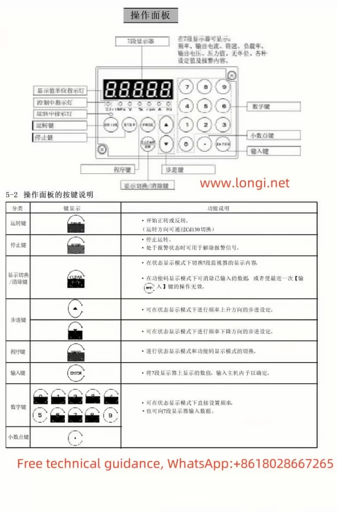
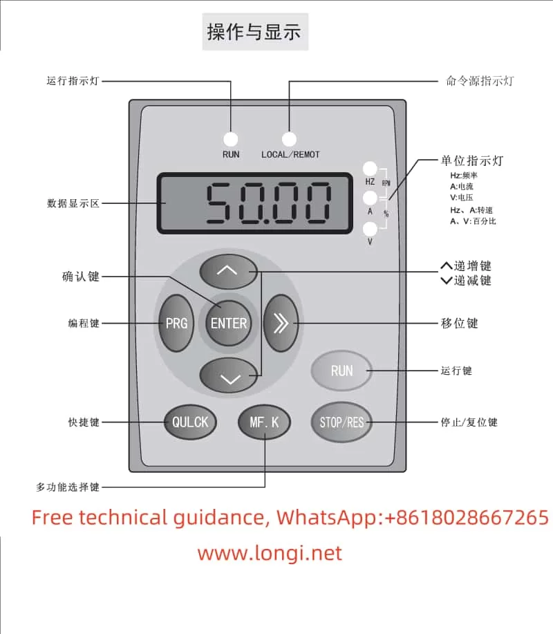
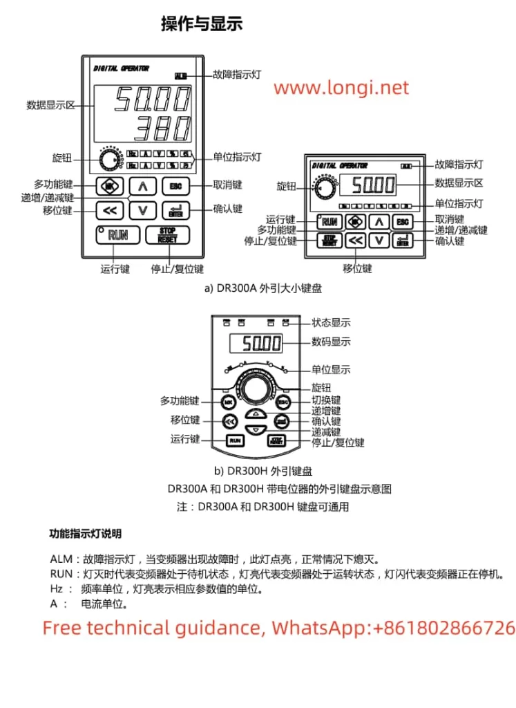
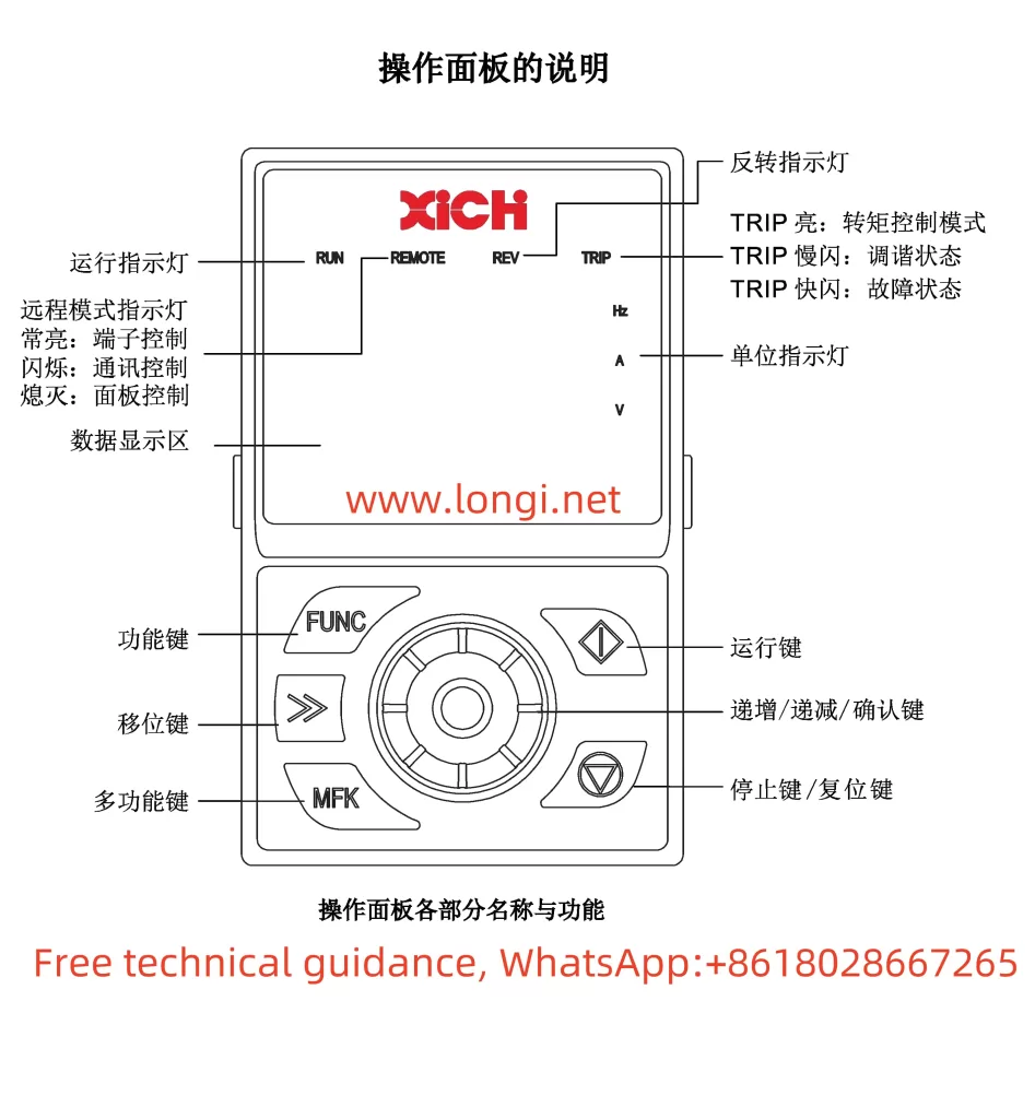
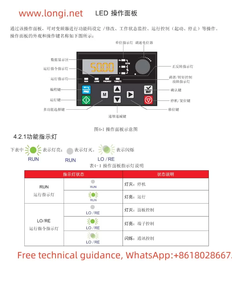
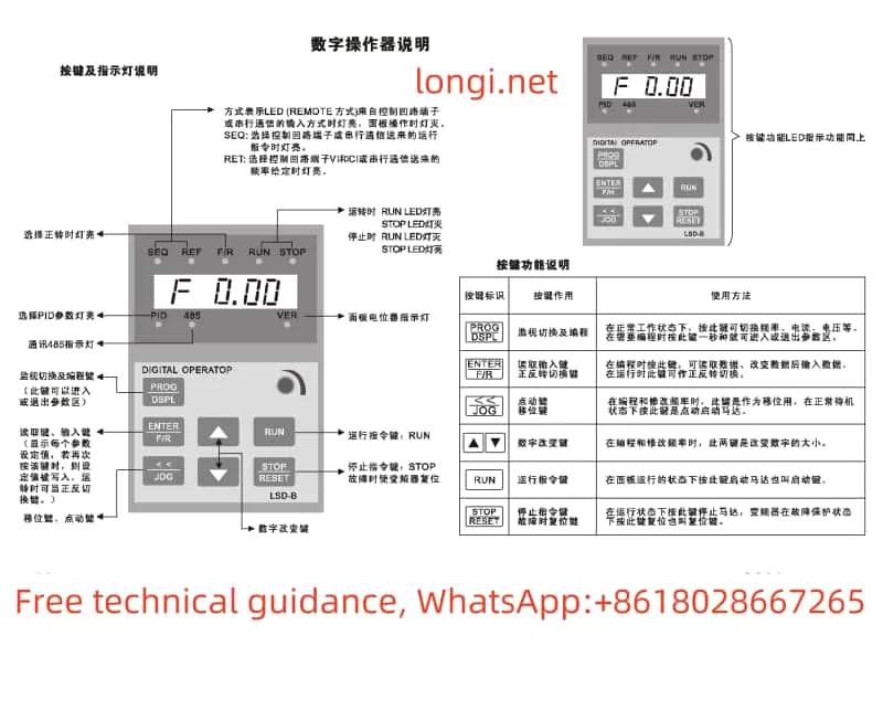
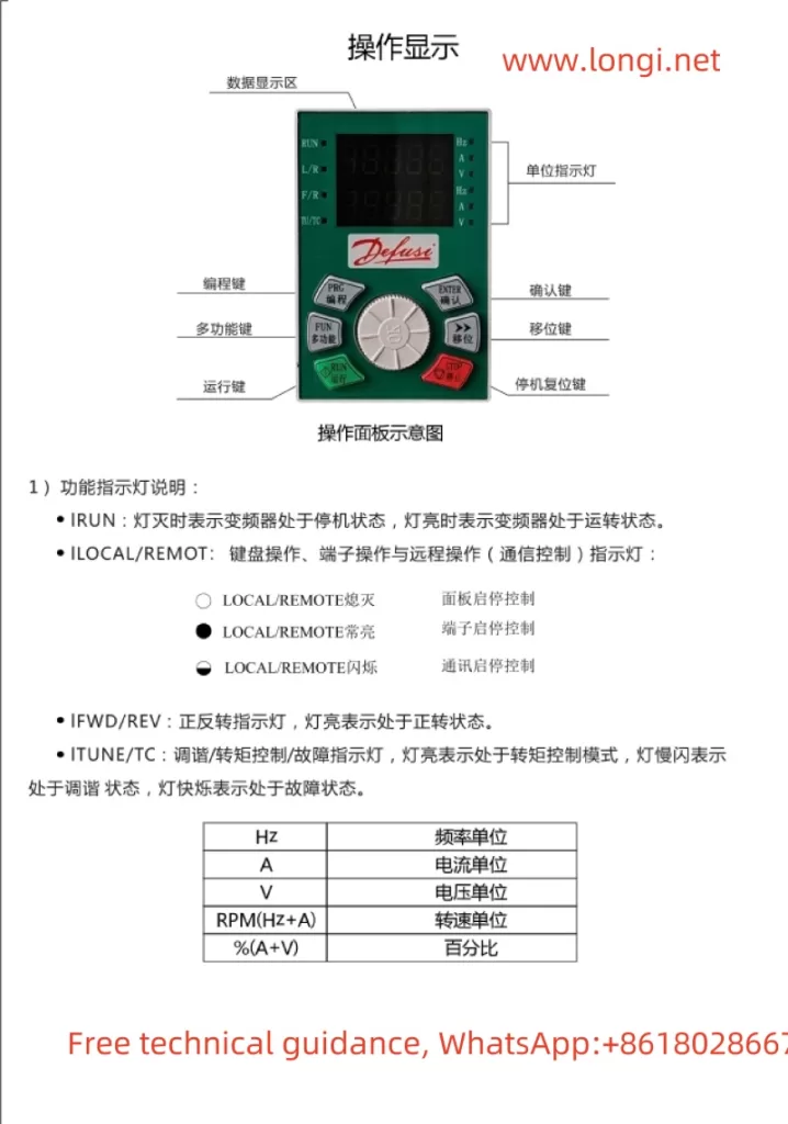
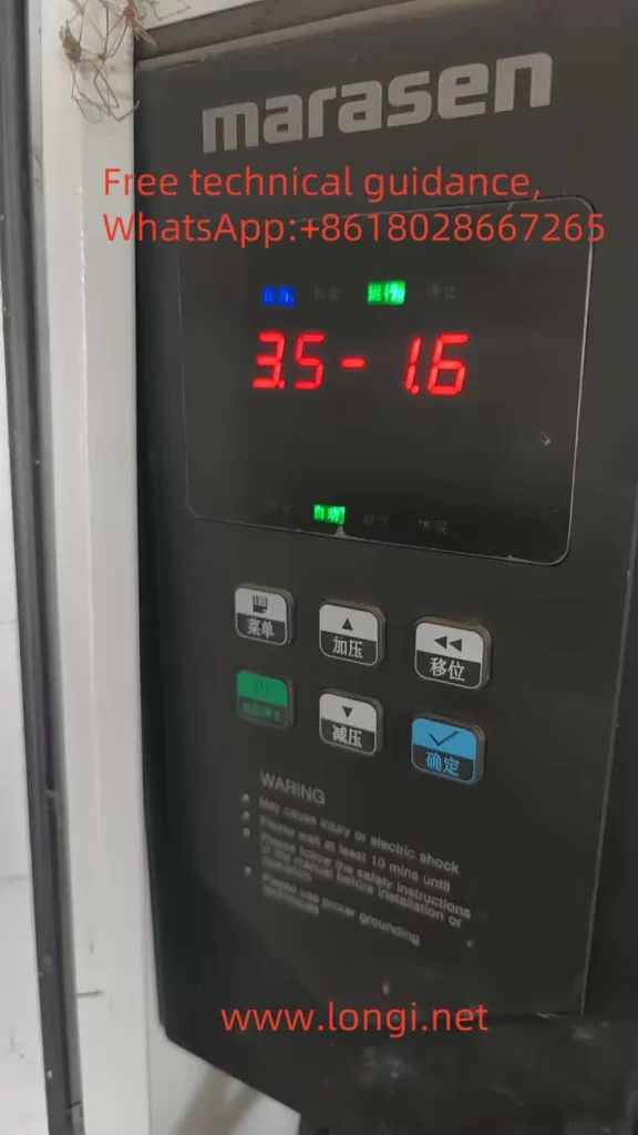
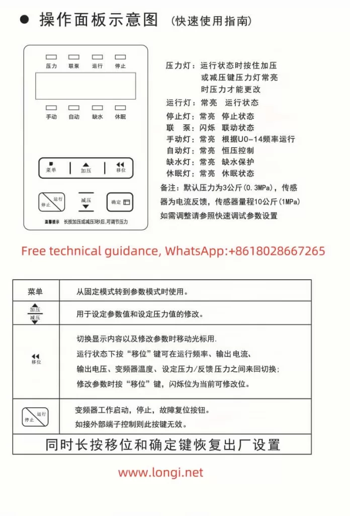
1. Operation Panel Features
The M740 drive panel includes:
- LED Display: Shows real-time operating status, current, voltage, and fault codes.
- Key Functions:
- Start/Stop Button: Controls the operation of the device.
- Shift (▲) and Decrease (▼) Buttons: Used for parameter adjustments.
- Confirm Button: Confirms settings or switches display content.
2. Key Parameters and Codes
The following table provides explanations and configuration methods for key parameter codes:
Pressure Holding Detection Interval (P1.02)
- Function: Sets the time interval for pressure detection to prevent pressure fluctuations from triggering alarms.
- Range: 5-120 seconds (recommended: 30 seconds).
- Default Value: 30 seconds.
Sleep Frequency (P3.01)
- Function: When the drive output frequency is below the set value for a period, the device enters sleep mode.
- Range: 0-50 Hz (recommended: 10 Hz).
- Default Value: 10 Hz.
Water Shortage Detection Mode (P4.01)
- Function: Sets the logic for detecting water shortage.
- Options:
- 0: Disable water shortage detection.
- 1: Pressure mode.
- 2: Current mode.
- Default Value: 1 (Pressure Mode).
Water Shortage Detection Pressure (P4.02)
- Function: Sets the pressure threshold for water shortage detection in pressure mode.
- Range: 0-1.0 MPa (adjust based on site needs).
- Default Value: 0.2 MPa.
Water Shortage Detection Frequency (P4.03)
- Function: Output frequency during water shortage detection.
- Range: 0-50 Hz.
- Default Value: 30 Hz.
Water Shortage Detection Delay (P4.04)
- Function: Sets the delay time to avoid false alarms.
- Range: 1-60 seconds.
- Default Value: 5 seconds.
Water Shortage Detection Current (P4.05)
- Function: Sets the current threshold for water shortage detection in current mode.
- Range: 0-50 A.
- Default Value: 5 A.
2. Protective Features and Settings
1. Anti-Freeze Function (P5.01)
- Function: Prevents pipes from freezing during winter to ensure safe operation in low temperatures.
- Settings:
- Configure the anti-freeze start temperature (recommended: 5°C).
- Ensure the external temperature sensor is properly installed.
2. High/Low-Pressure Alarms (P6.01, P6.02)
- High-Pressure Alarm (P6.01):
- Function: Prevents damage caused by overpressure.
- Range: 0-1.0 MPa (recommended: 0.9 MPa).
- Default Value: 0.9 MPa.
- Low-Pressure Alarm (P6.02):
- Function: Alerts the system when water pressure is insufficient.
- Range: 0-1.0 MPa (recommended: 0.1 MPa).
- Default Value: 0.1 MPa.
3. Feedback Signal Disconnection Protection (P7.01)
- Function: Detects signal integrity to prevent malfunction due to sensor or wiring issues.
- Settings:
- Enable feedback disconnection protection and configure the alarm logic.
4. Sleep Mode (P3.02)
- Function: Puts the system into sleep mode under no-load or low-load conditions to save energy.
- Settings:
- Sleep Delay: Set the time to enter sleep mode (recommended: 10 minutes).
- Wake-Up Mode: Triggered by pressure or flow signals.
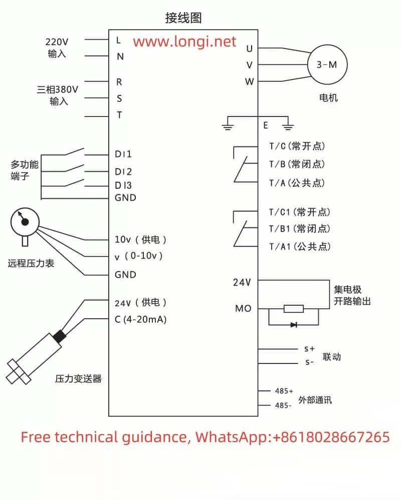
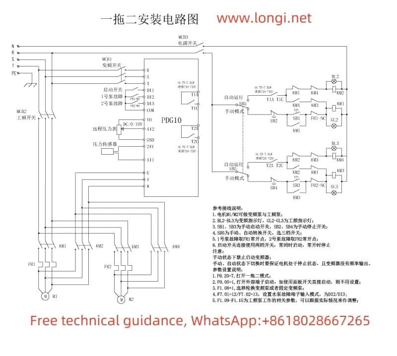
3. Multi-Pump Networking and Parameter Configuration
The M740 supports a multi-pump networking mode, enabling intelligent switching and cooperative operation.
Usage
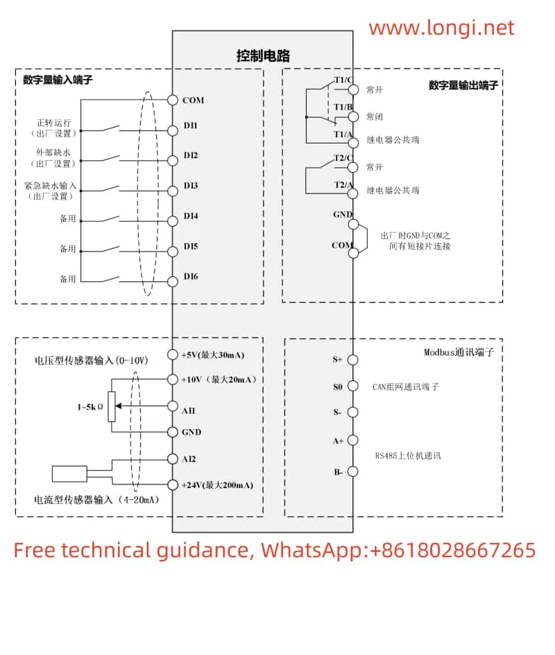
- Communication Configuration: Connect pumps via the RS485 bus and ensure proper communication.
- Master-Slave Pump Switching:
- Set priority levels for master and slave pumps.
- Automatically switch based on cumulative runtime.
Key Parameter Configuration
- Networking Mode (P8.01):
- Set to “1” (Multi-pump Networking Mode).
- Switching Time (P8.02):
- Set to 4-8 hours (adjust as needed).
- Load Balancing (P8.03):
- Enable load balancing to extend device lifespan.
4. Fault Codes and Troubleshooting
Below are common fault codes, their meanings, and suggested solutions:
| Fault Code | Meaning | Solution |
|---|---|---|
| E01 | Motor Overload | Check load conditions and reduce power. |
| E02 | Input Voltage Too Low | Verify that the power supply voltage is stable. |
| E03 | Output Short Circuit | Inspect cables for short circuits or grounding issues. |
| E04 | Heat Sink Overheating | Clean the fan and remove dust from the heat sink. |
| E05 | Feedback Signal Lost | Inspect sensors and communication wiring. |
For other fault codes not listed, refer to the manual’s appendix section.
With this guide, you can quickly start using the M740 drive and gain expertise in its operations. For further assistance, please consult the complete user manual or contact technical support.