Posted on Leave a comment

Application Solution of Holip HLP-A100 Inverter in Napping Machine

Introduction

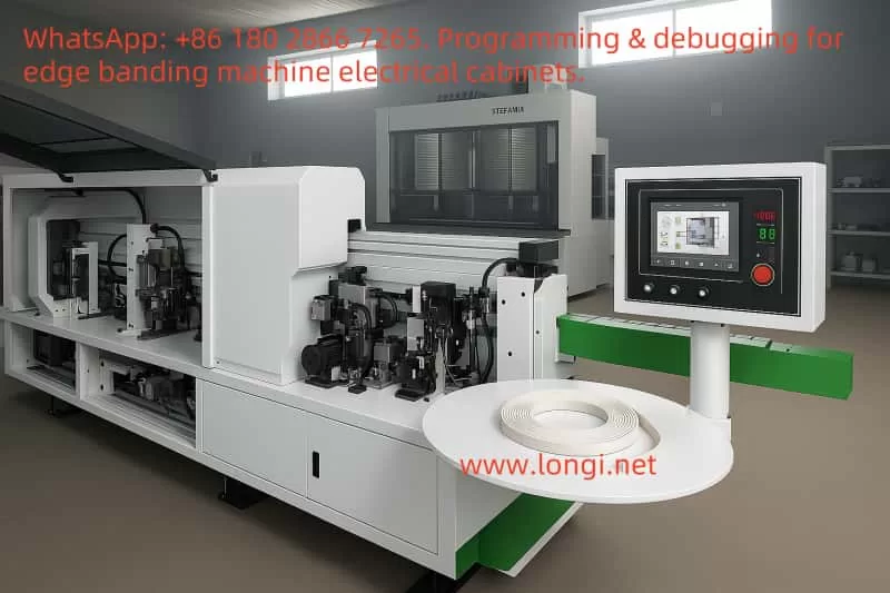
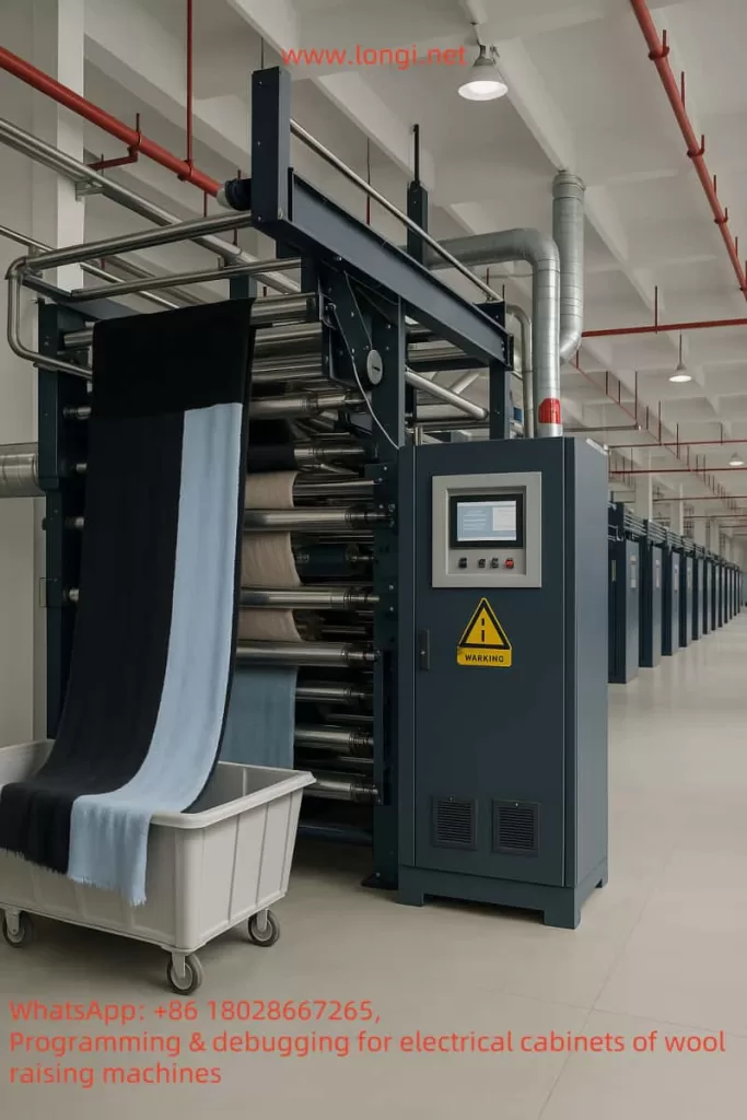
In the production process of textile factories, the napping machine (also known as the wire-drawing machine or yarn-extracting machine), as key equipment, undertakes the important tasks of stretching and homogenizing fibers. It is widely used in processes such as carding and yarn extraction. The Holip HLP-A100 inverter, as a general-purpose vector inverter, with its high reliability, wide range of applications, and rich control functions, can achieve precise control of the napping machine motor. This solution will comprehensively elaborate on the specific application of the Holip HLP-A100 inverter in the napping machine, covering the application positions, wiring methods, parameter settings, control logic, and providing descriptions of the electrical wiring diagram and control schematic. Additionally, equipment such as PLCs, touch screens, or industrial computers can be introduced according to requirements to achieve more advanced control functions.

Textile factory's raising machine

I. Equipment Situation of the Napping Machine and Motor Function Analysis

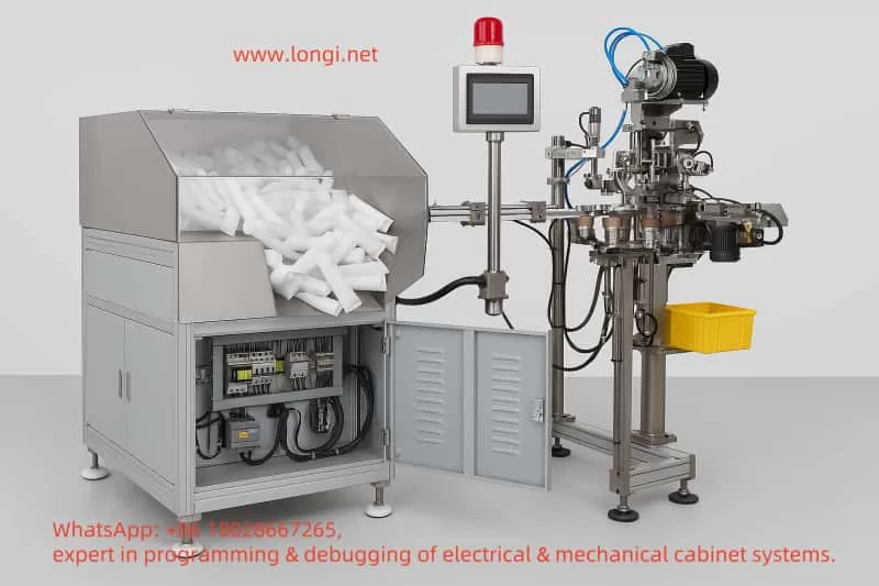
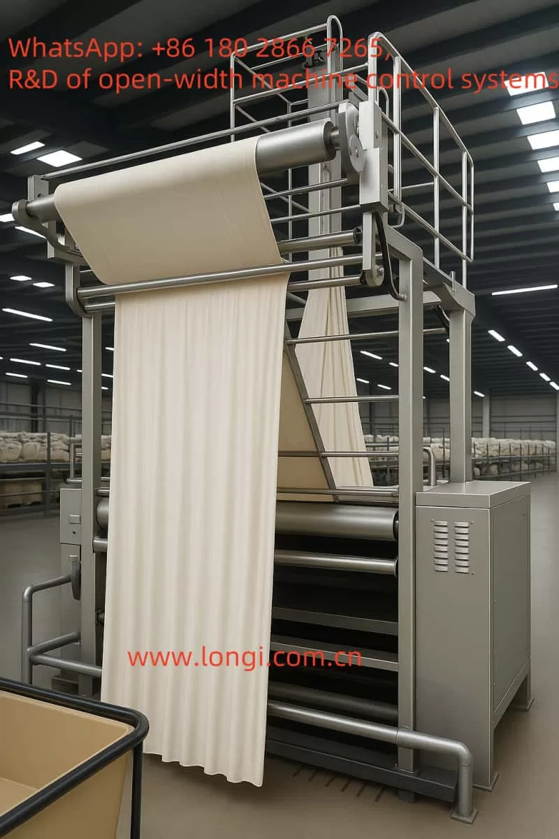
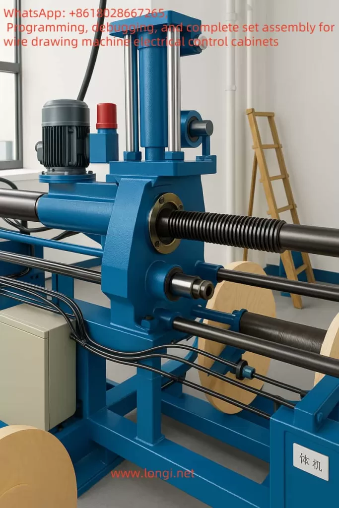
The napping machine mainly stretches and homogenizes fibers through a series of rollers (or rolls). These rollers are usually driven by motors, and some roller groups may require independent motors to achieve precise speed control and ensure a constant drawing ratio (yarn-extracting ratio) of fibers between different rollers. The napping machine mainly includes the following key components and motor functions:

  • Main Stretching Roller Motor: Assumes the main stretching function and requires variable speed control to adapt to different fiber types and production requirements.
  • Auxiliary Roller Motor: Used for auxiliary stretching and fiber conveying, which may run synchronously with the main motor at a fixed speed ratio.
  • Conveying Motor: Responsible for conveying fibers from upstream equipment (such as carding machines) to the napping machine and conveying the processed fibers to downstream equipment (such as spinning machines).
  • Tension Control Motor: Some high-end napping machines are equipped with a dedicated tension control motor to maintain fiber tension and ensure production quality.

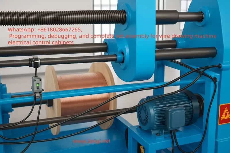
The motors of the napping machine are usually three-phase asynchronous motors with a power range of 1.5kW – 15kW, depending on the machine size and production capacity. This solution is based on the design of a main stretching roller motor with a power of 4kW.

II. Key Features and Specifications of the Holip HLP-A100 Inverter

The Holip HLP-A100 inverter, as a general-purpose vector inverter, is suitable for various motor control needs in the industrial field. Below are its key features and specifications (based on the official manual):

CategoryDetails
Power Range0.75kW – 220kW (models such as HLP-A100001143 to HLP-A100022043)
Voltage RangeThree-phase 380 – 440V/440 – 480V, 50/60Hz
Control ModesSpeed open loop, process closed loop, torque open loop
Digital Inputs/Outputs4 digital inputs (DI1 – DI4), 2 digital outputs (DO1 – DO2), 2 relay outputs (KA – KB, FA – FB – FC)
Analog Inputs/OutputsVI (0 – 10V/4 – 20mA), AI (0 – 10V/4 – 20mA), AO (0 – 20mA/4 – 20mA)
Pulse Inputs/OutputsPulse input (0.001 – 100.0KHz), pulse output (0.001 – 5.0KHz)
Communication ProtocolModbus RTU (address range 1 – 247, baud rate 2400 – 38400)
Special FunctionsSwing function, cascade control, winding control, mechanical braking, multi-speed control, etc.
Environmental AdaptabilityMaximum altitude 1000m (output power or temperature must be reduced when exceeding this limit)

This solution selects a model suitable for a 4kW motor from the HLP-A100 series, such as HLP-A100004043 (the specific model needs to be confirmed according to the manual).

III. Inverter Application Solution Design

3.1 Application Position

The Holip HLP-A100 inverter is mainly applied to the main stretching roller motor of the napping machine to achieve variable speed control of the main stretching roller. If the napping machine has multiple roller groups, multiple HLP-A100 inverters can be used, and cascade control can be implemented to achieve synchronous operation between different rollers and ensure a constant drawing ratio.
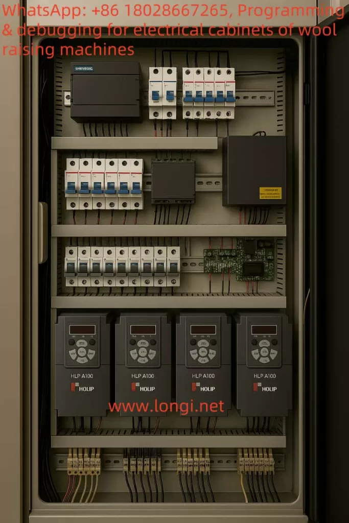
3.2 Wiring Method
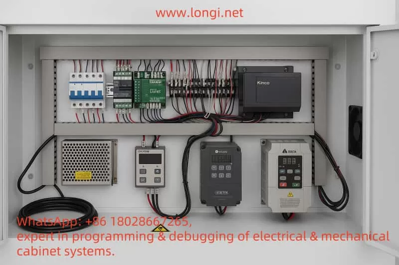
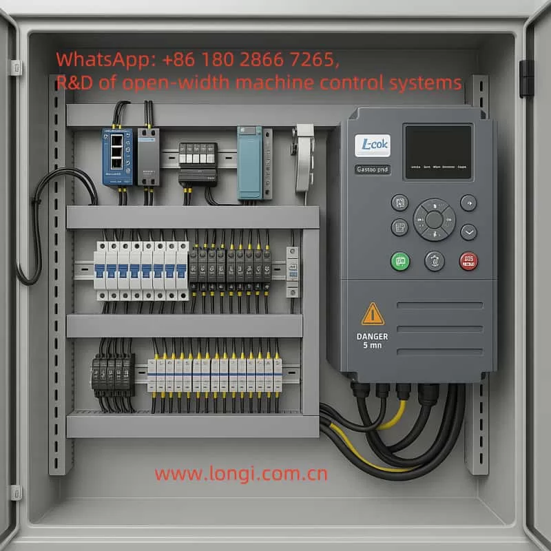
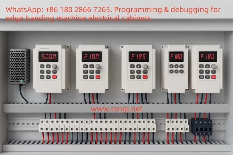
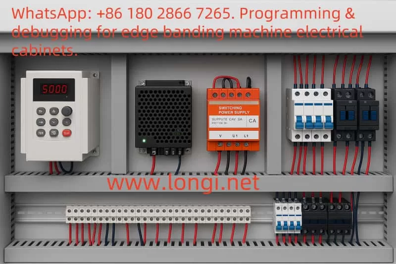
3.2.1 Main Circuit Wiring
  • Main Circuit Terminals:
    • R, S, T: Connect to the three-phase AC power supply (380V/50Hz).
    • U, V, W: Connect to the motor output terminals.
    • PE: Grounding terminal, which must be connected to a reliable ground.
  • Brake Circuit (if required):
    • +UDC, -UDC: Connect to the brake resistor (the resistance value is selected according to the manual, usually 0.15 – 0.4Ω).
3.2.2 Control Circuit Wiring
  • Digital Inputs (DI):
    • DI1: Forward Run.
    • DI2: Stop.
    • DI3: Reverse Run (if required).
    • DI4: Other auxiliary functions (such as emergency stop).
  • Analog Inputs (AI):
    • AI1: Speed reference signal (e.g., provided by an external potentiometer or PLC).
  • Relay Outputs (Relay):
    • KA – KB: Fault alarm output.
    • FA – FB – FC: Running status indication.
  • Communication Interface (RS485):
    • RS+, RS-: Connect to the communication port of the PLC or touch screen.
3.2.3 Wiring Diagram Description

[Three-phase Power Supply] — R, S, T — [Holip HLP-A100 Inverter] — U, V, W — [Main Stretching Roller Motor]
[Ground] — PE — [Holip HLP-A100 Inverter]
[External Control Signal] — DI1(DI2/DI3/DI4) — [Holip HLP-A100 Inverter]
[Speed Reference Signal] — AI1 — [Holip HLP-A100 Inverter]
[Fault Alarm] — KA – KB — [Alarm Light or PLC]
[Running Status] — FA – FB – FC — [Indicator Light or PLC]
[Communication] — RS+, RS- — [PLC/Touch Screen]

3.3 Parameter Settings

Parameter settings are crucial for ensuring the normal operation of the inverter. Below are the typical parameter settings for the main stretching roller motor of the napping machine (based on the HLP-A100 manual):

3.3.1 Basic Parameters
  • C01. Configuration Parameters
    • C01.00 Configuration Mode: Set to “Speed Open Loop”.
    • C01.20 Motor Rated Power: Set to 4.0kW.
    • C01.21 Motor Rated Voltage: Set to 380V.
    • C01.22 Motor Rated Current: Set according to the manual or motor nameplate (e.g., 7.8A).
    • C01.23 Motor Rated Frequency: Set to 50Hz.
    • C01.24 Motor Slip: Set according to the motor parameters (usually 1% – 5%).
3.3.2 Reference and Ramp Parameters
  • C03. Reference/Ramp Parameters
    • C03.03 Maximum Reference: Set to 50.0Hz (or adjust according to actual requirements).
    • C03.04 Minimum Reference: Set to 0.5Hz (to avoid crawling at low speeds).
    • C03.05 Acceleration Time 1: Set to 5.0 seconds (adjust according to production requirements).
    • C03.06 Deceleration Time 1: Set to 5.0 seconds (adjust according to production requirements).
3.3.3 Digital Input/Output Parameters
  • C05. Digital Input/Output Parameters
    • C05.00 DI1 Function: Set to “Forward Run”.
    • C05.01 DI2 Function: Set to “Stop”.
    • C05.02 DI3 Function: Set to “Reverse Run” (if required).
    • C05.10 DO1 Function: Set to “Running Status”.
3.3.4 Analog Input/Output Parameters
  • C06. Analog Input/Output Parameters
    • C06.99 AI1 Function: Set to “Frequency Command”.
3.3.5 Cascade Control Parameters (if synchronous control is required)
  • C25. App. Functions Cascade Parameters
    • If multiple motors need to be synchronized, the main inverter can be set as the master, and the auxiliary inverters can be set as slaves, with the frequency ratio set.
3.4 Advanced Control Solution: Introducing PLC and Touch Screen

To achieve more advanced control and a user interface, a PLC and touch screen can be introduced. Below is the recommended solution:

3.4.1 PLC Selection

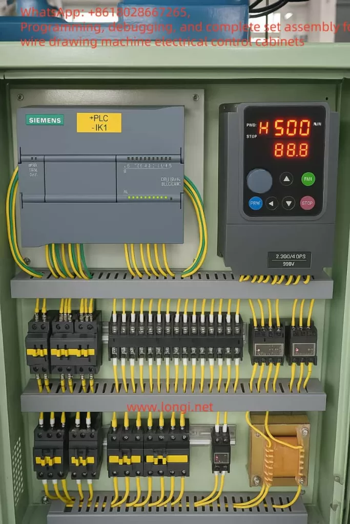
Select a PLC that supports the Modbus RTU protocol, such as the Siemens S7-200 series or Schneider Modicon series. The PLC is responsible for handling logic control, such as start, stop, speed setting, and fault handling.

3.4.2 Touch Screen Selection

Select a touch screen that supports Modbus RTU, such as the Weintek MT8071i series. The touch screen is used for the user interface, providing start/stop buttons, speed setting sliders, status displays, etc.

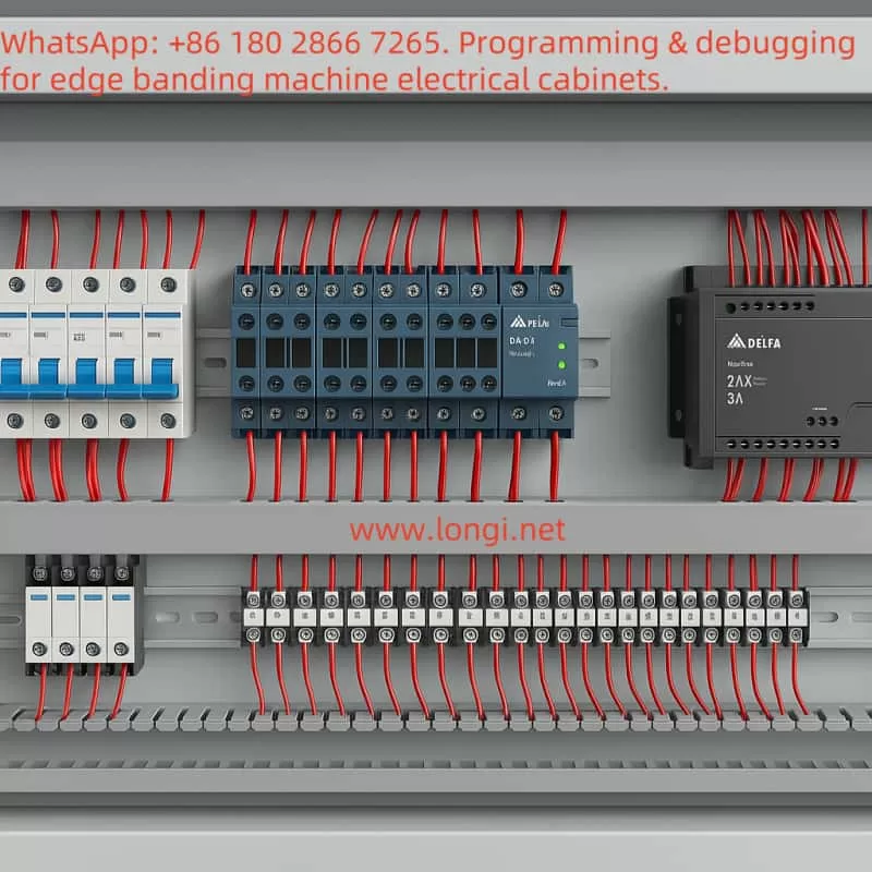
3.4.3 PLC and Touch Screen Wiring
  • The PLC is connected to the inverter via RS485 communication.
  • The touch screen is connected to the PLC’s communication port or directly to the inverter (if the touch screen supports direct control).
3.4.4 PLC Program Design
  • Use the PLC’s Modbus function blocks to read the inverter’s status (such as running status, output frequency).
  • Use the PLC’s Modbus function blocks to write control commands to the inverter (such as start, stop, frequency setting).
  • Logic can be added to the PLC program, such as:
    • When the start button is pressed, send the start command after checking safety conditions.
    • When the speed setting changes, update the inverter’s frequency command.
3.4.5 Touch Screen Design
  • Main Screen: Display the current speed, running status, and fault information.
  • Control Buttons: Start, stop, emergency stop.
  • Parameter Setting Page: Allow adjustment of acceleration/deceleration time, maximum/minimum frequency, etc.
Control cabinet for raising machine

IV. Control Schematic Description

Below is a description of the overall control schematic of the system:

[Three-phase Power Supply] — [Holip HLP-A100 Inverter] — [Main Stretching Roller Motor]
[External Control Signal] — [Holip HLP-A100 Inverter] — [PLC]
[PLC] — [Touch Screen]
[PLC] — [Other Auxiliary Devices (such as alarm lights, indicator lights)]

V. Summary and Key Notes

The application of the Holip HLP-A100 inverter in the napping machine can significantly improve production efficiency and product quality. Through precise speed control and synchronization functions, it ensures the uniform stretching of fibers. Below are the key notes:

  • Model Selection: Select the appropriate inverter model according to the power of the napping machine motor.
  • Wiring: Ensure correct connection of the main circuit and control circuit, paying attention to grounding and shielding.
  • Parameter Settings: Adjust parameters such as acceleration/deceleration time and maximum/minimum frequency according to actual production requirements.
  • Safety Protection: Ensure that the emergency stop function works normally and comply with relevant safety standards.
  • Advanced Control: Achieve more flexible control and monitoring through PLC and touch screen.

Through the implementation of this solution, the efficient operation of the napping machine can be achieved, providing more reliable production assurance for textile factories.


Posted on Leave a comment

Application Scheme of Kinco CV20 Inverter in PE Pipe Packaging and Pipe Arranging Machine

I. Introduction

This document aims to design a detailed application scheme based on the Kinco CV20 inverter for the PE pipe packaging and pipe arranging machine (winding machine). The scheme covers motor function analysis, inverter selection, wiring methods, parameter settings, and control system integration. The pipe arranging machine uses a winding mechanism to evenly wrap PE pipes onto a reel, requiring precise control of winding speed and tension. The CV20 inverter, with its variable frequency speed regulation and communication capabilities, can meet the requirements of multi-motor coordinated control.

II. Motor Function Analysis for the Pipe Arranging Machine

Main Winding Motor

  • Function: Drives the winding mechanism to control the winding speed and tension of the PE pipe.
  • Parameters: Three-phase asynchronous motor, 380V/2.2kW.

Lateral Movement Motor

  • Function: Drives the conduit device to move horizontally, ensuring even distribution of the pipes.
  • Parameters: Three-phase motor (or single-phase), 380V/0.75kW.

Auxiliary Motor

  • Function: Such as driving a conveyor belt, with low power and no need for inverter control.
  • Application Positioning: The CV20 inverter is mainly used for speed regulation and synchronous control of the main winding motor and lateral movement motor.
Tube Organizing Machine

III. CV20 Inverter Selection

Motor TypeModelApplicable Scenario
Main Winding Motor (2.2kW)CV20-4T-0022GThree-phase 380V input/output
Lateral Movement Motor (0.75kW)CV20-4T-0007GThree-phase 380V input/output
Lateral Movement Motor (Single-phase)CV20-2S-0007GSingle-phase 220V input/output (optional)

Key Features:

  • Output Frequency: 0-300Hz, supports V/F control and automatic torque boost.
  • Communication Interface: Built-in Modbus RS485, compatible with PLC integration.
  • Environmental Adaptability: Temperature -10℃~50℃, humidity 5%~95%RH.

IV. Wiring Methods

1. Main Circuit Wiring

  • Power Input: Three-phase 380V AC → Circuit Breaker → Inverter R/L1, S/L2, T/L3 (PE grounded).
  • Motor Output: Inverter U/T1, V/T2, W/T3 → Motor U, V, W.

2. Control Circuit Wiring

  • Control Methods:
    • Keyboard Control: Directly set frequency and start/stop.
    • Terminal Control:
      • X1: Start/Stop
      • X2: Forward/Reverse (Lateral Movement)
      • X3: Emergency Stop
      • AI1: Analog Frequency Input
    • Communication Control: RS485 interface (+5V, 485+, 485-, GND) connected to PLC/HMI.
  • Wiring Example:复制代码Main Power (R,S,T,PE) ----> [Circuit Breaker] ----> [CV20-4T-0022G] (R/L1,S/L2,T/L3,PE) ----> [Main Winding Motor] (U,V,W) | |----> [CV20-4T-0007G] (R/L1,S/L2,T/L3,PE) ----> [Lateral Movement Motor] (U,V,W)Control Circuit:External Start Button ----> X1 (CV20-4T-0022G)Analog Signal Source ----> AI1 (CV20-4T-0022G)

V. Parameter Settings

1. Main Winding Motor (CV20-4T-0022G)

ParameterSetting ValueDescription
P1380VRated Voltage
P710sAcceleration Time
P10Linear V/FConstant Torque Load Mode
P41-P45Enable PIDTension Control (requires sensor)

2. Lateral Movement Motor (CV20-4T-0007G)

ParameterSetting ValueDescription
P35HzMaximum Frequency (low-speed movement)
P20Triangle Wave ModeAchieve reciprocating motion
P21Set according to winding widthTriangle wave period

VI. PLC and HMI Selection

  • PLC: Recommend Siemens S7-200 (e.g., S7-224) or Omron CP1E, supporting Modbus communication.
  • HMI: Recommend Siemens KTP400 or Omron NB5W, for parameter setting and status monitoring.
  • Communication Configuration:
    • Inverter P51: Modbus-RTU protocol
    • Baud Rate P52: 9600bps
  • Control Architecture:复制代码PLC ----> [RS485] ----> CV20-4T-0022G ----> Main Winding Motor | |----> [RS485] ----> CV20-4T-0007G ----> Lateral Movement Motor | |----> HMI (display status, set parameters)

VII. Function Realization

Main Winding Motor:

  • Speed Control: Achieve multi-level winding speeds through frequency adjustment.
  • Tension Control: PID closed-loop regulation (requires tension sensor).

Lateral Movement Motor:

  • Reciprocating Motion: Automatic direction switching using triangle wave frequency mode.
  • Synchronous Control: PLC reads the main motor frequency and dynamically adjusts the lateral speed.

VIII. Safety and Protection Measures

  • Grounding Protection: PE terminal reliably grounded, grounding wire ≥3.5mm².
  • Overcurrent Protection: Main circuit equipped with circuit breakers/fuses.
  • Emergency Stop Function: X3 terminal connected to emergency stop button.
  • Voltage Protection: Inverter built-in overvoltage/undervoltage alarm.
Control Cabinet for Tube

IX. Conclusion

The Kinco CV20 inverter can efficiently control the main winding and lateral movement motors of the PE pipe arranging machine through flexible wiring methods, parameter configuration, and communication functions. It is recommended to build an automated system in combination with PLC and HMI, with specific model selection referring to Siemens or Omron products. Users need to further optimize settings based on actual equipment parameters and follow the manufacturer’s safety specifications.

Note: This scheme is a general design, and parameters and wiring may need to be adjusted in actual applications based on equipment manuals and site conditions.

Posted on Leave a comment

Application Scheme of LC400E Inverter in the Unwinding and Slitting Machine

I. Scheme Overview

This scheme aims to apply the Lianchuang High-Tech LC400E inverter to the unwinding and slitting machine. By precisely controlling the motor speed and torque, it achieves automation and efficient operation of core functions such as unwinding, cutting, and rewinding. The scheme covers motor function analysis, wiring methods, parameter settings, function realization, and auxiliary equipment selection to ensure the efficiency and stability of the unwinding and slitting machine’s production.

II. Analysis of the Unwinding and Slitting Machine Structure and Motor Configuration

Equipment Functions
The unwinding and slitting machine is used to cut wide rolls of materials into multiple narrow rolls. Its core functions include unwinding, cutting, and rewinding.

Motor Configuration

  • Unwinding Motor: Controls the unwinding speed of the parent roll and requires constant tension to prevent material slack or breakage.
  • Rewinding Motor: Controls the winding of narrow materials and requires tension adjustment according to the roll diameter (trapezoidal tension).
  • Cutting Motor: Drives the cutting components and requires precise speed control.

Control Requirements
Tension control is the core requirement. It needs to achieve constant tension during unwinding and trapezoidal tension during rewinding through motor torque control.

scutcher

III. Key Features of the LC400E Inverter

  • High-Performance Vector Control: Supports precise speed and torque control to meet tension synchronization requirements.
  • Multi-Mode Control: Terminal control, analog input, and multi-speed settings to adapt to different working conditions.
  • Safety Protection: Functions such as overvoltage, overcurrent, and motor protection ensure equipment safety.
  • Communication Capabilities: Supports Modbus communication (RS232/RS485) for easy integration with PLC/HMI.
  • Adjustable Parameters: Acceleration/deceleration time, PID control, and other parameters can be flexibly adjusted.
  • Specifications: Power range from 0.75 kW to 500 kW, with output current reaching 63 A for models like G022/T4, suitable for the motor requirements of the unwinding and slitting machine.

IV. Application Positions of the LC400E in the Unwinding and Slitting Machine

  • Unwinding Motor: Torque control mode to maintain constant tension.
  • Rewinding Motor: Speed/torque control mode to support trapezoidal tension adjustment.
  • Cutting Motor: Speed control mode to ensure cutting accuracy.
    Application Suggestions: Configure multiple inverters according to the number of motors, such as one for the unwinding motor and one for the rewinding motor.

V. Wiring Methods

Main Circuit Wiring

  • Connect the input terminals (R, S, T) to the three-phase power supply and the output terminals (U, V, W) to the motor. Connect the PE terminal to the ground.
  • Refer to the LC400E manual for wire size specifications (e.g., for a 22 kW model, the input is 100 A, and the output is 63 A).

Control Circuit Wiring

  • Start/Stop Control: DI1 (forward), DI2 (reverse), DI3 (stop).
  • Speed Control: AI1 connects to the speed reference signal (e.g., potentiometer or PLC output).
  • Tension Control: AI2 connects to the tension sensor output (if available).
  • Fault Signal: DO1 connects to the alarm system.
  • Communication: RS485 connects to the PLC/HMI.

Electrical Wiring Diagram (Text Description)

  • [Main Circuit]
    Power (three-phase) — R, S, T — LC400E — U, V, W — Motor
    PE — Ground
  • [Control Circuit]
    Start/Stop Buttons — DI1/DI2/DI3
    Speed Reference — AI1
    Tension Feedback — AI2
    Fault Output — DO1
    Communication — RS485 — PLC/HMI

VI. Parameter Settings

Basic Parameters

  • P0-02: Set the operation command source to 1 (terminal control).
  • P0-03: Set the frequency command source to 2 (AI1).
  • P0-17/P0-18: Set the acceleration/deceleration time to 1.5 seconds.
  • P6-10: Set the stop mode to 0 (deceleration stop).

Tension Control Parameters

  • Unwinding Motor: Enable torque control (P3-00) and set the torque command source to AI2 (if a sensor is available).
  • Rewinding Motor: Enable trapezoidal tension control (P7-00).

Multi-Speed Settings

  • Set P0-03 to 6 (multi-speed command). Use DI4/DI5 to select the speed segment, and set the speed values in PC-00~PC-15.

Parameter Setting Table

Parameter NumberFunctionSetting ValueDescription
P0-02Operation Command Source1Terminal Control
P0-03Frequency Command Source2/6AI1 or Multi-Speed
P3-00Torque Control ModeEnabledConstant Tension During Unwinding
P7-00Trapezoidal Tension ControlEnabledTension Adjustment During Rewinding
Open range electromechanical control cabinet

VII. Functions Realized

  • Precise Speed Control: Set the speed through AI1 and support multi-speed switching.
  • Tension Control: Maintain constant tension during unwinding and trapezoidal tension during rewinding to prevent material breakage or slack.
  • Synchronization Control: The PLC coordinates the operation of multiple motors to ensure uniform tension.
  • Fault Protection: DO1 outputs fault signals, and P6 group parameters set protection functions.
  • Communication Integration: Modbus protocol enables remote monitoring and parameter adjustment.

VIII. PLC, Touch Screen, and Industrial Computer Selection

PLC Selection

  • Recommended models: Siemens S7-1200 (high performance) or Mitsubishi FX series (cost-effective).

Touch Screen Selection

  • Recommended models: Siemens KTP600 (easy to operate) or Mitsubishi GOT series (multi-language support).

Application Description

  • PLC Functions: Read HMI inputs, send control commands, monitor status, and coordinate multiple motors.
  • HMI Functions: Provide an operation interface, display status information, and support data logging.

Communication Connection

  • Connect the PLC to the LC400E via RS485 with a baud rate of 9600 and no parity.

Control Diagram (Text Description)

  • HMI — Ethernet/Serial — PLC
    PLC — RS485 — LC400E (Unwinding/Rewinding/Other Motors)
    PLC Program: Read HMI Inputs → Send Control Commands → Read Status → Update HMI Display

IX. Precautions and Safety Considerations

  • Safety Protection: Install an emergency stop button and set inverter protection parameters.
  • Tension Control: Prioritize the installation of tension sensors to ensure control accuracy.
  • Multi-Motor Synchronization: Coordinate through the PLC to avoid uneven tension.
  • Environmental Requirements: Install the inverter in a well-ventilated and dry environment, away from dust and moisture.

X. Summary

This scheme achieves high-precision speed and tension control through the application of the LC400E inverter in the unwinding and slitting machine, combined with PLC and HMI for automated operation. Key measures include:

  • Adopting constant tension and trapezoidal tension control for the unwinding and rewinding motors, respectively.
  • Using standard wiring methods and key parameter settings to ensure system stability.
  • Selecting Siemens/Mitsubishi equipment to achieve efficient automated control.
    This scheme can significantly improve the production efficiency of the unwinding and slitting machine, reduce operation difficulty and fault risks, and is suitable for the roll material processing industry.
Posted on Leave a comment

Application Scheme of Mobeck MT110 Inverter in a Rotary Cutting Machine

Introduction

The rotary cutting machine is an essential piece of equipment in the woodworking industry, primarily used to peel logs into thin veneer sheets, which are widely applied in the production of plywood, furniture, and decorative materials. To achieve efficient and precise processing, the rotary cutting machine relies on the coordinated operation of multiple motors, including the main spindle motor for log rotation, the cutting blade motor for veneer cutting, the conveyor belt motor for veneer output, and the feed motor for controlling cutting thickness. These motors require precise speed and torque control to ensure processing quality and production efficiency. As a versatile electrical device capable of flexibly controlling motor operation, the inverter plays a critical role in the rotary cutting machine.

This article provides a detailed explanation of how to apply the Mobeck MT110 inverter to various motor control aspects of a rotary cutting machine, covering functional analysis, inverter selection, wiring design, parameter settings, and the integration of PLC and touchscreen systems. Through a well-designed and implemented solution, the rotary cutting machine can achieve efficient, stable, and automated operation, meeting the demands of modern woodworking processes.


Veneer peeling machine

Functional Analysis of the Rotary Cutting Machine

The primary task of a rotary cutting machine is to process logs into veneer sheets, involving log fixation and rotation, cutting by the blade, veneer output, and precise control of cutting thickness. Below is a detailed analysis of the main motor functions in a rotary cutting machine:

1. Main Spindle Motor (Rotation Function)

  • Function: The main spindle motor drives the log to rotate, serving as the core power component of the rotary cutting machine.
  • Characteristics: It requires high power, typically ranging from 5.5 kW to 15 kW (depending on the machine size), and needs stable speed output while allowing dynamic speed adjustments based on processing requirements.
  • Control Requirements: The inverter must support vector control mode to ensure high torque output at low speeds and be capable of receiving external speed reference signals (e.g., from a PLC or potentiometer).

2. Cutting Blade Motor (Cutting Function)

  • Function: This motor drives the cutting blade to peel the rotating log into veneer sheets.
  • Characteristics: The power typically ranges from 3 kW to 7.5 kW, with speed adjustments required based on veneer thickness, and stable torque support during cutting.
  • Control Requirements: The inverter needs fast start/stop capabilities and precise speed control, often requiring synchronization with the main spindle motor.

3. Conveyor Belt Motor (Conveying Function)

  • Function: It ensures the smooth output of cut veneer sheets, maintaining production continuity.
  • Characteristics: The power is relatively low, typically between 0.75 kW and 2.2 kW, with speed needing to match the cutting rhythm.
  • Control Requirements: The inverter should support simple speed regulation and may need to operate in coordination with the cutting blade motor.

4. Feed Motor (Feed Function)

  • Function: It controls the feed speed of the cutting blade or log, directly determining the veneer thickness.
  • Characteristics: The power is low (0.75 kW to 1.5 kW), and it can be either an asynchronous motor or a servo motor, requiring high-precision speed control.
  • Control Requirements: If using an asynchronous motor, the inverter must support high-precision speed regulation and accept external analog signal inputs; if using a servo motor, a dedicated servo drive is required.

5. Other Auxiliary Motors

  • Function: These include motors for clamping devices, chip removal fans, etc., used to assist the processing operation.
  • Characteristics: The power is low (0.37 kW to 1.5 kW), with simple control requirements, typically needing only basic start/stop functions.

From the above analysis, it is clear that the motor control requirements of a rotary cutting machine are diverse. The main spindle and cutting blade motors demand high-performance control, while the conveyor belt and feed motors prioritize speed stability and precision. The Mobeck MT110 inverter, with its flexible control modes and rich functionality, is an ideal choice to meet these requirements.


Application Scheme of Mobeck MT110 Inverter

1. Inverter Application Positions

Based on the functional characteristics of the rotary cutting machine, the Mobeck MT110 inverter can be applied to the following key motor positions:

  • Main Spindle Motor: Use the MT110 inverter for vector control to ensure stable log rotation.
  • Cutting Blade Motor: Use the MT110 inverter for speed control, synchronized with the main spindle motor.
  • Conveyor Belt Motor: Use the MT110 inverter for simple speed regulation.
  • Feed Motor: If an asynchronous motor is used, the MT110 inverter can provide high-precision speed control; if a servo motor is used, a separate servo drive is required.

2. Inverter Selection

Assuming a medium-sized rotary cutting machine with the following motor power configuration:

  • Main Spindle Motor: 7.5 kW
  • Cutting Blade Motor: 5.5 kW
  • Conveyor Belt Motor: 1.5 kW
  • Feed Motor: 1.1 kW (asynchronous motor)

Based on the motor power and load characteristics, the following Mobeck MT110 inverter models are selected:

  • Main Spindle Motor: MT110-7.5kW (rated power 7.5 kW, 380V three-phase)
  • Cutting Blade Motor: MT110-5.5kW (rated power 5.5 kW, 380V three-phase)
  • Conveyor Belt Motor: MT110-1.5kW (rated power 1.5 kW, 380V three-phase)
  • Feed Motor: MT110-1.1kW (rated power 1.1 kW, 380V three-phase)

When selecting the inverter, ensure that its rated capacity is slightly higher than the motor power to provide a margin for potential overload conditions.

3. Wiring Design

The following uses the main spindle motor (7.5 kW) MT110 inverter as an example to detail the wiring method. The wiring for other motors is similar, with adjustments based on power and control requirements.

(1) Main Circuit Wiring

  • Power Input: Connect the three-phase 380V power supply to the inverter’s R, S, and T terminals.
  • Motor Output: Connect the inverter’s U, V, and W terminals to the three-phase input of the main spindle motor.
  • Grounding: Connect the inverter’s grounding terminal and the motor’s grounding terminal to the ground wire to ensure electrical safety.

Main Circuit Wiring Diagram (Text Description):

Power Supply (380V Three-Phase)
  L1 ---- R
  L2 ---- S
  L3 ---- T
         |
         |---- Ground Terminal ---- Ground
         |
  U ---- Motor U Phase
  V ---- Motor V Phase
  W ---- Motor W Phase
         |
         |---- Motor Ground Terminal ---- Ground

(2) Control Circuit Wiring

The control terminals of the MT110 inverter include digital inputs (DI), analog inputs (AI), and relay outputs (RO). Using the main spindle motor control as an example:

  • Start/Stop Control:
  • DI1 (Forward Start): Connect to the PLC output point (e.g., Y0) to control inverter start via the PLC.
  • DI2 (Stop): Connect to the PLC output point (e.g., Y1) to control inverter stop via the PLC.
  • COM: Common terminal, connected to the PLC’s common terminal.
  • Speed Reference:
  • AI1 (Analog Input): Connect to the PLC’s analog output module (0-10V signal) for speed regulation.
  • GND: Analog ground, connected to the PLC’s analog ground.
  • Fault Output:
  • RO1A/RO1B (Relay Output): Connect to the PLC input point (e.g., X0) to detect inverter faults.

Control Circuit Wiring Diagram (Text Description):

PLC Output
  Y0 ---- DI1 (Forward Start)
  Y1 ---- DI2 (Stop)
  COM ---- PLC Common Terminal

PLC Analog Output
  0-10V ---- AI1 (Speed Reference)
  GND ---- GND

Inverter Relay Output
  RO1A ---- X0 (PLC Input, Fault Detection)
  RO1B ---- PLC Common Terminal

4. Parameter Settings

Using the main spindle motor (7.5 kW) MT110 inverter as an example, the key parameter settings are listed below. Assuming the MT110 inverter’s parameter numbering is similar to that of a general-purpose inverter, the settings are as follows:

  • P0.03 (Control Mode): Set to 1 (Vector Control without PG), suitable for the high torque requirements of the main spindle motor.
  • P0.04 (Run Command Source): Set to 1 (Terminal Control), using DI1/DI2 for start/stop control.
  • P0.06 (Frequency Reference Source): Set to 2 (AI1 Analog Input), using the PLC’s 0-10V signal to set the speed.
  • P1.00 (Motor Rated Power): Set to 7.5 (7.5 kW).
  • P1.01 (Motor Rated Voltage): Set to 380 (380V).
  • P1.02 (Motor Rated Frequency): Set to 50 (50 Hz).
  • P1.03 (Motor Rated Speed): Set to 1460 (assuming a 4-pole motor, approximately 1460 rpm at 50 Hz).
  • P2.00 (Acceleration Time): Set to 5 (5 seconds) to avoid startup shock.
  • P2.01 (Deceleration Time): Set to 5 (5 seconds) to ensure smooth stopping.
  • P5.00 (DI1 Function): Set to 1 (Forward Run).
  • P5.01 (DI2 Function): Set to 2 (Stop).
  • P6.00 (Relay Output Function): Set to 1 (Fault Output).

Parameter settings for other motors should be adjusted based on their specific functions:

  • Cutting Blade Motor: Set acceleration/deceleration time to 3 seconds to accommodate fast start/stop requirements.
  • Conveyor Belt Motor: Use V/F control (P0.03=0) to simplify control logic.
  • Feed Motor: Requires high-precision speed control, so adjust the gain and offset parameters of AI1 (e.g., P4 group parameters).

Parameter Settings Example Table:

Parameter No.DescriptionMain Spindle MotorCutting Blade MotorConveyor Belt MotorFeed Motor
P0.03Control Mode1 (Vector)1 (Vector)0 (V/F)1 (Vector)
P0.04Run Command Source1 (Terminal)1 (Terminal)1 (Terminal)1 (Terminal)
P0.06Frequency Reference Source2 (AI1)2 (AI1)2 (AI1)2 (AI1)
P1.00Motor Rated Power (kW)7.55.51.51.1
P2.00Acceleration Time (s)5322
P2.01Deceleration Time (s)5322

5. PLC and Touchscreen Selection and Application

(1) Selection

To achieve automated control of the rotary cutting machine, a PLC and touchscreen are required:

  • PLC: Recommend the Siemens S7-200 SMART series (e.g., CPU 224XP), which supports analog input/output and offers strong scalability.
  • Touchscreen: Recommend the Siemens KTP400 Basic (7-inch), which supports communication with the PLC via Profinet and provides an intuitive operation interface.

(2) PLC Program Design

The PLC is responsible for coordinating the operation of each motor, with the main functions including:

  • Start/Stop Control: Use PLC output points (e.g., Y0, Y1) to control the DI1/DI2 of each inverter, enabling motor start/stop.
  • Speed Regulation: Use the PLC’s analog output module (0-10V) to control the inverter’s AI1, dynamically adjusting each motor’s speed.
  • Synchronization Control: Calculate the speed ratio between the main spindle motor and the cutting blade motor through the program to ensure consistent cutting thickness.
  • Fault Detection: Use the inverter’s relay output (RO1A/RO1B) to send fault signals to the PLC input point (e.g., X0), triggering an alarm.

PLC Control Diagram (Text Description):

PLC
  Y0 ---- Main Spindle Inverter DI1 (Start)
  Y1 ---- Main Spindle Inverter DI2 (Stop)
  AO0 ---- Main Spindle Inverter AI1 (Speed Reference)
  X0 ---- Main Spindle Inverter RO1A (Fault Input)

  Y2 ---- Cutting Blade Inverter DI1 (Start)
  Y3 ---- Cutting Blade Inverter DI2 (Stop)
  AO1 ---- Cutting Blade Inverter AI1 (Speed Reference)
  X1 ---- Cutting Blade Inverter RO1A (Fault Input)

Touchscreen ---- PLC (via Profinet Communication)

PLC Program Pseudo-Code Example:

VAR
    Start_Main : BOOL;        // Main Spindle Motor Start Signal
    Stop_Main : BOOL;         // Main Spindle Motor Stop Signal
    Speed_Main : REAL;        // Main Spindle Motor Speed (0-10V)
    Start_Feed : BOOL;        // Feed Motor Start Signal
    Stop_Feed : BOOL;         // Feed Motor Stop Signal
    Speed_Feed : REAL;        // Feed Motor Speed (0-10V)
    Start_Conveyor : BOOL;    // Conveyor Belt Motor Start Signal
    Stop_Conveyor : BOOL;     // Conveyor Belt Motor Stop Signal
    Speed_Conveyor : REAL;    // Conveyor Belt Motor Speed (0-10V)
END_VAR

// Main Spindle Motor Control
IF Start_Main AND NOT Stop_Main THEN
    Inverter_Main.CommandWord := 16#83; // Run Forward
    Inverter_Main.FrequencyReference := Speed_Main * 5; // 0-10V corresponds to 0-50Hz
ELSE IF Stop_Main THEN
    Inverter_Main.CommandWord := 16#80; // Stop
END_IF

// Feed Motor Control
IF Main_Spindle_At_Speed AND Start_Feed AND NOT Stop_Feed THEN
    Inverter_Feed.CommandWord := 16#83;
    Inverter_Feed.FrequencyReference := Speed_Feed * 5;
ELSE IF Stop_Feed THEN
    Inverter_Feed.CommandWord := 16#80;
END_IF

// Conveyor Belt Motor Control
IF Cutting_In_Progress AND Start_Conveyor AND NOT Stop_Conveyor THEN
    Inverter_Conveyor.CommandWord := 16#83;
    Inverter_Conveyor.FrequencyReference := Speed_Conveyor * 5;
ELSE IF Stop_Conveyor THEN
    Inverter_Conveyor.CommandWord := 16#80;
END_IF

(3) Touchscreen Interface Design

The touchscreen is used for parameter settings and operation status monitoring, with the main interfaces including:

  • Main Interface: Displays the operation status (running/stopped), current speed (Hz), and fault status of each motor.
  • Parameter Setting Interface: Sets the target speed of each motor (via PLC AO output) and veneer thickness (via feed motor speed adjustment).
  • Alarm Interface: Displays inverter fault information (e.g., overload, overheating) and provides a reset button.
Diagram of the electrical control cabinet for a veneer peeling machine

6. Safety Considerations

To ensure the safe operation of the equipment, the following precautions should be observed:

  1. Electrical Safety: Ensure reliable grounding of the inverter and motor to prevent electrical leakage risks.
  2. Operational Safety: Set an emergency stop button on the touchscreen, allowing the PLC to stop all inverters simultaneously.
  3. Overload Protection: Enable overload protection in the inverter parameters (e.g., P9 group parameters) to prevent motor overheating.
  4. Maintenance Safety: Regularly inspect the inverter’s cooling fan and wiring terminals to ensure long-term operational stability.

Conclusion

Through the above scheme, the Mobeck MT110 inverter can fully meet the control requirements of a rotary cutting machine:

  • Main Spindle Motor: Achieves smooth log rotation with adjustable speed, ensuring processing continuity.
  • Cutting Blade Motor: Operates synchronously with the main spindle motor, ensuring cutting quality.
  • Conveyor Belt Motor: Provides stable veneer output, with speed matching the cutting rhythm.
  • Feed Motor: Precisely controls veneer thickness, improving product consistency.
  • PLC and Touchscreen: Enable automated control and human-machine interaction, enhancing equipment efficiency and ease of operation.

The advantages of this scheme lie in its modular design and flexibility, allowing users to adjust motor power, inverter models, and control parameters based on actual needs. Additionally, the integration of a PLC and touchscreen enables the rotary cutting machine to achieve a higher level of automation, significantly improving production efficiency and product quality.


Posted on Leave a comment

Design of V5-H Inverter Application Scheme in Washing Machines

I. Functional Requirements Analysis of the Washing Machine

The washing machine is primarily used for efficient cleaning of various workpieces. Its core functional requirements include:

  • Washing Pump Drive: A high-power motor is required to drive a high-pressure water pump for strong water jetting.
  • Conveyor Belt Control: Drive the conveyor belt to achieve continuous workpiece transportation.
  • Rotary Brush Control: Drive the rotary brush to perform mechanical scrubbing on the workpiece surface.
  • Air-Drying System: Drive the fan to quickly dry the cleaned workpieces.
  • Status Monitoring and Protection: Real-time monitoring of motor operation status is required, with overload, overvoltage, and other protection functions.

II. V5-H Inverter Selection and Configuration

Based on the power requirements of each functional module of the washing machine, the following V5-H inverter models are selected:

Functional ModuleMotor TypePower RangeInverter Model
Washing PumpThree-phase asynchronous motor7.5-11kWV5-H-11K
Conveyor BeltThree-phase asynchronous motor1.5-2.2kWV5-H-2.2K
Rotary BrushThree-phase asynchronous motor2.2-3.7kWV5-H-3.7K
Air-Drying SystemThree-phase asynchronous motor1.5-2.2kWV5-H-2.2K

III. Control Circuit Design

1. Main Circuit Wiring

  • Washing Pump Motor:
    • Connect the inverter output terminals (U/T1, V/T2, W/T3) to the washing pump motor.
    • Connect the braking unit DC output terminal (Ө) to the braking resistor (for rapid shutdown).
  • Conveyor Belt Motor:
    • Connect the inverter output terminals (U/T1, V/T2, W/T3) to the conveyor belt motor.
  • Rotary Brush Motor:
    • Connect the inverter output terminals (U/T1, V/T2, W/T3) to the rotary brush motor.
  • Air-Drying System Motor:
    • Connect the inverter output terminals (U/T1, V/T2, W/T3) to the fan motor.
Cleaning machine

2. Control Circuit Wiring

  • Start/Stop Control:
    • Connect the PLC output points to the inverter multi-function input terminals (X1-X7) to achieve remote start/stop.
  • Speed Regulation:
    • Connect the PLC analog output (0-10V) to the inverter analog input terminal (AI1) to achieve stepless speed regulation.
  • Status Feedback:
    • Connect the inverter multi-function output terminals (Y1, Y2/DO) to the PLC input points to feedback operation status.
  • Fault Protection:
    • Connect the inverter fault output terminal to the PLC input point to achieve fault alarming.
  • Wiring Diagram:
    • PLC output points (Q0.0-Q0.3) → Inverter multi-function input terminals (X1-X7)
    • PLC analog output (AQ0.0) → Inverter analog input terminal (AI1)
    • Inverter multi-function output terminals (Y1, Y2/DO) → PLC input points (I0.0-I0.1)
    • Inverter fault output terminal → PLC input point (I0.2)

IV. Parameter Setting and Optimization

1. Basic Parameter Setting

Parameter GroupParameter NameSetting Value/RangeDescription
P0.03Control Mode Selection1 (Vector Control 1)Suitable for heavy-duty applications such as washing pumps
P0.04Frequency Command Method1 (AI1 Voltage Command)Regulate speed through PLC analog output
P0.05Maximum Operating Frequency50HzSet according to motor rated frequency
P0.08Acceleration Time5sAdjust according to load characteristics
P0.09Deceleration Time5sAdjust according to load characteristics

2. Advanced Parameter Setting

Parameter GroupParameter NameSetting Value/RangeDescription
P8.00PID Control Selection1 (Enable PID)Used for closed-loop control of temperature, pressure, etc.
P8.01Proportional Gain2.0Adjust according to system response
P8.02Integral Time10sAdjust according to system stability
P8.03Derivative Time0.1sAdjust according to system damping
P5.01Multi-function Input Terminal X115 (Forward Start)Define terminal function
P5.02Multi-function Input Terminal X216 (Reverse Start)Define terminal function
P7.01Multi-function Output Terminal Y132 (Running)Define output status
P7.02Multi-function Output Terminal Y233 (Fault Output)Define fault output

3. Motor Parameter Auto-Tuning

  • Set P9.15=1 to activate the motor parameter auto-tuning function.
  • Input rated voltage, current, speed, and other parameters according to the motor nameplate.
  • Optimize vector control performance after auto-tuning is complete.

V. Collaborative Control of PLC and Inverter

1. PLC Selection

  • Model: Siemens S7-1200 CPU 1214C DC/DC/DC
  • Features:
    • 14 digital input points, 10 digital output points.
    • 2 analog input channels, 1 analog output channel.
    • Supports Modbus RTU communication protocol.

2. Control Program Logic

  • Washing Pump Control:
    • Regulate inverter output frequency through PID algorithm based on pressure sensor feedback.
    • Achieve constant pressure water supply to improve washing efficiency.
  • Conveyor Belt Control:
    • Achieve precise positioning through pulse encoder feedback of position information.
    • Automatically adjust conveyor belt speed according to workpiece size.
  • Rotary Brush Control:
    • Control rotary brush start/stop through a timer to achieve intermittent scrubbing.
    • Adjust rotary brush speed according to workpiece material.
  • Air-Drying System Control:
    • Automatically adjust fan speed according to ambient temperature.
    • Achieve energy-efficient operation.
  • PLC Program Flowchart:
    • Start → Initialization → Read Sensor Data → Execute PID Algorithm → Output Control Signal → Monitor Status → Fault Handling → End
V5-H

VI. Human-Machine Interface Design

1. Touch Screen Selection

  • Model: Kunlun Tongtai TPC7062KS
  • Features:
    • 7-inch TFT LCD display with a resolution of 800×480.
    • Supports Modbus RTU communication protocol.
    • Provides a rich library of graphics and controls.

2. Interface Design

  • Main Interface:
    • Display the washing machine’s operation status, motor speeds, temperature, pressure, and other parameters.
    • Provide manual/automatic mode switching buttons.
  • Parameter Setting Interface:
    • Allow users to modify key parameters such as PID parameters, acceleration/deceleration time, and frequency limits.
    • Provide parameter saving and restoration functions.
  • Fault Alarm Interface:
    • Display fault type, occurrence time, and handling methods.
    • Provide fault confirmation and reset buttons.
  • Touch Screen Interface Diagram:
    • [Main Interface]
      • Operation Status: Running
      • Washing Pump Speed: 30Hz
      • Conveyor Belt Speed: 0.5m/s
      • Rotary Brush Speed: 15r/min
      • Temperature: 40℃
      • Pressure: 0.5MPa
      • [Manual/Automatic Switching Button]
    • [Parameter Setting Interface]
      • PID Proportional Gain: 2.0
      • PID Integral Time: 10s
      • Acceleration Time: 5s
      • Deceleration Time: 5s
      • Frequency Limit: 50Hz
      • [Save Parameters Button] [Restore Default Button]
    • [Fault Alarm Interface]
      • Fault Type: Overload Alarm
      • Occurrence Time: 2025-04-06 10:00:00
      • Handling Method: Check motor load, reduce operating frequency
      • [Confirm Fault Button] [Reset Button]

VII. System Integration and Debugging

1. System Integration

  • Connect the PLC, inverter, and touch screen through the Modbus RTU bus.
  • Configure communication addresses for each device to ensure efficient data exchange.

2. System Debugging

  • No-Load Debugging:
    • Check whether the rotation direction and speed of each motor are consistent with the design.
    • Verify the stability and response speed of the PID control algorithm.
  • Load Debugging:
    • Test the system’s stability and reliability under different load conditions.
    • Adjust parameters to optimize washing effect and energy-saving performance.
  • Fault Simulation:
    • Simulate faults such as overload and overvoltage to verify the reliability of protection functions.
    • Test the real-time performance of fault alarming and reset functions.

VIII. Conclusion

This solution achieves efficient and stable operation of the washing machine through the vector control technology and rich I/O interfaces of the V5-H inverter. Combined with the collaborative control of the PLC and touch screen, it improves the system’s automation level and operational convenience. Through parameter auto-tuning and PID algorithm optimization, it further enhances the washing effect and energy-saving performance. This solution can be widely applied in the cleaning of automobile parts, industrial components, and other fields, with broad market prospects.

Posted on Leave a comment

X5M Frequency Converter Application and Control Scheme Design in Edge Banding Machines

Abstract

  • Studies indicate that frequency converters can be applied to the feeding, pre-milling, trimming, and polishing functions of edge banding machines, improving efficiency and quality.
  • Evidence suggests that frequency converters require integration with PLCs and touchscreens for automated control, with parameter settings adjusted based on motor characteristics.
  • It appears that wiring and parameter configuration can be complex, necessitating professional technical support to ensure safe operation.

Background and Functional Analysis

Edge banding machines are essential woodworking equipment in furniture manufacturing, with primary functions including pre-milling, gluing, feeding, pressing, cutting, trimming, and polishing. Frequency converters (Variable Frequency Drives, VFDs) enable precise motor speed control, optimizing the efficiency and accuracy of these processes. Based on the specific requirements of edge banding machines, frequency converters can be applied to the feeding motor, pre-milling motor, trimming motor, and polishing motor.

Edge banding machine image

Application Scheme Overview

The application scheme for frequency converters includes motor allocation, wiring methods, parameter settings, and control system design. Research shows that the feeding motor typically operates at 50 Hz, while pre-milling and polishing motors require high-frequency operation (e.g., 185 Hz and 190 Hz), and the trimming motor supports coarse and fine trimming modes (80 Hz and 102 Hz). Additionally, a PLC (e.g., Siemens S7-1200) and a touchscreen (e.g., Weinview MT8071iE) can achieve automated control and parameter adjustment, which seems particularly important for enhancing operational convenience.

Unexpected Detail: Complex Wiring and Safety Considerations

An unanticipated detail is that frequency converter wiring involves power input (R, S, T), motor output (U, V, W), and control terminals (DI1-DI5, AI1, etc.), requiring proper grounding (PE) to prevent electrical leakage. Parameter settings necessitate motor auto-tuning, and initial commissioning may require professional technical support, adding to the implementation complexity.


Edge banding machine in use

Detailed Research Report: Frequency Converter Application and Control Scheme Design in Edge Banding Machines

Introduction

Edge banding machines are indispensable in furniture manufacturing, performing processes such as pre-milling, gluing, feeding, pressing, cutting, trimming, and polishing. Frequency converters (VFDs) significantly enhance the operational efficiency, machining quality, and energy savings of edge banding machines by adjusting motor speeds. This report designs a frequency converter application scheme based on the specific functions of an edge banding machine, covering motor allocation, wiring methods, parameter settings, and control system selection, aiming to provide comprehensive technical guidance.

Edge banding machine control cabinet

Functional Analysis of Edge Banding Machines

Based on a typical edge banding machine model (e.g., IGOLDENCNC KT-468), its main functions include:

  • Pre-milling: Trims the edge of the panel to ensure flatness.
  • Gluing: Applies hot-melt glue to the panel edge for bonding the edge band.
  • Feeding and Pressing: Feeds the panel steadily via a conveyor belt and presses the edge band onto the panel.
  • Cutting: Cuts off excess edge band.
  • Trimming: Includes coarse and fine trimming to level the edge band with the panel.
  • Scraping: Smooths the edge band, removing burrs.
  • Polishing: Enhances the surface finish of the edge band.

From the operational requirements, feeding demands stable low-speed operation, pre-milling and polishing require high-speed operation, and trimming needs multi-speed switching. These characteristics highlight the critical role of frequency converters in precise motor speed control.

Edge banding machine control cabinet

Frequency Converter and Motor Allocation

Based on the functional modules of the edge banding machine and the number of frequency converters (four converters shown in the image), the motor allocation scheme is as follows:

  • Converter 1 (F 50.0 Hz): Controls the feeding motor, operating at a lower frequency (50 Hz) for stable operation.
  • Converter 2 (F 185 Hz): Controls the pre-milling motor, requiring high-speed operation (approximately 10,000 RPM or more).
  • Converter 3 (F 102 Hz): Controls the trimming motor, supporting coarse trimming (80 Hz) and fine trimming (102 Hz).
  • Converter 4 (F 190 Hz): Controls the polishing motor, requiring high-speed operation (approximately 10,000 RPM or more).

The cutting motor and gluing motor may be directly controlled by relays, as their speed requirements are lower.

Wiring Scheme Design

Frequency converter wiring includes power input, motor output, and control terminal wiring. Using the INVT frequency converter as an example, the details are as follows:

Power and Motor Wiring
  • Power Input: R, S, T connect to a three-phase 380V power supply, with PE grounded.
  • Motor Output: U, V, W connect to the motor’s three-phase lines, with PE grounded.

Wiring Diagram (Text Description):

Power Input: R ---- [Converter R]  
            S ---- [Converter S]  
            T ---- [Converter T]  
            PE --- [Converter PE]  

Motor Output: [Converter U] ---- U (Motor)  
             [Converter V] ---- V (Motor)  
             [Converter W] ---- W (Motor)  
             [Converter PE] --- PE (Motor Ground)
Control Terminal Wiring

Control terminals receive external signals (e.g., PLC outputs). The specific wiring is as follows:

  • Feeding Motor Converter: DI1 connects to PLC Y0 (start/stop), DI2 to PLC Y1 (forward/reverse), AI1 to a potentiometer (0-10V speed adjustment).
  • Pre-milling Motor Converter: DI1 connects to PLC Y2 (start/stop), DI2 to PLC Y3 (high/low speed).
  • Trimming Motor Converter: DI1 connects to PLC Y4 (start/stop), DI2 to PLC Y5 (coarse/fine trimming).
  • Polishing Motor Converter: DI1 connects to PLC Y6 (start/stop).

Control Terminal Wiring Diagram (Text Description):

PLC Y0 ---- [DI1 Converter 1] (Feeding Start)  
PLC Y1 ---- [DI2 Converter 1] (Forward/Reverse)  
Potentiometer ---- [AI1 Converter 1] (Speed Signal)  
PLC 24V ---- [24V Converter 1]  
PLC COM ---- [COM Converter 1]  

PLC Y2 ---- [DI1 Converter 2] (Pre-milling Start)  
PLC Y3 ---- [DI2 Converter 2] (High/Low Speed)  
PLC 24V ---- [24V Converter 2]  
PLC COM ---- [COM Converter 2]  

PLC Y4 ---- [DI1 Converter 3] (Trimming Start)  
PLC Y5 ---- [DI2 Converter 3] (Coarse/Fine Trimming)  
PLC 24V ---- [24V Converter 3]  
PLC COM ---- [COM Converter 3]  

PLC Y6 ---- [DI1 Converter 4] (Polishing Start)  
PLC 24V ---- [24V Converter 4]  
PLC COM ---- [COM Converter 4]

Parameter Settings

Frequency converter parameters must be adjusted based on motor characteristics, as detailed below:

ConverterControl ModeFrequency SourceMax FrequencyOperating FrequencyMotor Rated PowerMotor Rated FrequencyMotor Rated Speed
Feeding MotorTerminalAnalog AI150 Hz40 Hz1.5 kW50 Hz1440 rpm
Pre-milling MotorTerminalDigital Setting200 Hz185 Hz2.2 kW50 Hz2880 rpm
Trimming MotorTerminalDigital Setting150 Hz102 Hz1.5 kW50 Hz2880 rpm
Polishing MotorTerminalDigital Setting200 Hz190 Hz1.1 kW50 Hz2880 rpm

The trimming motor supports multi-speed control, with P5.10 set to 80 Hz (coarse trimming) and P5.11 set to 102 Hz (fine trimming).

Edge banding machine control cabinet

PLC and Touchscreen Selection and Application

To achieve automated control, a PLC and touchscreen are recommended:

  • PLC Selection: Siemens S7-1200 series (e.g., CPU 1214C DC/DC/DC), supporting multiple DI/DO channels and Modbus communication.
  • Touchscreen Selection: Weinview MT8071iE (7-inch), supporting Modbus protocol, displaying operational status and parameter settings.

Control Scheme:

  • The PLC detects the panel position signal and controls the converters’ start/stop via Y0-Y6, with Y7 controlling the cutting cylinder.
  • The touchscreen displays motor frequencies and supports manual/automatic mode switching.

Control Diagram (Text Description):

Sensor ---- [PLC DI0] (Panel Position Signal)  
PLC Y0 ---- [Converter 1 DI1] (Feeding Start)  
PLC Y1 ---- [Converter 1 DI2] (Forward/Reverse)  
PLC Y2 ---- [Converter 2 DI1] (Pre-milling Start)  
PLC Y3 ---- [Converter 2 DI2] (High/Low Speed)  
PLC Y4 ---- [Converter 3 DI1] (Trimming Start)  
PLC Y5 ---- [Converter 3 DI2] (Coarse/Fine Trimming)  
PLC Y6 ---- [Converter 4 DI1] (Polishing Start)  
PLC Y7 ---- [Relay] ---- [Cutting Cylinder]  
Touchscreen ---- [PLC Modbus] (Parameter Setting and Monitoring)

Implementation Results and Precautions

  • Implementation Results: Stable feeding (30-50 Hz), high-speed pre-milling and polishing (185-190 Hz), multi-speed trimming, and automated control enhance operational convenience.
  • Precautions: Ensure motor parameter matching, reliable grounding, motor auto-tuning during initial commissioning, and proper dustproofing and heat dissipation during installation.

Conclusion

Through the above scheme, frequency converters significantly improve the production efficiency and machining quality of edge banding machines. Wiring and parameter settings require professional support, while the integration of PLC and touchscreen enables automated control.

Posted on Leave a comment

Design and Application of the 900 Series Inverter in the Winding Machine Traverse System

The winding machine and its traverse system are primarily used to ensure that materials (such as paper, film, or wire) are neatly and evenly arranged on the reel during the winding process, preventing stacking or misalignment. The following sections detail the application of the inverter, including motor selection, wiring methods, parameter settings, control logic, and the integration of PLC, HMI, or industrial PC, based on the process equipment workflow.


1. Functional Analysis of the Winding Machine Traverse System

The traverse system of a winding machine typically requires the following functions:

  • Main Winding Motor: Drives the reel to rotate, completing the material winding process.
  • Traverse Motor: Drives the traverse device to move left and right, ensuring even material distribution on the reel.
  • Tension Control: Maintains constant material tension during winding to avoid stretching or slackening.
  • Speed Synchronization: The traverse motor’s movement speed must synchronize with the main winding motor’s speed to match the material winding speed.
  • Position Control: The traverse device must reciprocate based on the reel width, with left and right limit settings.
  • Start/Stop Control: Controls the start and stop of winding and traversing via external signals (e.g., buttons or PLC).
  • Fault Protection: Detects faults such as overload, phase loss, or overcurrent, stopping the system for protection.

A typical winding machine traverse device includes a main winding motor (driving the winding drum) and a traverse device (achieving left-right movement through a lead screw). We will use the 900 series frequency converters to control the main winding motor and the traverse motor.


Wire drawing machine wire arranging equipment

2. Motor Selection and Function Assignment

2.1 Main Winding Motor

  • Function: Drives the reel to rotate, completing material winding.
  • Motor Selection: Based on the winding machine’s load and reel diameter, we assume a 4kW three-phase asynchronous motor (380V) is required. From the inverter model table on page 5 of the manual, we select the 900-0040G1 model (suitable for a 4kW motor, rated output current 18A).
  • Control Mode: Uses V/F control mode (ideal for scenarios with significant load variations like winding machines), adjusting speed via the inverter to control winding speed.

2.2 Traverse Motor

  • Function: Drives the traverse device to move left and right, achieving reciprocating motion via a lead screw mechanism.
  • Motor Selection: The traverse motor typically requires less power; we assume a 0.75kW three-phase asynchronous motor (380V) is needed. From the manual’s model table on page 5, we select the 900-0007M3 model (suitable for a 0.75kW motor, rated output current 2.5A).
  • Control Mode: Uses open-loop vector control mode (suitable for precise speed and direction control), managing the traverse motor’s forward/reverse rotation and speed via the inverter.

3. Inverter Wiring Design

3.1 Main Winding Motor Inverter (900-0040G1) Wiring

  • Power Input:
  • Inverter input terminals R, S, T connect to a three-phase 380V power supply.
  • Ground terminal PE connects to the ground wire for safety.
  • Motor Output:
  • Inverter output terminals U, V, W connect to the three-phase input of the main winding motor.
  • Control Terminal Wiring (refer to Chapter 3 of the manual, “Mechanical Installation and Electrical Connection”):
  • DI1 (Start/Stop Control): Connects to an external start button (normally open contact) to start/stop the main winding motor.
  • DI2 (Forward/Reverse): Connects to an external direction switch to control the main winding motor’s rotation direction (typically only forward rotation is needed for winding machines).
  • AI1 (Speed Reference): Connects to a potentiometer (0-10V) or PLC analog output to adjust the main winding motor’s speed.
  • DO1 (Operation Status Output): Connects to an indicator light or PLC input to output the inverter’s operating status.
  • +24V and COM: Used for the power supply and common terminal of the external control circuit.

3.2 Traverse Motor Inverter (900-0007M3) Wiring

  • Power Input:
  • Inverter input terminals R, S, T connect to a three-phase 380V power supply.
  • Ground terminal PE connects to the ground wire.
  • Motor Output:
  • Inverter output terminals U, V, W connect to the three-phase input of the traverse motor.
  • Control Terminal Wiring:
  • DI1 (Forward): Connects to the left limit switch (normally closed contact); when the traverse device reaches the left limit, it triggers to stop forward rotation.
  • DI2 (Reverse): Connects to the right limit switch (normally closed contact); when the traverse device reaches the right limit, it triggers to stop reverse rotation.
  • DI3 (Start/Stop Control): Linked to the main winding motor’s start/stop signal (via PLC or relay).
  • AI1 (Speed Reference): Receives a PLC analog output (0-10V) to set the speed, synchronized with the main winding motor.
  • DO1 (Operation Status Output): Connects to a PLC input to output the traverse motor’s operating status.
Drawing machine take-up equipment

3.3 Wiring Diagram (Text Description)

Main Winding Motor Inverter Wiring Diagram:

Three-Phase Power 380V
  |  |  |
  R  S  T
  |  |  |-------> Inverter (900-0040G1) Input Terminals R, S, T
  PE-------------> Inverter PE Ground Terminal

Inverter Output U, V, W
  |  |  |
  U  V  W-------> Main Winding Motor (4kW)

Control Terminals:
External Start Button-------> DI1 - COM
Direction Switch-----------> DI2 - COM
Potentiometer (0-10V)------> AI1 - GND
Indicator Light------------> DO1 - COM

Traverse Motor Inverter Wiring Diagram:

Three-Phase Power 380V
  |  |  |
  R  S  T
  |  |  |-------> Inverter (900-0007M3) Input Terminals R, S, T
  PE-------------> Inverter PE Ground Terminal

Inverter Output U, V, W
  |  |  |
  U  V  W-------> Traverse Motor (0.75kW)

Control Terminals:
Left Limit Switch-----------> DI1 - COM
Right Limit Switch----------> DI2 - COM
Start/Stop Signal (PLC)-----> DI3 - COM
PLC Analog (0-10V)---------> AI1 - GND
PLC Input------------------> DO1 - COM

4. Parameter Settings

4.1 Main Winding Motor Inverter (900-0040G1) Parameter Settings

Referring to Chapter 5 of the manual, “Parameter Description,” set the following key parameters:

  • F0-00 (Command Source): Set to 1 (terminal control), using DI1 to control start/stop.
  • F0-01 (Target Frequency Reference Mode): Set to 2 (AI1 analog input), adjusting speed via the potentiometer.
  • F0-03 (Maximum Frequency): Set to 50Hz (adjust based on actual needs).
  • F0-09 (Motor Rated Frequency): Set to 50Hz.
  • F0-10 (Motor Rated Voltage): Set to 380V.
  • F1-00 (DI1 Function): Set to 1 (forward run).
  • F1-01 (DI2 Function): Set to 2 (reverse run).
  • F6-12 (Motor Overload Protection): Set to 150% (adjust based on motor rated current).
  • F7-00 (Communication Address): Set to 1 (if using PLC communication).

4.2 Traverse Motor Inverter (900-0007M3) Parameter Settings

  • F0-00 (Command Source): Set to 1 (terminal control), using DI1 and DI2 to control forward/reverse.
  • F0-01 (Target Frequency Reference Mode): Set to 2 (AI1 analog input), adjusting speed via PLC.
  • F0-03 (Maximum Frequency): Set to 30Hz (traverse motor speed is lower, adjust based on lead screw ratio).
  • F0-09 (Motor Rated Frequency): Set to 50Hz.
  • F0-10 (Motor Rated Voltage): Set to 380V.
  • F1-00 (DI1 Function): Set to 1 (forward run).
  • F1-01 (DI2 Function): Set to 2 (reverse run).
  • F1-02 (DI3 Function): Set to 5 (free stop), linked with the main winding motor.
  • F6-12 (Motor Overload Protection): Set to 150%.

5. Control Logic Design

5.1 Speed Synchronization Logic

  • The traverse motor’s speed must synchronize with the main winding motor’s speed. Assuming the reel diameter is (D), material thickness is (t), and reel speed is (n) (rpm), the material winding linear speed is:
    [
    v = \pi \cdot D \cdot n
    ]
  • The traverse device’s movement speed (v_{\text{traverse}}) must match (v). Assuming the lead screw pitch is (p) and the traverse motor speed is (n_{\text{traverse}}), then:
    [
    v_{\text{traverse}} = p \cdot n_{\text{traverse}}
    ]
  • Thus, the traverse motor speed should be:
    [
    n_{\text{traverse}} = \frac{\pi \cdot D \cdot n}{p}
    ]
  • The PLC calculates (n_{\text{traverse}}) and outputs the corresponding frequency signal (0-10V) to the traverse inverter’s AI1 terminal.

5.2 Reciprocating Motion Control

  • The traverse device uses left and right limit switches to control reciprocating motion:
  • When the traverse device reaches the left limit, the left limit switch opens, DI1 signal fails, the inverter stops forward rotation, and DI2 triggers reverse rotation.
  • When the traverse device reaches the right limit, the right limit switch opens, DI2 signal fails, the inverter stops reverse rotation, and DI1 triggers forward rotation.

5.3 Tension Control

  • Tension control can be achieved by fine-tuning the main winding motor’s speed. For more precise tension control, a tension sensor can be added, with the PLC collecting tension signals to dynamically adjust the main winding motor’s speed.

Wire arranging machine control cabinet

6. PLC and HMI Selection and Application

6.1 Necessity of PLC and HMI

  • PLC: Recommended to implement speed synchronization, reciprocating motion control, tension control logic, and communication with the inverter.
  • HMI: Used for parameter setting, monitoring operating status (e.g., speed, tension, fault information), and operational control (start/stop, speed adjustment).

6.2 Model Recommendations

  • PLC: Siemens S7-1200 series (e.g., CPU 1214C DC/DC/DC)
  • Reason: Supports Modbus-RTU communication (compatible with the inverter), has sufficient I/O points (digital and analog), and is cost-effective.
  • Configuration: Includes analog input/output modules (for collecting tension signals and outputting speed reference signals).
  • HMI: Siemens KTP700 Basic (7-inch)
  • Reason: Compatible with S7-1200, supports Modbus communication, user-friendly interface, suitable for industrial environments.

6.3 PLC and Inverter Communication

  • Communication Method: Uses Modbus-RTU protocol (refer to Chapter 6 of the manual).
  • Settings:
  • Main winding inverter communication address (F7-00) set to 1, baud rate (F7-01) set to 19200bps, data format (F7-02) set to 8-E-1.
  • Traverse inverter communication address (F7-00) set to 2, with the same baud rate and data format.
  • PLC Program:
  • Reads the main winding inverter’s speed (register U0-00).
  • Calculates the traverse inverter’s target frequency and writes to register 0x01.
  • Monitors fault status (registers U0-51 to U0-71); if a fault occurs, the system stops.

6.4 HMI Interface Design

  • Main Interface: Displays main winding motor speed, traverse motor speed, material tension, and operating status.
  • Parameter Settings: Sets reel diameter, material thickness, lead screw pitch, maximum speed, etc.
  • Control Buttons: Start, stop, emergency stop, and speed adjustment (via slider).

7. Control Schematic (Text Description)

PLC (S7-1200)
  |-------> RS485 Communication ------> Main Winding Inverter (Address 1)
  |-------> RS485 Communication ------> Traverse Inverter (Address 2)
  |
  |-------> Analog Output -----> Main Winding Inverter AI1 (Speed Reference)
  |-------> Analog Output -----> Traverse Inverter AI1 (Speed Reference)
  |
  |-------> Digital Input -----> Left Limit Switch
  |-------> Digital Input -----> Right Limit Switch
  |
  |-------> Analog Input -----> Tension Sensor

HMI (KTP700)
  |-------> Communicates with PLC for Display and Control

8. Implementation Steps

  1. Installation: Follow Chapter 3 of the manual to install the inverter and motors, ensuring proper ventilation and secure wiring.
  2. Wiring: Connect the power, motors, and control terminals as per the wiring diagrams above.
  3. Parameter Settings: Set the inverter parameters as described in Section 4, and test motor operation.
  4. PLC Programming: Write the speed synchronization and reciprocating motion control logic, and test communication functions.
  5. HMI Configuration: Design the interface and test operational functions.
  6. Commissioning: Start the winding machine, adjust speed and tension parameters, and ensure even traversing.

9. Precautions

  • Safety: Adhere to the safety precautions in Chapter 1 of the manual, ensuring reliable grounding and avoiding misoperation.
  • Motor Parameter Tuning: If using vector control, perform motor parameter auto-tuning (refer to Chapter 4 of the manual).
  • Fault Diagnosis: If overcurrent or overvoltage faults occur, refer to Chapter 7 of the manual for troubleshooting.

Through the above solution, the 900 Series Inverter can be effectively applied to the winding machine’s traverse system, achieving speed synchronization, reciprocating motion, and tension control. For more detailed PLC programming or HMI interface design, please feel free to contact us.


This translation maintains the technical accuracy and structure of the original article, with key points emphasized in bold as requested. Let me know if further adjustments are needed!

Posted on Leave a comment

Application Scheme of OUke Inverter GD320 in Roller Shutter Equipment


I. Overview

This scheme aims to apply the Ouke inverter GD320 to roller shutter equipment to achieve precise control of the motor. Combining the technical data of the Lingshida inverter and the application requirements of the roller shutter equipment, this scheme details the motor application positions, wiring methods, parameter settings, and PLC control schemes.

Working images of Ouke inverter GD320

II. Motor Application Positions and Functions

In roller shutter equipment, motors are mainly used in the following positions and functions:

  1. Opening/Closing Function:
    • The motor drives the lifting of the shutter to open and close it.
    • Position: The motor is usually installed at one end of the shutter shaft and drives the shaft to rotate through a transmission device.
  2. Limit Function:
    • The motor works with limit switches to ensure that the shutter stops accurately at predetermined positions when opening and closing.
    • Position: Limit switches are installed at the top and bottom of the shutter track.
  3. Safety Protection Function:
    • The motor cooperates with infrared protection devices. When an obstacle is detected, the motor stops or reverses to avoid crushing.
    • Position: Infrared protection devices are installed on both sides or the bottom of the shutter.
  4. Emergency Stop Function:
    • In an emergency, the motor power supply is cut off through an emergency stop button or password switch, causing the shutter to stop immediately.
    • Position: Emergency stop buttons or password switches are installed in easily accessible positions.

III. Wiring Methods

  1. Main Circuit Wiring
    • Power Wiring: Connect the three-phase power supply (L1, L2, L3) to the inverter’s RST terminals.
    • Motor Wiring: Connect the motor’s UVW terminals to the inverter’s UVW terminals.
    • Precautions:
      • Ensure that the power supply and motor phase sequences are consistent to avoid motor reversal.
      • Check if the wire ends are secure after wiring to avoid poor contact.
  2. Control Circuit Wiring
    • Control Signal Wiring:
      • Start/Stop Signal: Connect the start button and stop button to the inverter’s FWD and REV terminals, respectively.
      • Speed Signal: If external speed adjustment is needed, connect a potentiometer or analog signal output from the PLC to the inverter’s AI terminal.
      • Limit Switch Signal: Connect the upper and lower limit switches to the inverter’s LI1 and LI2 terminals, respectively.
    • Precautions:
      • The control circuit should use shielded wires to avoid electromagnetic interference.
      • The control circuit and main circuit should be wired separately to ensure safety.
  3. Grounding Wiring
    • Reliably ground the grounding terminals of the inverter and motor to ensure equipment safety.

IV. Parameter Settings

  1. Basic Parameter Settings
    • Pr000: Password
      • Set to 000 to unlock parameters.
    • Pr001: Operating Frequency Setting
      • Set to 50Hz (adjust according to the motor’s rated frequency).
    • Pr002: Operating Control Mode
      • Set to 1 (terminal command control).
  2. Motor Parameter Settings
    • Pr003: Main Frequency Setting Method
      • Set to 1 (analog input).
    • Pr004: Base Frequency
      • Set to 50Hz (consistent with the motor’s rated frequency).
    • Pr005: Maximum Output Voltage
      • Set to 380V (adjust according to the motor’s rated voltage).
  3. Acceleration/Deceleration Time Settings
    • Pr006: Acceleration Time 1
      • Set to 10s (adjust according to actual needs).
    • Pr007: Deceleration Time 1
      • Set to 10s (adjust according to actual needs).
  4. Limit Switch Settings
    • Pr008: Upper Limit Frequency
      • Set to 50Hz (consistent with the motor’s rated frequency).
    • Pr009: Lower Limit Frequency
      • Set to 0Hz.
    • Pr010: Electronic Thermal Relay Action Selection
      • Set to 1 (electronic thermal relay action).
  5. PID Control Settings (if needed)
    • Pr011: PID Setpoint
      • Set according to actual needs.
    • Pr012: PID Feedback Value
      • Set according to actual needs.
    • Pr013: PID Proportional Gain
      • Adjust according to actual needs.
    • Pr014: PID Integral Time
      • Adjust according to actual needs.
    • Pr015: PID Derivative Time
      • Adjust according to actual needs.

V. PLC Control Scheme

  1. PLC Selection
    • Choose a PLC with analog and digital outputs, such as Siemens S7-200 SMART.
  2. PLC and Inverter Wiring
    • Analog Output: Connect the PLC’s analog output module to the inverter’s AI terminal to adjust motor speed.
    • Digital Output: Connect the PLC’s digital output module to the inverter’s FWD, REV, LI1, LI2, and other terminals to control motor start, stop, and limits.
  3. PLC Programming
    • Manual Control Program:
      • Control motor start, stop, and forward/reverse rotation through buttons.
      • Program example (ladder diagram):复制代码| I0.0 (Start Button) |---|---|---| Q0.0 (Inverter FWD)| I0.1 (Stop Button) |---|---|---| Q0.1 (Inverter REV)
    • Automatic Control Program:
      • Detect obstacles through sensors or infrared protection devices and control motor stop or reverse.
      • Program example (ladder diagram):复制代码| I0.2 (Infrared Sensor) |---|---|---| Q0.2 (Inverter LI1)| I0.3 (Lower Limit Switch)|---|---|---| Q0.3 (Inverter LI2)
  4. Communication Settings (if needed)
    • If more complex control functions are required, communication between the PLC and inverter can be achieved through the RS-485 interface.
    • Set the inverter’s communication parameters, such as baud rate, data bits, stop bits, etc., to ensure consistency with the PLC.

VI. Conclusion

This scheme details the application of the Ouke inverter GD320 in roller shutter equipment, including motor application positions, wiring methods, parameter settings, and PLC control schemes. Through reasonable wiring and parameter settings, precise control of roller shutter equipment can be achieved, improving equipment stability and safety. If further customization or optimization of the scheme is needed, adjustments can be made based on actual equipment requirements.

Posted on Leave a comment

A Detailed Application Plan of the Yuqiang YQ3000-G11 Inverter on a Film Blowing Machine

Below is a detailed application example based on the typical functional requirements of a film blowing machine, combined with the common wiring and parameter settings of the Yuqiang YQ3000-G11 inverter. Since a film blowing machine usually involves multiple drive lines (e.g., the main extruder motor, traction motor, winder motor, blower, etc.), this focuses on the control concepts, wiring diagrams, and parameter settings of the major sections for reference and subsequent adjustments.


I. Main Transmission Sections of the Film Blowing Machine and the Application Approach of the Inverter

  1. Main (Extruder) Motor
    • Function: Drives the screw to extrude the melt, controlling the basic output of the entire film blowing process.
    • Inverter requirements: Generally requires higher power, smooth start, and stable torque output. Vector control or torque control mode can be used for better low-speed torque and speed stability.
    • Key points: Usually requires an external speed reference (e.g., PLC/HMI for production or speed settings) or manual potentiometer for speed command.
  2. Traction Motor (sometimes called the stretching motor)
    • Function: Continuously pulls the film upward from the die head, determining the stretching ratio and helping ensure uniform thickness.
    • Inverter requirements: Medium power, accurate speed control, sometimes requiring multi-speed or tension control.
    • Key points: Needs to coordinate with the main extruder speed, maintaining a stable line speed. Usually has a speed ratio with the main extruder or uses a tension sensor/dancing roller position sensor for closed-loop control.
  3. Winding Motor
    • Function: Winds the formed film into rolls, potentially requiring constant tension or taper tension control.
    • Inverter requirements: Must maintain stable tension even under a wide speed range. Sometimes paired with sensors or a tension controller.
    • Key points: Depending on production line requirements, may adopt vector control with torque limit or rely on an external tension controller for speed regulation.
  4. Fan/Cooling Motor (e.g., air ring, cooling blower, etc.)
    • Function: Provides stable cooling airflow for the film blowing process.
    • Inverter requirements: Relatively medium or smaller power, typically just needs constant speed or simple speed control.
    • Key points: Often uses multi-speed or simple inverter-based speed variation to adjust airflow volume.

YQ3000-G11

II. Recommended Main Hardware and Control System

  1. Inverter
    • Model: Yuqiang YQ3000-G11 (select power ratings according to each motor, such as 7.5kW, 11kW, 15kW, 22kW, etc.).
    • Quantity: Depends on the number of motors that need control—commonly at least one each for the extruder, traction, and winding motors.
  2. PLC and HMI (Touch Screen)
    • Suggest using a small PLC (e.g., Siemens S7-1200, Mitsubishi FX5U, or domestic brands like Xinje, Delta, etc.), plus a 7”–10” touch screen.
    • Purpose: Centralized management of line speed reference, process parameters, tension or speed ratio control. The touch screen is used for operator interface, convenient speed adjustments, alarm displays, etc.
  3. Auxiliary Components
    • Potentiometer (if only manual speed control is needed and not controlled by a PLC).
    • Limit switches/proximity switches (to detect traction/tension roller positions).
    • Tension sensor/dancing roller position sensor (if tension control is required).
    • Common protection components such as contactors, circuit breakers, and thermal relays.
    • If an encoder is needed (closed-loop vector or synchronization), choose an inverter model with encoder interface and the corresponding encoder.

III. Major Inverter Wiring Examples

Below is a detailed explanation taking the “main extruder motor” as an example. The wiring logic for traction/winder motors is similar. For multiple inverters, each will have similar main circuit wiring but will differ in how the control terminals interface with the PLC’s I/O.

1. Main Circuit Wiring Diagram

3-phase AC power (R,S,T) -----
                      |----- [Circuit breaker] -----|
                      |                             |
                      |---- [AC contactor (optional)] --|---- L1, L2, L3 ---> Inverter(YQ3000-G11) input
                      |                                                  

                      |----> Inverter(YQ3000-G11) output U, V, W ---> Main motor U, V, W

                      [PE] --------------------------> Inverter PE ----> Motor chassis ground

Note:

  • For larger motors, it is advisable to add a contactor or soft starter on the input side of the inverter for protection or maintenance.
  • Do not place contactors or switches between the inverter output and the motor, as this could lead to overcurrent or inverter damage.
  • Proper grounding is mandatory for safety and to reduce electromagnetic interference.

2. Control Circuit (Low-Voltage Signals) Wiring Example

Below is a scenario where the PLC provides the run command and analog speed reference. If only one inverter is needed and you want manual speed control, you can connect a potentiometer to the AI terminal.

  PLC digital output Y0  ----------------> Inverter DI1 (Forward run) 
  PLC digital output Y1  ----------------> Inverter DI2 (Reverse / other user-defined function)
  PLC digital output Y2  ----------------> Inverter DI3 (multi-step speed1 / e-stop reset / etc.)
  ...
  
  PLC common COM       ------------------> Inverter DCM (digital common)

  PLC analog output AO0(0-10V)  -------> Inverter AI1 (analog speed reference)
  PLC analog ground AGND         -----> Inverter GND (analog reference ground)

  Inverter relay output(FA/FB/FC) -----> PLC digital input X0/X1 (for fault alarm/running signal)
  Inverter DO(OC/OD) -------------> PLC digital input X2 (additional programmable output if needed)

Note:

  • Typical naming for digital inputs is DI1, DI2, DI3…, with DCM as the common terminal; AIx are analog inputs, and GND is for analog reference; FA/FB/FC are relay outputs; OC/OD are open-collector outputs.
  • You can assign various functions (e.g. multi-step speeds, jog mode, fault reset, emergency stop, etc.) to the DI terminals according to production line demands.
  • If not using a PLC, a simple method is to set the inverter’s run command source to “panel/terminal” on the unit and connect a potentiometer (10kΩ–20kΩ) to AI1 to provide a manual speed reference.

IV. Key Function Parameter Settings

Below are typical function parameters of Yuqiang YQ3000-G11 inverters. Refer to the official manual for accuracy, as parameter numbers and names may vary by version. Common key parameters include:

  1. Control Method Selection
    • For example: P00.0 = 2 means vector control (without PG); P00.0 = 0 means V/F control. Choose based on motor characteristics and load requirements.
    • For closed-loop vector (with encoder), select a model supporting a PG card and set P00.0 to the corresponding mode (e.g., 3 or 4).
  2. Run Command Source
    • For example: P00.1 = 1 for terminal run commands; P00.1 = 2 for communication (RS485/Modbus) run commands; P00.1 = 0 for operation panel commands.
    • If the PLC’s digital outputs handle start/stop, set it to “terminal run command.”
  3. Frequency Reference Source
    • For example: P00.2 = 1 for AI1 analog input; P00.2 = 2 for multi-step speed; P00.2 = 3 for communication reference; P00.2 = 0 for operation panel reference.
    • If the PLC’s analog output (0–10V) is used for speed reference, choose AI1.
  4. Motor Parameter Settings (very important)
    • Set motor rated power, current, voltage, frequency, and speed. For vector control, these must be accurate.
    • E.g., P01.0 ~ P01.4 may correspond to rated voltage, rated current, rated power, rated frequency, rated speed (details depend on the manual).
  5. Acceleration/Deceleration Times
    • For example: P00.3 (accel time), P00.4 (decel time). Adjust based on process needs. For large-inertia extruders, slightly lengthen accel/decel to prevent shock.
  6. Maximum Frequency / Base Frequency
    • For example: P00.5 (max frequency), P00.6 (upper frequency limit), P00.7 (base frequency). Typically set to 50Hz or 60Hz, but can be increased if needed for the process.
  7. Multi-Step Speeds / Simple Tension Control
    • If multi-step speeds are required, configure the corresponding parameters (e.g., P10.x ~ P11.x) and digital terminals.
    • For constant tension control, use vector mode with torque limiting or external PID (internal to the inverter or from the PLC).
  8. Fault Protection and Monitoring
    • Set protection parameters such as overcurrent, overload, overvoltage, and choose how to reset faults (automatic or via terminal).
    • Configure the inverter’s relay outputs for fault or running signals to feed back to the PLC.

film blowing machine

V. Example of Specific Functional Implementation

  1. Extruder Motor Speed Control
    • Hardware Link: PLC HMI -> PLC AO -> AI1 (inverter) -> inverter output -> motor
    • Process:
      1. Operator sets the desired extruder screw speed/throughput on the HMI (corresponding to 0–10V or 4–20mA). The PLC sends this analog signal to AI1 on the inverter.
      2. The PLC also outputs a digital run command (RUN) to DI1 on the inverter, starting it.
      3. The inverter, using vector or V/F control, drives the extruder motor at the specified speed.
      4. If a fault occurs, the inverter’s relay feedback signals the PLC, and the HMI displays an alarm.
  2. Traction Motor Constant Line Speed Control
    • If precise tension control is not needed, maintain a fixed ratio between traction speed and main extruder speed. The PLC calculates a proportional command from the extruder speed/frequency and outputs it to the traction inverter.
    • For tension or speed tracking, use a tension sensor/dancing roller with a PID loop:
      1. The sensor provides a 4–20mA feedback to the PLC analog input, where a PID algorithm is carried out.
      2. The PLC analog output then drives AI1 on the traction inverter.
      3. Tuning the PID parameters keeps tension or roller position stable.
  3. Winding Motor Tension Control (Optional)
    • A simple method is taper tension control, where torque or speed decreases as the roll diameter increases. Alternatively, use an external tension controller with the inverter.
    • If the inverter has a built-in PID, the tension sensor signal can be fed into AI2, and the inverter automatically adjusts the output frequency to maintain tension. Or the PLC can handle the loop and send a command to the inverter.
    • It is essential to coordinate with the traction speed to prevent slack or overstretching.

VI. Text-Based Wiring and Control Diagram (Simplified Example)

Below is a rough diagram using dashes, omitting some components and multiple motors. It highlights the main structure:

================= Three-Phase Power =================
|        R          S          T                    |
|        |          |          |                    |
|      [Breaker]  [Contactor]  ...                  |
|        |          |                               |
|        \-------- Inverter (L1,L2,L3) -------------/
|                 |
|                 |--- U --- Main motor U
|                 |--- V --- Main motor V
|                 \---W --- Main motor W
|                                
|---- [PE] ------ Inverter PE --- Motor chassis ground
|
|============= PLC (Digital/Analog IO) & HMI ============
       |         PLC: Y0 --------------> DI1 (Inverter)
       |         PLC: Y1 --------------> DI2 (Inverter)
       |         PLC: COM -------------> DCM (Inverter)
       |
       |         PLC: AO0(0-10V) ------> AI1 (Inverter)
       |         PLC: AGND -----------> GND (Inverter)
       |
       |<< Inverter FA/FB/FC (Fault/Run) >> PLC X0 etc.
       |
       |----- HMI (Comm port) <----> PLC (Comm port)
       |
=========================================================

To control traction, winding, and fan motors with separate inverters, replicate the main circuit connection (each with its own three-phase power supply and protective devices). The control circuit can be expanded by assigning more digital outputs and analog outputs in the PLC, or using RS485 communication to reduce the number of analog channels.


VII. Usage and Commissioning Recommendations

  1. Pre-Startup Check
    • Verify the power supply voltage, wiring terminals, and grounding are correct.
    • Use a multimeter to check the voltage/resistance of AI1, DI1, etc., to ensure they match the design.
    • Ensure motor parameters are correctly set in the inverter.
  2. Initial No-Load Test Run
    • Disconnect the motor from the load or run at low speed with no load. Observe current and voltage, and confirm correct rotation direction.
    • Test emergency stop, fault protection, and reset functions.
  3. Load Test Run
    • Gradually apply load from a low speed, watching for overcurrent or temperature issues.
    • Observe the process effect (e.g., film thickness uniformity, tension stability) and adjust acceleration/deceleration time or PID parameters if necessary.
  4. Parameter Optimization
    • If speed instability or tension fluctuation occurs, refine vector control gains, torque compensation, or PID settings as recommended by the manual.
    • Optimize the PLC program for traction and winding speed/tension coordination.
  5. Fault and Protection
    • Set appropriate fault levels (whether the drive stops immediately on alarm, etc.) and any delay features to avoid inadvertent stoppage or delayed protection.
    • Regularly check the cooling path, filter, and fans for proper operation.

VIII. Conclusion

By using multiple Yuqiang YQ3000-G11 inverters, one can separately drive the main extruder, traction, and winding motors of a film blowing machine, thus realizing automated control over production rate (speed), film thickness (speed ratio), and tension (winding).
For wiring, the main circuit employs a three-phase input and U/V/W outputs to the motor. The control circuit can flexibly employ PLC/HMI digital and analog signals for start/stop and speed references.
When configuring parameters, accurately input the motor’s rated data and set reasonable acceleration/deceleration times, maximum frequency, torque boost, tension control, and multi-step speeds.
In more complex setups involving tension control, dancing roller control, or multi-segment process curves, further development can be done using the inverter’s built-in functions or PLC logic for greater flexibility and parameter optimization.

Posted on Leave a comment

Application of the VCD-2000 Inverter in Circular Looms: A Detailed Design and Implementation Plan


I. Typical Motors Requiring Control in Circular Looms and the Approach to Using the Inverter

In a circular loom, there are generally several main motors to consider:

  1. Main Weaving Motor (Main Motor)
    • Used to drive the main shaft of the circular loom, weaving tubular fabric.
    • This motor often requires relatively precise speed regulation to match the requirements of yarn density, tension, etc.
    • It is recommended to use a vector-controlled inverter (i.e., VCD-2000 series full vector control) and perform motor parameter auto-tuning (dynamic or static) to ensure good low-speed torque output and speed accuracy.
  2. Winding/Pulling Motor
    • Winds the woven fabric onto the take-up roller or provides a stable pulling force.
    • This motor also usually requires adjustable speed capability to maintain a stable pull speed under different diameter/tension conditions.
    • If constant tension is required, consider using the inverter’s built-in PID regulation function (function group P7) by detecting the tension sensor feedback signal to adjust speed automatically.
  3. Warp Feeding or Auxiliary Motor
    • Used for feeding warp yarn, adjusting the yarn creel, or driving other auxiliary mechanisms. If it only requires simple speed changes or two to three speed stages, you can use the multi-speed function of the inverter (P3.26–P3.32) or simple external terminal switching.

Note: Whether each motor on the circular loom should be equipped with its own inverter depends on the production line requirements. This example focuses on a typical dual-inverter control plan for a “main weaving motor + winding motor.” If the equipment structure is simpler, you can equip only the main weaving motor with an inverter.


During the operation of the circular loom

II. Hardware Wiring

The wiring approach and terminal names/functions mentioned below are based on standard designations in the VCD-2000 series inverter manual. If your model’s terminal labels differ slightly, please refer to the actual nameplate and manual.

1. Main Circuit (Power Supply) Wiring

  • Connect the three-phase AC380V (or AC220V, depending on the model) power supply to the inverter input terminals R, S, T.
    • If it is a single-phase model, connect only two wires (R, T) for single-phase 220V.
  • The three output wires of the motor connect to the inverter output terminals U, V, W (ensure they match the U, V, W in the motor junction box; if the running direction is opposite the desired direction, swap any two motor leads or use the reverse command).
  • PE terminal (ground): Ensure both the inverter and motor have reliable grounding, typically via a dedicated ground wire directly connected to the cabinet ground bus or welded to the plant protective ground.
  • If a braking resistor is needed (for quick stopping or significant regenerative energy), connect one side of the resistor to the inverter terminal P+ (labeled “+” or “P”) and the other side to B (labeled “PB” or “DB”), and set the relevant braking parameters in the function codes (e.g., P2.05, P2.06, etc.).

2. Control Terminal Wiring — Example for Main Weaving Motor

Below is an ASCII-style diagram of a common “external terminal start/stop + analog potentiometer speed control + fault output” wiring configuration. If multi-speed, forward/reverse, PID regulation, etc. are required, you can adjust and expand upon this basic framework.

  ┌───────────────────────── VCD-2000 Inverter ──────────────────────────┐
  │   Main Circuit:                          Control Terminals (CN2 etc.)│
  │  ┌───────────┐                                                      │
  │  │ R  S  T    │<--- 3-phase AC input (AC380V)                        │
  │  │            │                                                      │
  │  │ U  V  W    │---> Connect to Main Weaving Motor (M1)               │
  │  │            │                                                      │
  │  │ P+   B     │---> Braking resistor here if needed                  │
  │  │ PE (Ground)│---> Ground                                           │
  │  └───────────┘                                                      │
  │                                                                     │
  │  Control Terminals Example:                                         │
  │    +24V ---[X1]---┐  (Example: X1 as forward FWD start command)      │
  │                   ├---> COM                                          │
  │    +24V ---[X2]---┘  (Example: X2 as reset or jog, depending on need)│
  │                                                                     │
  │  (Speed Set via Potentiometer)                                      │
  │     10V ---[Pot]--- VI                                             │
  │                 Other end of Pot --- GND                             │
  │                                                                     │
  │  (Fault Relay Output)                                               │
  │     TA ---  Relay NO Contact  --- TB                                 │
  │           Connect to external alarm circuit or indicator;           │
  │           TA-TB closing indicates inverter fault, etc.              │
  │           Refer to P4.11 or similar for multi-function output setup  │
  │  COM (Digital Common) and GND (Analog Ground) are separate, each    │
  │  single-point grounded nearby.                                       │
  └──────────────────────────────────────────────────────────────────────┘
  • Terminals X1–X6 can be assigned various functions in function codes P4.00–P4.07. In this example, X1 is set to “Forward Run” (FWD), and X2 can be set to “Reset/Stop” or “Jog,” etc.
  • If you need both forward and reverse, assign X1 = FWD and X2 = REV.
  • If you want to switch between panel (or PLC) control and external terminals, you can use multi-function terminals to implement “command channel switching” and “frequency channel switching” (assign codes 23, 24, etc. to P4.00–P4.07).
  • If you need PID tension control, connect the tension sensor (4–20mA or 0–10V) to CI or VI, then configure the relevant PID parameters in P7.00–P7.33.

3. Winding/Pulling Motor Inverter Wiring

  • The wiring principle is the same as for the main weaving motor. For constant tension winding, connect a tension sensor or pressure sensor output (4–20mA) to the inverter’s CI (or VI), and enable the PID function (P7.00=1).
  • Usually, you need to set P7.01=0 (digital setpoint) or 1 (analog setpoint) and P7.02=0 (VI feedback) or 1 (CI feedback) accordingly. Then configure P7.05 to match the feedback reading for the desired tension.

III. Core Function Codes and Parameter Examples

Below are key configuration ideas to help you understand typical debugging requirements for circular loom applications. In actual production, adjust them according to the motor nameplate, process needs, and auto-tuning results.

1. Basic Motor Parameter Auto-Tuning (Group PA)

  • PA.01: Motor Rated Power (kW)
    For example, 5.5 kW → set 5.5
  • PA.02: Motor Rated Voltage (V)
    For a 380V motor → set 380
  • PA.03: Motor Rated Current (A)
    According to the nameplate, e.g., 11.3A
  • PA.04: Motor Rated Frequency (Hz)
    Typically 50Hz
  • PA.05: Motor Rated Speed (rpm)
    For example, 1420 rpm
  • PA.06: Motor Poles
    For a 4-pole motor → set 4
  • PA.00: Auto-Tuning Mode
    • 1 = Dynamic auto-tuning (if the motor can be unloaded); press RUN to start.
    • 2 = Static auto-tuning (if it cannot be unloaded).
    After auto-tuning, you get better low-speed torque and stable speed performance.

2. Basic Operation Parameters (Group P0)

  • P0.00: Run Command Channel
    • 0: Keypad control
    • 1: External terminal control (common usage)
    • 2: Serial port (RS485) control
  • P0.01: Frequency Reference Channel
    • 0: Keypad potentiometer
    • 5: External potentiometer (0–5V/0–10V)
    • 6: Analog current (4–20mA)
  • P0.03: Start/Stop Channel
    • 0: Keypad start/stop
    • 1: External terminal start/stop

3. Frequency/Current Reference Parameters (Group P1)

  • If using a 0–10V external potentiometer, set P1.04 = 10.00.
  • If using a 4–20mA signal, switch JP3 to “I” and configure P1.07 / P1.08 / P1.09 for the range limits.

4. Start/Stop and Braking (Group P2)

  • P2.00 / P2.01: Acceleration/Deceleration Time
    For instance, 3.0s to 5.0s, depending on the machine’s inertia. Since a circular loom has relatively large inertia, you can extend acceleration time appropriately to avoid overcurrent trips.
  • P2.05 / P2.06: DC Braking Start Frequency and Current
    If you need a quick “spot brake” on stopping, you can enable DC braking; just avoid motor overheating.
VCD-2000 Inverter

5. Multi-Speed / Simple PLC (Groups P3 / P8)

If you want an inverter to achieve multiple speeds (e.g., low-speed threading, high-speed operation, inspection speed, etc.), combine the multi-function input terminals X1–X6 in different combinations to get multi-speed operation.

  • P3.26–P3.32: Multi-speed frequencies 1–7
  • P4.00–P4.07: Assign X1, X2, etc., as multi-speed terminals
    For more complex sequencing, you can use the PLC function (Group P8) for automatic speed changes.

6. PID Closed-Loop (Group P7) (e.g., Tension Control Motor)

  • P7.00: Enable PID Regulation → 1 = closed-loop
  • P7.01: Setpoint Channel and P7.02: Feedback Channel
    • Example: Setpoint channel = digital (0), feedback channel = VI (0) or CI (1).
  • P7.05: Target Setpoint
    • For instance, if the pressure sensor outputs 0–5V corresponding to 0–5 kg tension and you want to maintain 3 kg, set the voltage at 3 kg as your target.
  • P7.11, P7.12, P7.13: PID Proportional, Integral, Derivative Gains
    • Adjust on-site. Increasing P7.12 helps stability, reducing oscillations.

7. Protection and Fault Handling (Groups P5 / P6)

  • Overcurrent, overvoltage, phase loss, stall, reversed phase sequence, etc., can be set via the P5 group thresholds. You can also check fault records in P6.
  • To output fault signals to an external alarm indicator, set the function for TA, TB, or OC1 in P4.10–P4.11 to “Inverter Fault Output” or “Running Signal,” etc.

IV. Key Implementation Points

  1. Main Weaving Motor
    • Start/Stop: If X1 = FWD with +24V → COM, closing X1 starts forward run, opening it stops. If reverse is needed, set X2 = REV.
    • Speed Control: If using an external potentiometer, wire it to 10V, VI, GND. Then set P0.01=5, and P1.04=10.00 (or 5.00).
    • Electronic Thermal Protection: After configuring PA.01–PA.06 for rated motor parameters, check P5.00–P5.04 for motor overload protection.
  2. Winding/Pulling Motor (if tension detection is involved)
    • Connect the 4–20mA tension sensor signal to the inverter’s CI, set JP3 to “I.” Then set P7.00=1 (PID), P7.02=1 (CI feedback), P7.01=0 (digital setpoint) or otherwise, and P7.05 for the target tension value (converted from the sensor).
    • Adjust PID parameters (P7.11, P7.12, P7.13) as needed. During actual winding, check changes in roll diameter, tension error, oscillations, etc., then fine-tune the PID.
  3. Multi-Speed / Manual Adjustments
    • During setup or maintenance, you may need low-speed creeping, repeated jog, etc. You can set X3 or X4 to “Jog Run” or “Multi-Speed Selection,” and assign relevant frequency values (P3.06, P3.26–P3.32). During production, simply toggle the switch or foot pedal to switch speeds quickly.
  4. Fault Alarms and Safety Interlocks
    • It is recommended to connect the inverter’s TA-TB (or OC1) relay contact to an external audible/visual alarm circuit or to an upper-level PLC for monitoring. This prevents undetected faults that could damage machinery or cause safety incidents.
    • Circular looms often have mechanical interlocks or photoelectric sensors, which can also be connected to the inverter’s X terminals for quick stopping or emergency braking.

V. A More Intuitive “Central Control + Multiple Motors” Layout (Brief)

If a single circular loom has multiple motors that need coordination, you can use these approaches:

  1. Independent Inverters + Upper-Level PLC: Each motor has a VCD-2000 inverter, and the PLC gathers all sensors (speed, tension, switches, etc.) as well as HMI operations, then issues run commands/frequency references to each inverter via RS485 or digital signals.
  2. Master-Slave Mode: Set the main weaving motor’s inverter as the master, using the inverter’s built-in RS485 to send the speed or frequency to other slave inverters (function codes P4.21, P4.22, etc.). Ensure consistent inverter parameters and non-conflicting communication addresses.

VI. Common Precautions

  1. Confirm Motor Insulation: Especially for older motors or in harsh environments, measure insulation first to ensure it meets the inverter’s requirements.
  2. Low-Speed Cooling: If the loom will run for a long time at low speed with high torque, consider forced ventilation or a specially designed motor for inverters.
  3. Electromagnetic Interference (EMI): Strictly separate power cables from control signals or use shielded cables. If high accuracy is required for surrounding instruments, add line reactors or filters.
  4. Altitude Considerations: Above 1000 meters, you may need to derate the inverter or increase cooling.
  5. Ensure Adequate Safety Measures: Emergency stop and electrical interlocks should be paired with the inverter control terminals or external relays, tested thoroughly before production runs.

VII. Example Summary

In conclusion, for circular loom applications, the VCD-2000 series inverter can independently drive the main weaving motor and the winding/pulling motors. By configuring appropriate function codes and connecting external sensors/signals, you can implement multi-speed operation, PID tension control, fault-linked alarms, and more. The key steps are:

  1. Mechanical and Electrical Integration: Verify the power requirements of each shaft on the loom, select inverters with sufficient capacity, complete main circuit wiring, and ensure PE grounding.
  2. Control Terminal Planning: Assign X1–X6, FWD, and REV terminals for start/stop, forward/reverse, jog, multi-speed, PID enable, etc., according to the loom’s process needs.
  3. Parameter Settings: Perform motor auto-tuning in PA.00–PA.06, then adjust P0 (operation/frequency channel), P2 (accel/decel), P3/P8 (multi-speed/PLC), P4 (terminal definition), and P7 (PID) step by step based on on-site testing.
  4. Interlock Protection and EMI Suppression: Pay attention to low-speed heat dissipation, electromagnetic compatibility, fault relay outputs, and alarm circuits.

Following these practices, the circular loom can achieve excellent speed control performance, improve fabric quality and efficiency, reduce mechanical shock, and extend equipment lifespan. If later you need remote monitoring or more advanced automation, you can utilize the inverter’s built-in RS485 port to integrate with PLCs or HMIs. Please consult production requirements, safety standards, and the inverter manual for detailed on-site adjustments. Best wishes for a successful application!