Introduction
In industrial production lines such as carbon processing equipment, conveyor systems, rolling lines, traction systems, winding machines, extrusion lines, and continuous material-handling systems, multiple motors often need to operate at synchronized speed or in a fixed speed ratio.
A common control structure uses one or more variable frequency drives to regulate motor speed, while the speed reference comes from a proximity sensor, encoder, PLC analog output, pulse-to-analog converter, tension controller, or another external control device.
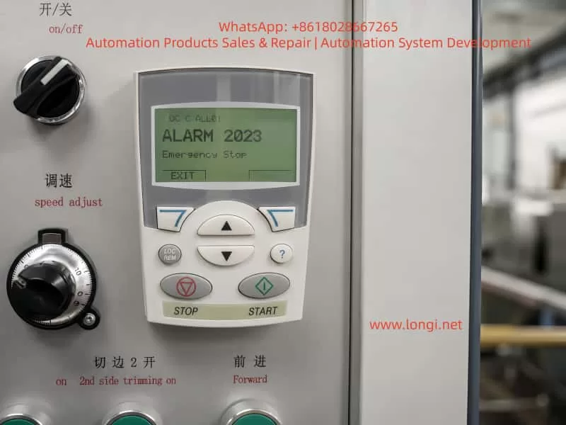
ABB ACS550 drives are widely used in these applications because they support analog inputs, digital inputs, relay outputs, PID functions, external reference control, and fieldbus communication. However, when an ACS550 receives an unstable analog reference through AI1, the result can be much more serious than a simple speed fluctuation.
Typical field symptoms include:
- The drive operates normally after reset.
- After several hours, one drive begins to slow down or stop unexpectedly.
- The AI1 signal fluctuates between abnormal values.
- The displayed speed reference or percentage suddenly decreases.
- The machine loses synchronization with other motors.
- Other drives show a certain monitoring value, but one drive does not.
- The production line stops even though the main power section of the drive appears normal.
These symptoms are often misunderstood as an internal VFD hardware failure. In practice, the root cause is frequently related to the analog signal chain, wiring, grounding, parameter configuration, sensor feedback, signal conversion, electromagnetic interference, or differences between drives in the same synchronization system.
This article explains how to diagnose AI1-related instability in ABB ACS550 drives, how to distinguish external signal faults from internal drive faults, and how to improve the control system for reliable long-term operation.
1. Understanding the Role of AI1 in an ACS550 System
AI1 means Analog Input 1. In ABB ACS550 applications, AI1 may be used for:
- Speed reference input
- Process setpoint input
- Pressure reference
- Tension reference
- PID feedback or setpoint
- External potentiometer input
- PLC analog output input
- Signal converter output
- Sensor-based speed reference
The analog signal may be one of the following:
- 0–10 VDC
- 0–20 mA
- 4–20 mA
- A voltage signal generated by an external controller
- A current signal generated by a PLC analog output module
- A signal converted from encoder or proximity sensor pulses
- A process signal from a transmitter or sensor
In a simple fan or pump application, a small fluctuation in AI1 may only create a minor speed change. However, in a multi-motor synchronized production line, the analog reference often affects the speed relationship between several motors.
For example:
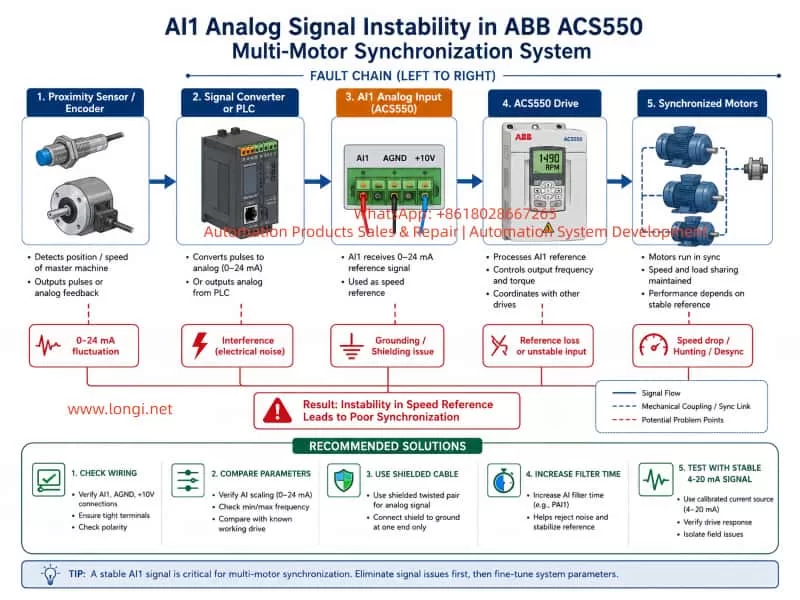
Proximity Sensor / Encoder
        ↓
Pulse Signal
        ↓
Pulse-to-Analog Converter or PLC High-Speed Counter
        ↓
0–10 V or 4–20 mA Speed Reference
        ↓
ACS550 AI1 Input
        ↓
Drive Frequency Reference
        ↓
Motor Speed
        ↓
Multi-Motor Synchronization
If the AI1 signal becomes unstable, the VFD does not know whether the machine really needs to speed up, slow down, or stop. It simply follows the changing reference value.
This is why AI1 stability is critical in synchronized motor systems.
2. Typical Fault Symptoms and What They Mean
2.1 The drive works after reset, then fails again after several hours
This is one of the most important symptoms.
When a drive works correctly after reset but becomes unstable later, the fault is often related to one of the following:
- Heat-related signal drift
- Loose wiring terminals
- Sensor output instability
- Power supply voltage variation
- 24 VDC control supply instability
- Analog signal converter overheating
- Electrical noise increasing during production
- Ground potential changes
- Vibration-related intermittent contact
- Parameter switching caused by digital inputs
- External control logic changing under certain machine conditions
A completely failed power module, IGBT section, or main control circuit often causes a more permanent and repeatable fault, such as:
- Overcurrent trip
- Output phase failure
- DC bus overvoltage
- DC bus undervoltage
- Permanent fault code
- No output voltage
- Inability to start
- Abnormal motor current
- Repeated trip immediately after power-up
Therefore, a fault that disappears after reset and returns only after hours of operation should first be investigated as a control signal, wiring, sensor, or parameter issue.
2.2 AI1 signal fluctuates between 0 mA and 24 mA
For most industrial current-loop applications, the expected signal range is usually:
- 0–20 mA, or
- 4–20 mA.
If AI1 is observed fluctuating from 0 mA to 24 mA, this is not normal and must be investigated.
Possible meanings include:
- 0 mA may indicate a broken signal wire.
- 0 mA may indicate transmitter power loss.
- 0 mA may indicate an open current loop.
- 0 mA may indicate an incorrect reference connection.
- More than 20 mA may indicate an over-range condition.
- More than 20 mA may indicate signal converter failure.
- More than 20 mA may indicate incorrect 24 V wiring.
- More than 20 mA may indicate a common-ground problem.
- Random fluctuation may indicate electrical interference.
- Random fluctuation may indicate poor terminal contact.
- Random fluctuation may indicate a sensor or converter that becomes unstable when warm.
When AI1 controls speed, the fault path is usually:
AI1 Signal Fluctuation
        ↓
Frequency Reference Changes
        ↓
VFD Output Frequency Changes
        ↓
Motor Speed Changes
        ↓
Synchronization Error Increases
        ↓
Mechanical Instability or Production Stop
The drive is not necessarily malfunctioning. It may simply be responding correctly to an incorrect or unstable command signal.
2.3 Speed percentage or frequency suddenly falls, then the machine stops
If AI1 is configured as the speed reference, the ACS550 calculates the target frequency from the AI1 value.
For example:
- 4 mA = 0 Hz
- 12 mA = 25 Hz
- 20 mA = 50 Hz
If the analog current suddenly drops from 12 mA to 4 mA, the VFD will interpret this as a command to reduce speed toward zero.
If the signal drops to 0 mA, the drive may interpret the situation as:
- Reference lost
- Very low speed command
- Signal fault
- External stop condition
- Analog input out of range
Depending on parameter configuration, the drive may:
- Decelerate to stop
- Hold the last valid speed reference
- Trigger a warning
- Trigger a fault
- Switch to another reference source
- Cause a synchronization error that stops the whole production line
Therefore, sudden speed drop does not automatically mean the motor, IGBT, or inverter output is defective. It may mean that the speed command itself has become unstable.
2.4 Other drives show a value, but one drive does not
A customer may say:
“Other drives show 112 value, but this drive is not showing.”
This information is important, but it must be interpreted correctly.
The number “112” may refer to:
- A monitored actual value
- A parameter number
- A process value
- An HMI display page
- A PLC register
- A fieldbus variable
- A custom mapped signal
- A speed reference monitoring value
It should not be assumed that “112” is always one fixed ACS550 parameter without confirming the exact menu, display page, parameter group, or engineering documentation.
However, if all other drives in the same system display the value correctly and only one drive does not, the most important action is comparison.
The faulty drive should be compared with a normal drive for:
- Control macro
- AI1 signal type
- AI1 scaling
- Reference source selection
- AI1 filtering
- Digital input functions
- Motor control mode
- Minimum and maximum frequency limits
- Communication settings
- I/O mapping
- PID settings
- Signal monitoring configuration
- Control panel display setup
This comparison is more reliable than blindly changing parameters.
3. Main Causes of AI1 Instability
3.1 Unstable signal source
The AI1 signal may come from:
- PLC analog output
- Proximity sensor signal converter
- Encoder frequency converter
- Tension controller
- Speed controller
- Process transmitter
- External potentiometer
- Signal isolator
- Sensor interface module
If the external signal source is unstable, the ACS550 cannot maintain stable speed.
A proximity sensor normally produces a pulse signal. It does not directly generate a smooth 4–20 mA or 0–10 V signal. Therefore, when a proximity sensor is used for speed reference, there is usually another device in the control chain, such as:
- Pulse-to-current converter
- Pulse-to-voltage converter
- Frequency-to-voltage converter
- PLC high-speed counter
- PLC analog output module
- Dedicated speed controller
This conversion stage is a common source of failure.
Typical faults include:
- Sensor supply voltage instability
- Sensor mounting movement
- Incorrect sensor gap
- Dirt, dust, oil, or metal particles on the sensing surface
- Weak pulse amplitude
- Pulse frequency outside converter range
- Converter overheating
- Converter output drift
- Loose output terminals
- Incorrect grounding
- Incorrect signal type configuration
If the pulse converter produces a fluctuating current output, the VFD will follow that fluctuation.
3.2 Incorrect analog wiring
ACS550 analog input wiring must be handled carefully. The drive contains terminals related to:
- Analog input
- Analog ground
- Signal shield
- +10 V reference
- +24 V control supply
- Digital input common
- Digital input terminals
Common wiring mistakes include:
- AI1 negative terminal connected to the wrong common terminal
- Analog ground connected to digital ground incorrectly
- AI1 connected to +10 V reference terminal by mistake
- Signal shield connected at both ends
- Signal shield left floating
- External 24 V supply mixed with internal 24 V supply
- Analog cable routed together with motor output cable
- Analog cable routed near braking resistor wiring
- Poor terminal tightening
- Oxidized cable lugs
- Broken wire strands inside the insulation
- Multiple analog sources sharing an incorrect common return path
These problems may not be visible when the machine is stopped. They often appear only during full-speed operation, high current load, high temperature, or strong electromagnetic interference.
3.3 Electromagnetic interference
Electromagnetic interference is especially important in medium- and high-power VFD systems.
A 37 kW drive produces switching pulses at the output terminals. The motor cable, output contactors, brake circuits, relay coils, and nearby power equipment can all create electrical noise.
If the AI1 cable runs parallel to the U/V/W motor output cable, interference may be induced into the analog signal.
Recommended practices include:
- Use shielded twisted-pair cable for analog signals.
- Keep AI1 cable physically separated from motor output cable.
- Avoid long parallel runs with U/V/W cables.
- Ground cable shield according to the system design.
- Use one-end shield grounding where appropriate.
- Do not mix analog wiring and high-power wiring in the same cable duct.
- Use separate routing for control wires and power wires.
- Use stable isolated 24 VDC supply for sensors and converters.
- Install analog signal isolators when necessary.
- Check for ground potential differences between panels.
- Inspect relay coils, contactors, and solenoids for suppression circuits.
A 4–20 mA signal is more resistant to noise than a 0–10 V signal, but it is not immune to wiring faults, grounding errors, common-mode voltage, or poor signal conversion.
3.4 Parameter mismatch
In multi-drive synchronization systems, parameter consistency is essential.
If one drive has different configuration from the others, it may behave differently even when the wiring and sensor signal are identical.
Possible parameter-related problems include:
- AI1 configured as voltage input while receiving current input
- AI1 configured as 0–20 mA while the signal is actually 4–20 mA
- Incorrect minimum or maximum scaling
- AI1 not selected as the active speed reference
- Keypad reference selected instead of external reference
- AI2 selected instead of AI1
- Fixed frequency selected by digital input
- Reference source switching unexpectedly
- AI1 filter time too short
- Minimum frequency too high or too low
- PID function enabled unintentionally
- Digital input changes the reference source
- Control macro differs from other drives
- Signal-loss behavior differs from other drives
For this reason, the best practice is to use one correctly operating drive as a reference and compare the complete relevant parameter groups with the faulty drive.
4. How to Distinguish External Signal Faults from Internal VFD Faults
This is the most important part of diagnosis.
4.1 Test with local keypad control
Temporarily switch the drive to local control and set a fixed frequency from the keypad.
For example:
- 20 Hz
- 30 Hz
- 40 Hz
If the motor runs steadily under keypad control, this strongly suggests that:
- The power section is likely healthy.
- The motor output is likely healthy.
- The main DC bus is likely healthy.
- The issue is likely related to external reference, analog input signal, sensor feedback, or parameter configuration.
This does not prove that the drive is perfect, but it significantly reduces the probability of a major inverter hardware fault.
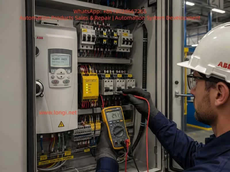
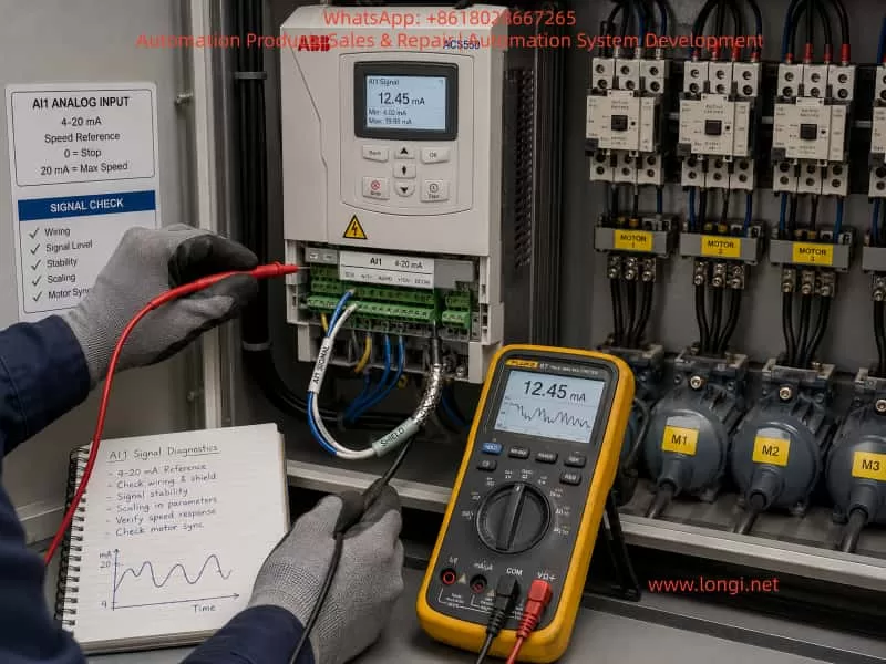
4.2 Monitor AI1 while the fault occurs
The AI1 value should be monitored under several operating conditions:
- Machine stopped
- Start-up
- Low-speed operation
- Normal production speed
- High-load operation
- After 30 minutes of operation
- Immediately before fault occurrence
- During the fault
- After reset
If the AI1 value changes randomly when machine speed should be stable, the fault is most likely in the signal chain.
A stable machine process should produce a stable speed reference.
4.3 Disconnect the external AI1 signal
With the machine safely stopped, disconnect the external AI1 signal from the drive and observe the monitored AI1 value.
Possible results:
| Result | Initial Conclusion |
|---|---|
| AI1 becomes stable at zero | External signal source or wiring is suspect |
| AI1 still fluctuates | Grounding, interference, or internal AI circuit may be suspect |
| AI1 does not return to expected value | Incorrect parameter type or internal circuit issue possible |
| Other input channels also fluctuate | Control board, grounding, or supply issue possible |
This test should only be performed by qualified personnel and only when the machine is in a safe condition.
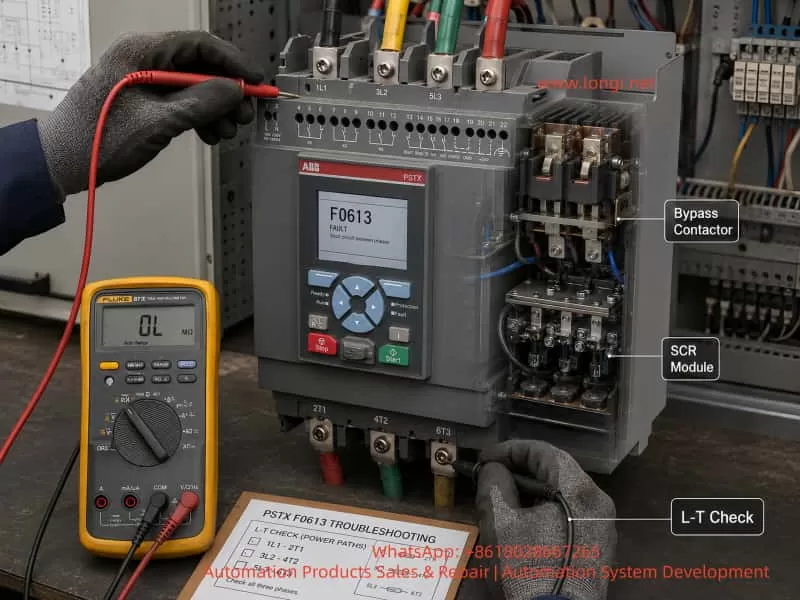
4.4 Use a standard 4–20 mA signal source
This is the strongest test for determining whether AI1 hardware is defective.
Use a reliable calibrator, process signal generator, or known stable analog source to provide fixed values such as:
- 4 mA
- 8 mA
- 12 mA
- 16 mA
- 20 mA
Then observe whether the drive reads the signal consistently.
If the external test signal is stable but the ACS550 display jumps, drifts, or disappears, then the AI1 input circuit or control board becomes a serious suspect.
If the drive reads the standard signal correctly and remains stable, then the VFD AI1 hardware is probably normal. The real problem is likely outside the drive.
4.5 Compare with another working drive
If the system contains several ACS550 drives, comparison is extremely valuable.
Use a working drive as the standard and compare:
- Analog input wiring
- AI1 configuration
- External reference selection
- Control macro
- Digital input functions
- Frequency limits
- Acceleration and deceleration times
- Analog filtering
- Fault handling
- PID enable status
- Monitoring values
- Communication configuration
If the same external signal works correctly on another drive but not on the faulty one, then either:
- The faulty drive parameters are different, or
- The AI1 hardware of that drive is damaged.
5. Recommended Field Diagnostic Procedure
Step 1: Back up parameters before changing anything
Before modifying settings, record or back up:
- Motor data
- Control macro
- AI1 type
- AI1 scaling
- AI1 monitoring value
- External reference source
- Digital input functions
- Minimum frequency
- Maximum frequency
- Acceleration time
- Deceleration time
- Fault history
- PID settings
- Communication parameters
In a multi-motor synchronization system, random parameter changes can create serious mechanical or production problems.
Step 2: Confirm the actual signal type
Do not guess the signal type based only on the number of wires.
Confirm whether the source is:
- 0–10 V
- 0–20 mA
- 4–20 mA
- Pulse-to-voltage conversion
- Pulse-to-current conversion
- PLC analog output
- Potentiometer output
- Sensor transmitter output
Use the electrical drawing, device labels, converter model number, PLC program, and multimeter measurement to confirm the actual signal.
Step 3: Verify AI1 wiring
Check:
- AI1 positive terminal
- AI1 negative terminal
- Analog ground terminal
- Signal shield
- Sensor power supply
- Signal converter power supply
- Terminal screw tightness
- Cable condition
- Cable route
- Shield termination
- Separation from U/V/W output cables
Pay special attention to loose terminals. A wire that appears connected may still have poor contact due to oxidation, vibration, or insufficient tightening torque.
Step 4: Compare all relevant parameters with a normal drive
Do not compare only one parameter.
Compare the full signal chain:
External Signal
        ↓
AI1 Configuration
        ↓
Scaling
        ↓
Filter
        ↓
Reference Selection
        ↓
Speed Limit
        ↓
Acceleration / Deceleration
        ↓
Motor Output
A mismatch anywhere in this chain may cause unstable speed.
Step 5: Test local keypad operation
Operate the VFD from the keypad with a fixed frequency.
If the system becomes stable, focus on:
- AI1 signal
- Pulse converter
- Sensor
- PLC output
- Grounding
- External reference parameter
- Digital input switching logic
Step 6: Test with standard analog signal
Connect a stable test signal to AI1.
If AI1 remains stable, the external system is faulty.
If AI1 still fluctuates, investigate:
- AI1 internal circuit
- Analog ground
- Control board condition
- Electrical interference
- Internal power supply
- Control board temperature-related drift
6. Recommended Improvement Solutions
Solution 1: Improve the existing analog signal system
This is suitable when the customer wants the lowest-cost improvement.
Recommended actions:
- Replace AI1 cable with shielded twisted-pair cable.
- Keep analog cable away from motor output cables.
- Confirm shield grounding method.
- Correct analog ground connection.
- Tighten all terminals.
- Check sensor mounting condition.
- Check pulse-to-analog converter condition.
- Verify stable 24 VDC supply.
- Install analog signal isolator if required.
- Apply suitable analog input filtering.
- Configure reasonable behavior for temporary signal loss.
- Compare all parameters with a known-good drive.
This solution can significantly improve reliability when the root cause is wiring, interference, or weak signal conditioning.
Solution 2: Use PLC high-speed counter and controlled analog output
This is the preferred engineering solution when a proximity sensor or encoder is used for speed control.
A proximity sensor produces pulses. It is generally better to process those pulses in a PLC rather than feeding an unstable converted signal directly into a VFD analog input.
Recommended architecture:
Proximity Sensor / Encoder
        ↓
PLC High-Speed Counter
        ↓
Speed Calculation and Filtering
        ↓
Fault Detection and Signal Validation
        ↓
PLC Analog Output or Industrial Communication
        ↓
ACS550 Speed Reference
The PLC can provide:
- Pulse filtering
- Debounce logic
- Speed averaging
- Minimum and maximum limit
- Signal-loss detection
- Alarm generation
- Hold-last-value strategy
- Smooth acceleration and deceleration
- Ratio control for multiple motors
- Master-slave synchronization
- HMI display and trend recording
This structure provides much better stability than direct pulse-to-analog conversion.
Solution 3: Use communication instead of analog reference
For systems with multiple synchronized drives, communication control is often more reliable than analog control.
Possible communication methods include:
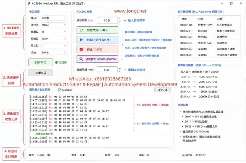
- Modbus RTU
- PROFIBUS DP
- CANopen
- DeviceNet
- EtherNet/IP
- PROFINET
- EtherCAT
Advantages include:
- Reduced analog signal interference
- Consistent speed reference for all drives
- Centralized parameter control
- Easier fault diagnosis
- Real-time monitoring of frequency, current, status, and faults
- Better synchronization capability
- Easier integration with PLC and HMI
- Improved traceability of production faults
Communication conversion should be engineered carefully. It should not be performed as a simple wiring replacement without reviewing PLC capability, network topology, response time, safety logic, and existing machine operation.
7. When Should the ACS550 Hardware Be Considered Faulty?
The VFD hardware should be suspected only after reasonable external tests are completed.
Possible indicators of AI1 internal hardware failure include:
- A stable calibrated 4–20 mA signal still causes AI1 fluctuation.
- AI1 fluctuates even when external wires are disconnected.
- AI1 has large reading error that cannot be corrected by normal scaling.
- The same external signal works correctly on another drive but not on this drive.
- Parameters and wiring are confirmed identical to a normal drive.
- Moving the signal to AI2 restores stable operation.
- The control board shows corrosion, moisture damage, burnt components, or abnormal heating.
- Other I/O points also behave abnormally.
- Parameters fail to save or become corrupted.
- AI1 becomes unstable only after the control board warms up.
If several of these conditions are confirmed, the repair path may include:
- Control board inspection
- AI input circuit repair
- Replacement of analog input conditioning components
- Replacement of the control board
- Replacement of the drive
- Temporary use of AI2 if system design permits
- Installation of external signal conditioner as an interim solution
8. Why Blind Parameter Changes Are Dangerous
When a customer requests: “Please tell me which parameters to change,” it is important not to guess.
A value shown as “112” may not be a universal ACS550 parameter. It may be a custom display, HMI register, monitored signal, or application-specific value.
Blindly changing reference parameters can cause:
- Unexpected acceleration
- Unexpected deceleration
- Motor reversal
- Loss of synchronization
- Excess tension
- Product damage
- Conveyor jam
- Mechanical shock
- Emergency stop
- Damage to coupled machines
Before changing parameters, always identify:
- The exact parameter number
- The parameter name
- The current value
- The value on a normal drive
- The control function connected to that parameter
- The safety impact of the change
The safest rule is:
Compare with a working drive first, then change only confirmed differences.
Conclusion
When an ABB ACS550 drive in a multi-motor synchronization system shows AI1 fluctuation, sudden speed reduction, stopping during operation, or missing monitoring values, the first assumption should not be that the VFD power section is defective.
The correct diagnostic sequence is:
Confirm the speed reference source
        ↓
Identify the AI1 signal type
        ↓
Monitor AI1 during operation
        ↓
Compare parameters with a normal drive
        ↓
Test keypad control
        ↓
Disconnect external AI1 signal
        ↓
Inject a stable standard analog test signal
        ↓
Only then evaluate AI1 hardware or control board failure
In most cases, the root cause is related to:
- Sensor instability
- Pulse-to-analog converter failure
- PLC output issue
- Incorrect analog wiring
- Grounding problem
- Electromagnetic interference
- Parameter mismatch
- Reference source switching
- Analog input scaling issue
- Inadequate signal filtering
For long-term reliability, systems using a proximity sensor or encoder for multi-motor synchronization should ideally use a PLC high-speed counter, signal validation logic, filtering, and either stable analog output or industrial communication to the drives.
This approach reduces speed-reference instability, improves synchronization accuracy, simplifies troubleshooting, and helps prevent unexpected production stoppages.