Posted on Leave a comment

User Manual Guide for Delta VFD-VE Series

The Delta VFD-VE series is a high-performance variable frequency drive widely used in various industrial automation scenarios. This article provides a detailed guide on the operation panel functions, parameter settings, fault codes, and their solutions to help users effectively use and maintain this device.

VFD-VE正面图

Operation Panel Functions

Operation Panel Features

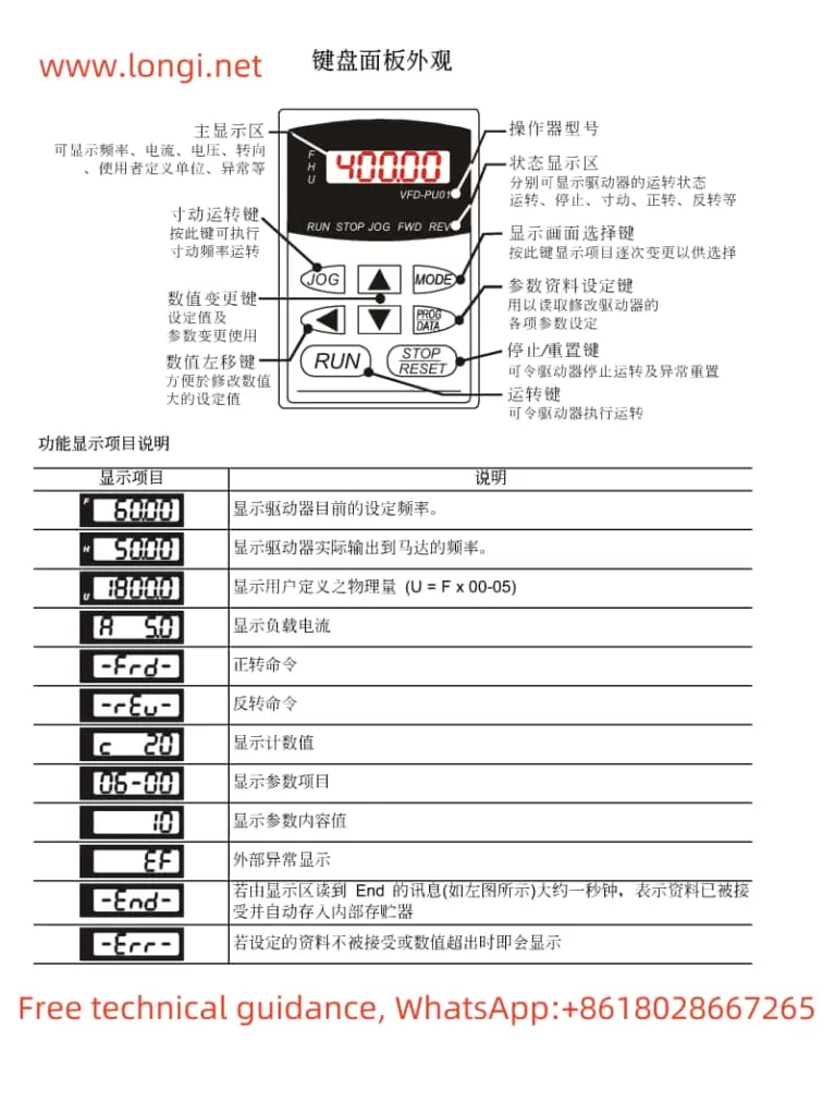
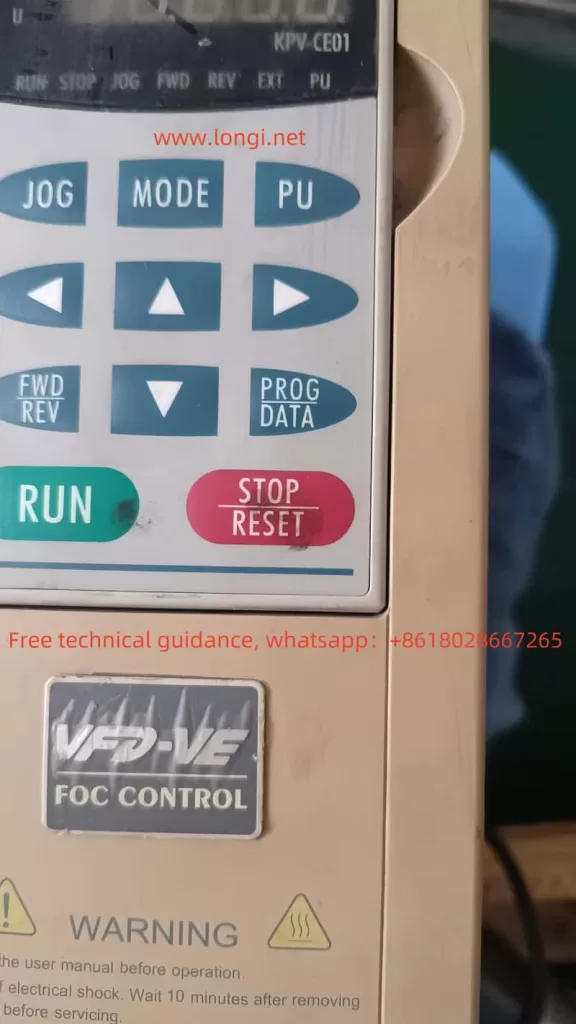
The operation panel of the Delta VFD-VE series is primarily composed of the digital operator KPV-CE01, which offers rich display and operation functions. Users can perform parameter settings, run control, and fault diagnosis through the panel. The main functions include:

  1. Parameter Settings: Users can set various parameters such as frequency, voltage, and current via the operation panel.
  2. Run Control: The panel provides basic run control functions such as start, stop, forward, and reverse.
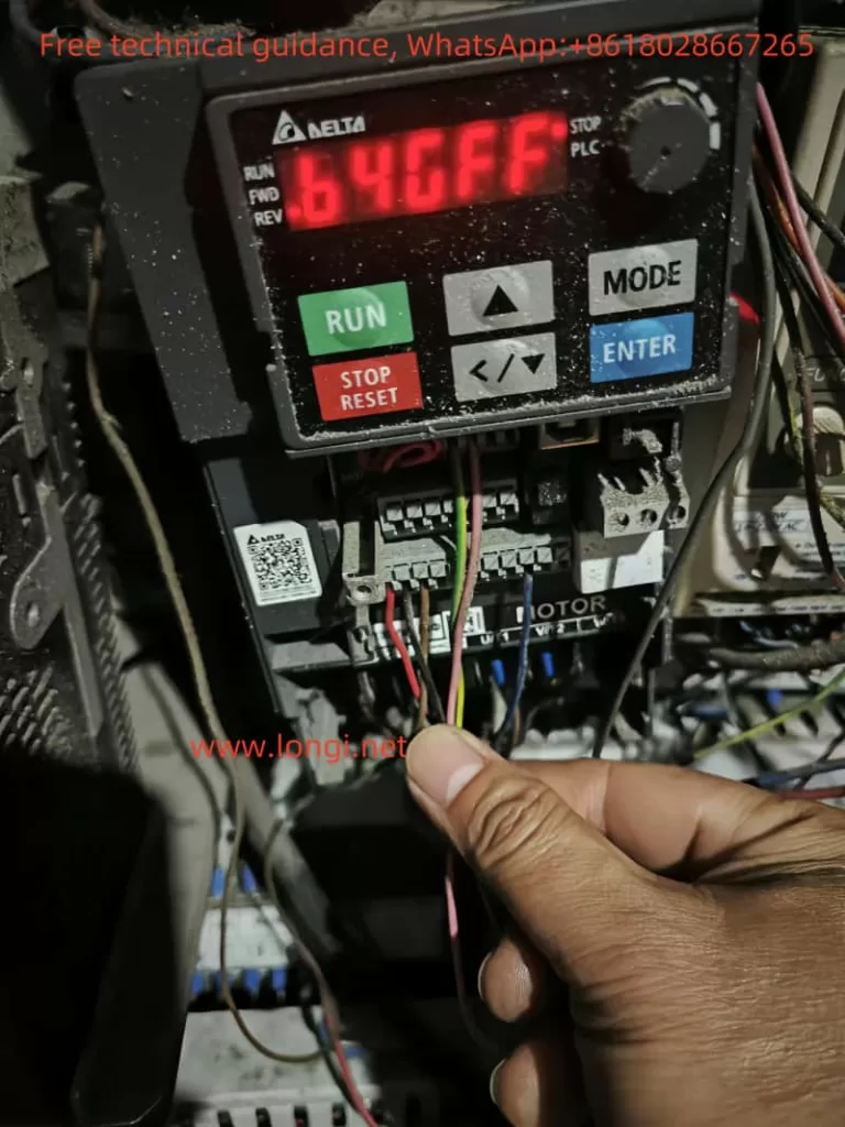
  3. Fault Diagnosis: When a fault occurs, the panel displays the corresponding fault code to help users quickly identify and resolve issues.

Parameter Initialization

To restore the drive to its factory settings, follow these steps:

  1. Enter the parameter setting interface and locate parameter 00-02.
  2. Set parameter 00-02 to 9 (restore factory settings with a base frequency of 50Hz) or 10 (restore factory settings with a base frequency of 60Hz).
  3. Confirm the setting to reset all parameters to their default factory values.

Parameter Copying

To copy parameters from one drive to another, follow these steps:

  1. Use the parameter copy function of the digital operator KPV-CE01 to export and save the current drive’s parameters.
  2. Import the saved parameter file into the target drive to complete the parameter copying process.

Setting and Removing Passwords

To protect the drive’s parameter settings, users can set a password to restrict access:

  1. Enter the parameter setting interface and locate parameter 00-08.
  2. Input a 4-digit password. Once set, the parameters will be locked.
  3. To remove the password, set parameter 00-08 to 0.

Parameter Access Restriction

Users can restrict access to parameters by setting parameter 00-07:

  1. Enter the parameter setting interface and locate parameter 00-07.
  2. Input a 4-digit access code. Once set, only users who know the access code can modify the parameters.

External Terminal Control

Forward and Reverse Control via External Terminals

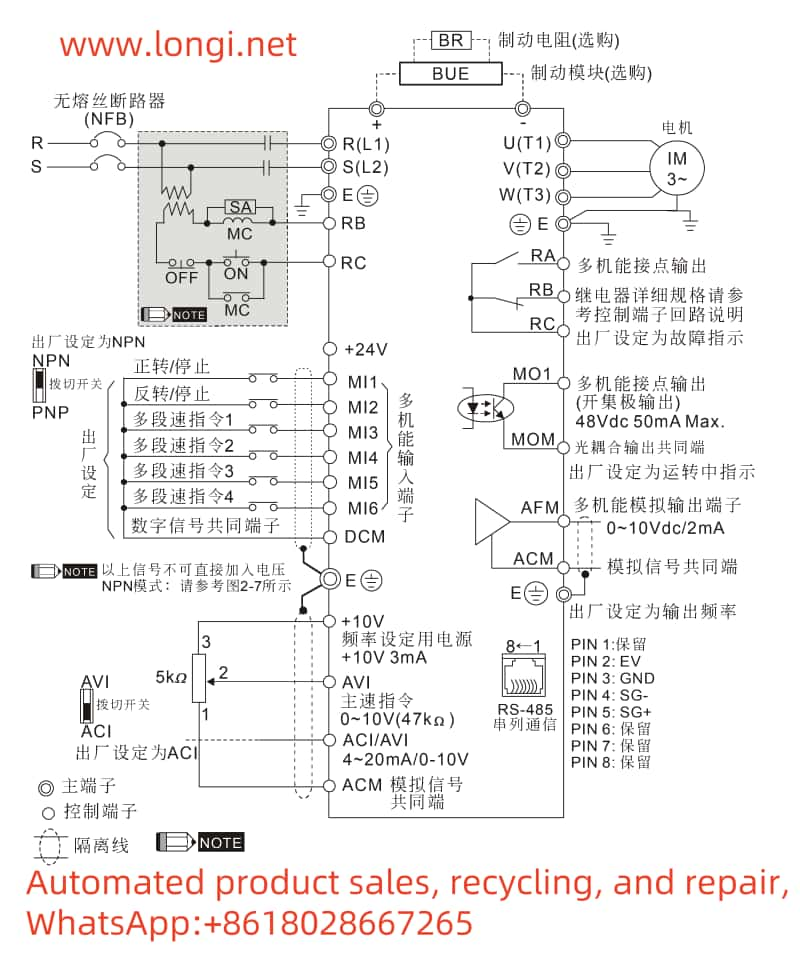
To implement forward and reverse control via external terminals, set the following parameters:

  1. Parameter 00-23: Set to 0 (forward and reverse allowed), 1 (reverse prohibited), or 2 (forward prohibited).
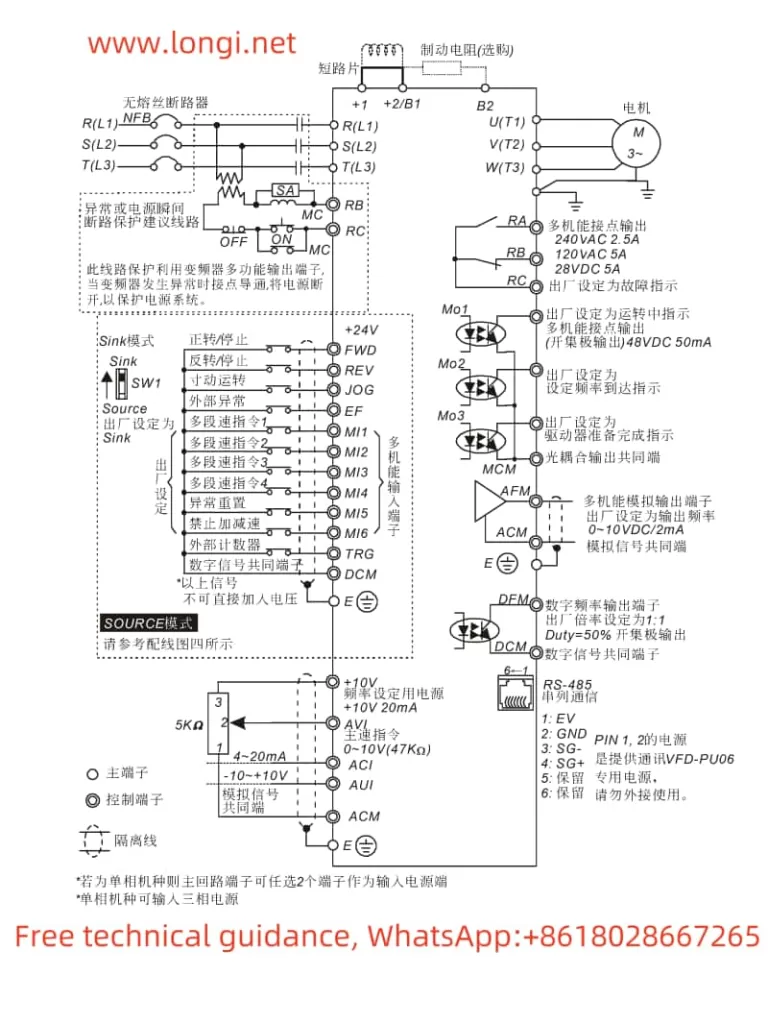
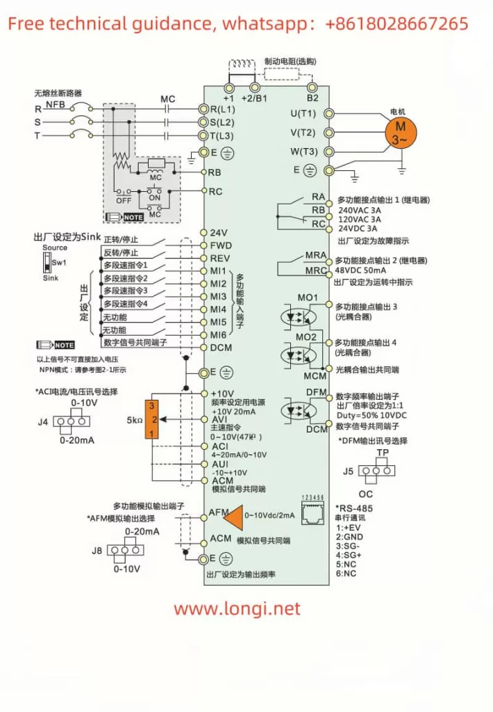
  2. Terminal Connections: Connect the external control signals to terminals FWD (forward) and REV (reverse).

Frequency Control via External Potentiometer

To achieve frequency control via an external potentiometer, set the following parameters:

  1. Parameter 00-20: Set to 2 (frequency controlled by external analog input).
  2. Terminal Connections: Connect the output signal of the external potentiometer to terminal AVI (analog voltage frequency command).

Fault Codes and Solutions

The Delta VFD-VE series may encounter various faults during operation. Here are some common fault codes and their solutions:

  1. OC (Overcurrent): Indicates that the drive has detected an overcurrent, possibly due to excessive load or motor failure. The solution is to check the load and motor status, reducing the load or replacing the motor if necessary.
  2. OV (Overvoltage): Indicates that the drive has detected an overvoltage, possibly due to a high source voltage. The solution is to check the source voltage and ensure it is within the allowable range.
  3. LV (Low Voltage): Indicates that the drive has detected a low voltage, possibly due to a low source voltage. The solution is to check the source voltage and ensure it is within the allowable range.
  4. OH (Overheat): Indicates that the drive is overheating, possibly due to poor heat dissipation or high ambient temperature. The solution is to check the heat dissipation conditions and ensure the drive is in a well-ventilated environment.
  5. PHL (Phase Loss): Indicates that the drive has detected a phase loss, possibly due to a fault in the power supply line. The solution is to check the power supply line and ensure it is functioning correctly.
  6. GFF (Ground Fault): Indicates that the drive has detected a ground fault, possibly due to an internal wiring fault. The solution is to check the internal wiring and replace any faulty components if necessary.
VFD-VE standard wiring diagram

Conclusion

The Delta VFD-VE series is a powerful variable frequency drive that allows precise motor control through proper parameter settings and correct operation. This guide provides detailed information on the operation panel functions, parameter settings, fault codes, and their solutions to help users effectively use and maintain this device. In practical applications, users should set the drive’s parameters according to specific needs and environmental conditions to ensure stable and reliable operation.

Posted on Leave a comment

Delta VFD-E Series Inverter User Manual Operation Guide

I. Introduction to the Panel Functions and Operations of the Delta VFD-E Series Inverter

VFD-E inverter

Panel Function Introduction

The panel of the Delta VFD-E series inverter primarily consists of the following function keys and display areas:

  • Power Indicator: Indicates whether the inverter is powered on.
  • RUN Indicator: Indicates the running status of the inverter.
  • FREQ Display: Displays the current operating frequency of the inverter.
  • MODE Key: Switches between different modes for parameter setting and monitoring.
  • ▲/▼ Keys: Used for increasing or decreasing parameter values or frequency settings.
  • STOP Key: Stops the operation of the inverter.
  • RESET Key: Resets the inverter to its initial state or clears fault alarms.
  • ENTER Key: Confirms the setting of parameters.
  • JOG Key: Enables jogging (inching) operation of the motor.
  • FWD/REV Keys: Controls the forward and reverse rotation of the motor.

Panel Operations

Copying Parameters to Another Inverter

  1. Connect to the Inverter: Use a suitable communication cable to connect the source inverter (containing the desired parameters) to the target inverter.
  2. Enter Copy Mode: On the source inverter, press the MODE key until the “Copy” mode is displayed.
  3. Initiate Copy: Press the ENTER key to initiate the parameter copy process.
  4. Complete Copy: Follow the prompts on the display to complete the parameter copy. Disconnect the communication cable after copying is finished.

Setting and Removing Passwords

Setting a Password:

  1. Navigate to the parameter group 00 User Parameters.
  2. Select parameter 00-08 Parameter Protection Password.
  3. Enter the desired password value (00-65535).
  4. Press ENTER to confirm.

Removing a Password:

  1. Navigate to the parameter group 00 User Parameters.
  2. Select parameter 00-08 Parameter Protection Password.
  3. Enter the password value you want to remove (set it to 00).
  4. Press ENTER to confirm.

Resetting to Factory Defaults

  1. Navigate to the parameter group 00 User Parameters.
  2. Select parameter 00-02 Parameter Reset Setting.
  3. Set the value to 09 for resetting to factory defaults at 50Hz, or 10 for resetting to factory defaults at 60Hz.
  4. Press ENTER to confirm and restart the inverter to apply the reset.
Delta VFD-E inverter standard wiring diagram

II. Terminal Control for Forward/Reverse Start and Stop

Terminal Control Configuration

  1. External Terminal Connection: Connect the external control terminals (FWD, REV, STOP) to the corresponding terminals on the inverter.
  2. Parameter Configuration:
    • Navigate to the parameter group 02 Operation Mode Parameters.
    • Set parameter 02-01 First Operation Command Source to 01 (External Terminal).
    • Set parameter 02-05 Two-Wire/Three-Wire Control to the desired control mode (e.g., 00 for two-wire control).
  3. Control Logic:
    • Forward Rotation: Close the FWD terminal and open the REV terminal.
    • Reverse Rotation: Close the REV terminal and open the FWD terminal.
    • Stop: Open both the FWD and REV terminals.

Monitoring and Troubleshooting

  • Monitoring: Use the inverter panel or an external monitoring device to check the operating status and parameters.
  • Troubleshooting: Refer to the inverter’s fault codes and troubleshooting guide in the user manual to diagnose and resolve issues.

By following the above steps, users can effectively operate and configure the Delta VFD-E series inverter for various applications, including terminal control for forward/reverse start and stop, parameter copying, password setting/removal, and resetting to factory defaults.

Posted on Leave a comment

Analysis, Types, and Maintenance Solutions for Delta Inverter GFF Fault

I. Meaning and Internal Mechanism of Delta Inverter GFF Fault

When a Delta inverter reports a “GFF” fault code, it indicates a “Ground Fault” (GFF) has occurred at the output terminal. This fault typically involves issues with the output circuit, such as damage to the IGBT, a short circuit in the output, or problems with the driver circuit, particularly when using PC929 optocouplers.

Physical picture of Delta INVERTER MS300 series

II. Analysis of the GFF Fault Scenario Described

In the scenario provided, the Delta inverter reports a GFF fault immediately upon connecting the motor, but the fault disappears when the motor wires are disconnected and the inverter is started alone. This suggests that the issue lies with the motor or the connection between the motor and the inverter, rather than the inverter itself.

Possible Causes:

  1. Motor Wiring Issues:
    • Short circuit or ground fault in the motor wiring.
    • Poor connection or loose wires at the motor terminals.
  2. Motor Problems:
    • Internal short circuit or ground fault within the motor.
    • Insulation failure or damage in the motor windings.
  3. External Interference:
    • Electromagnetic interference from nearby equipment affecting the inverter’s output circuit.
  4. IGBT or Driver Circuit Damage:
    • Although less likely in this case (since the fault disappears without the motor), damage to the IGBT or driver circuit could still be a factor if there are underlying issues with the inverter’s output stage.
b4GFF fault

III. Steps for Troubleshooting and Maintenance

  1. Check Motor Wiring:
    • Ensure all motor wires are properly connected and tightened.
    • Inspect the wires for any signs of damage, wear, or short circuits.
  2. Insulation Resistance Test:
    • Perform an insulation resistance test on the motor to check for insulation failure.
  3. Disconnect and Reconnect Motor:
    • Disconnect and then reconnect the motor wires to ensure a good connection.
    • Use a multimeter to test for continuity and shorts between the motor wires and ground.
  4. Isolate the Motor:
    • Try running the inverter with a different motor (if available) to determine if the fault lies with the motor or the inverter.
  5. Check Inverter Output Circuit:
    • Inspect the inverter’s output circuit for any signs of damage, particularly around the IGBTs and driver circuitry.
    • Replace any damaged components if necessary.
  6. Consult the Manual and Technical Support:
    • Refer to the Delta Inverter manual for more detailed troubleshooting steps and fault codes.
    • Contact Delta technical support for assistance if the issue cannot be resolved.

IV. Conclusion

The GFF fault reported by the Delta inverter is likely related to the motor or its connection to the inverter. By systematically checking the motor wiring, performing insulation resistance tests, and isolating the motor, the root cause of the fault can be identified and resolved. If the fault persists, further inspection of the inverter’s output circuit may be necessary.

Posted on Leave a comment

User Manual Guide for Delta Inverter VFD-B Series

I. Operating Panel Function Description and Parameter Settings

1. Operating Panel Function Description

The Delta Inverter VFD-B series features an intuitive operating panel with various functions and a display screen. The panel includes buttons such as RUN, STOP, ▲ (frequency increase), ▼ (frequency decrease), MODE, and an LCD display to show current operating status and parameter settings.

Function diagram of Delta inverter operation panel

2. Restoring Factory Defaults

To restore the inverter to its factory default settings, follow these steps:

  1. Enter Parameter Setting Mode: Press the MODE button to enter parameter setting mode.
  2. Select User Parameters: Use the ▲ and ▼ buttons to select parameter group 00 (User Parameters).
  3. Select Parameter Reset: Continue using the ▲ and ▼ buttons to select parameter 00-02 (Parameter Reset Setting).
  4. Set Factory Defaults: Set the value of parameter 00-02 to 09 or 10, corresponding to different voltage and frequency factory default settings.
  5. Save and Exit: After confirming the settings, press the DATA button to save and exit parameter setting mode.

3. Setting and Removing Passwords

To protect the inverter’s parameter settings from unauthorized changes, you can set a password:

  1. Enter Password Setting: In parameter setting mode, select User Parameters in parameter group 00, then find parameter 00-08 (Parameter Protection Password Setting).
  2. Enter Password: Use the ▲ and ▼ buttons to input the desired password (00~65535).
  3. Confirm Password: Enter the same password again to confirm.

To remove an existing password, simply set the value of parameter 00-08 back to 00.

II. Terminal Start and External Potentiometer Speed Control Settings

To configure the inverter for terminal start and external potentiometer speed control, you need to set specific parameters and connect certain terminals:

1. Parameter Settings

  1. First Operation Command Source Setting: Set parameter 02-01 to 01, indicating that the operation command is controlled by external terminals.
  2. First Frequency Command Source Setting: Set parameter 02-00 to 01, indicating that the frequency command is controlled by the analog signal (0~10V) input from the external terminal AVI.
  3. Multi-function Input Command Setting: Depending on your needs, set parameters 04-04 to 04-09 to corresponding functions such as forward rotation, reverse rotation, start, stop, etc.

2. Terminal Connections

  1. Power Connection: Connect the inverter’s power terminals R, S, T to the three-phase AC power supply.
  2. Motor Connection: Connect the inverter’s output terminals U, V, W to the three-phase induction motor.
  3. Start and Stop Terminal Connection: Connect the external start button between the FWD terminal and the DCM terminal, and connect the stop button between the REV terminal and the DCM terminal (note that the connection method depends on the two/three-wire mode selection setting).
  4. External Potentiometer Connection: Connect the output of the external potentiometer between the AVI terminal and the GND terminal for speed control.
Delta VFD-B standard wiring diagram for frequency converters

III. Fault Codes, Their Meanings, and Solutions

The Delta Inverter VFD-B series will display corresponding fault codes when a fault occurs, allowing users to quickly locate the problem. Below are some common fault codes, their meanings, and solutions:

  1. OC (Overcurrent): Indicates that the output current of the inverter exceeds the rated value.
    • Solution: Check if the motor is overloaded, verify the motor wiring is correct, and adjust the acceleration and deceleration time parameters.
  2. OV (Overvoltage): Indicates that the DC bus voltage of the inverter is too high.
    • Solution: Check if the input power supply voltage is too high, ensure the braking resistor is connected correctly, and adjust the overvoltage protection parameters.
  3. OH (Overheat): Indicates that the internal temperature of the inverter is too high.
    • Solution: Check if the inverter installation environment is well-ventilated, ensure the cooling fan is working properly, reduce the load, or increase cooling measures.
  4. OL (Overload): Indicates that the motor is overloaded.
    • Solution: Check if the motor is operating under overload conditions, adjust the load, or increase the motor capacity.
  5. EF (External Fault): Indicates that an external fault signal has been input.
    • Solution: Check the source of the external fault signal and resolve the external fault.
  6. CF (Communication Fault): Indicates a communication anomaly.
    • Solution: Check if the communication lines are connected correctly and ensure the communication parameter settings are correct.

By following these steps, users can effectively use the Delta Inverter VFD-B series, including operating the panel, setting parameters, configuring functions, and troubleshooting faults. These operations will help users better control and maintain the inverter, ensuring its normal operation.