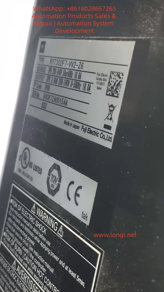
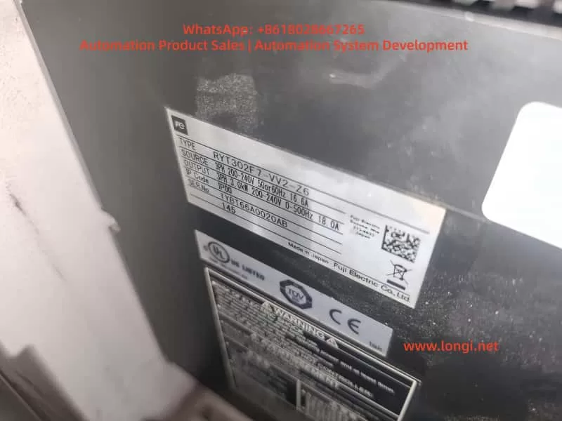
The Fuji ALPHA7 series servo drives, as Fuji Electric’s new generation of high-performance servo systems, are widely used in CNC machine tools, especially in positioning applications such as rotary tables and indexing tables. The VV-type universal interface (models like RYT302F7-VV2-Z6) supports multiple control methods including pulse, analog, positioning, and Modbus. It features a 3.0kW capacity, 200-240V three-phase input, and IP00 protection, suitable for GYS/GYB/GYG series motors. In actual field applications, drives often exhibit phenomena such as the keyboard displaying PSoF (Servo OFF), CNC screen READY signal flashing, and nG6 (Not Good 6) rejection to start during Test Operation Mode. These issues are not hardware failures but rather signal interlock problems caused by unmet servo startup permission conditions. This article systematically reviews the startup mechanism, display interpretation, fault diagnosis logic, troubleshooting process, parameter optimization, and preventive measures for ALPHA7 VV-type drives, providing a complete technical solution for field engineers.
I. Hardware and Interface Architecture of ALPHA7 VV-Type Servo Drives
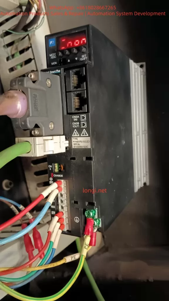
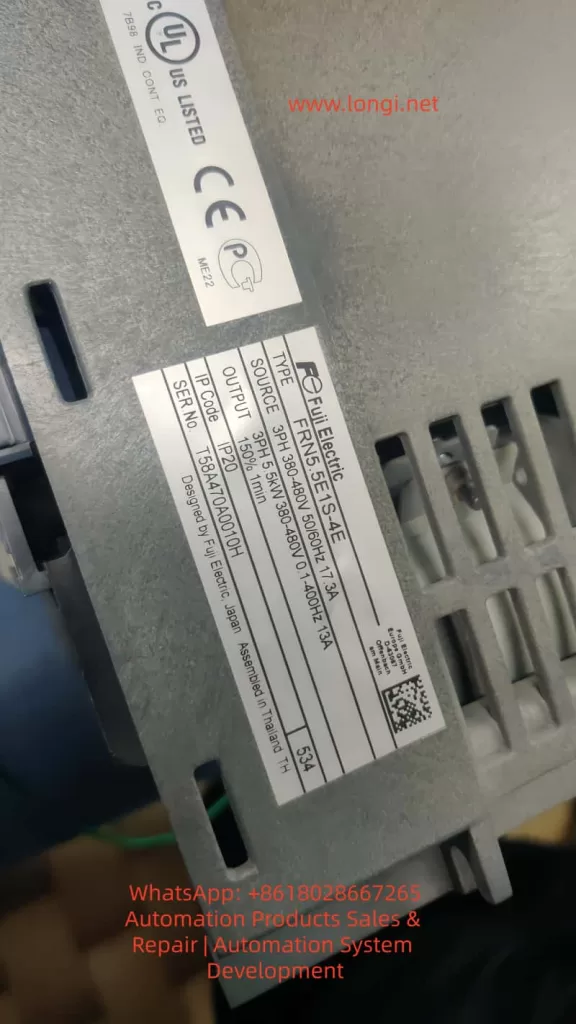
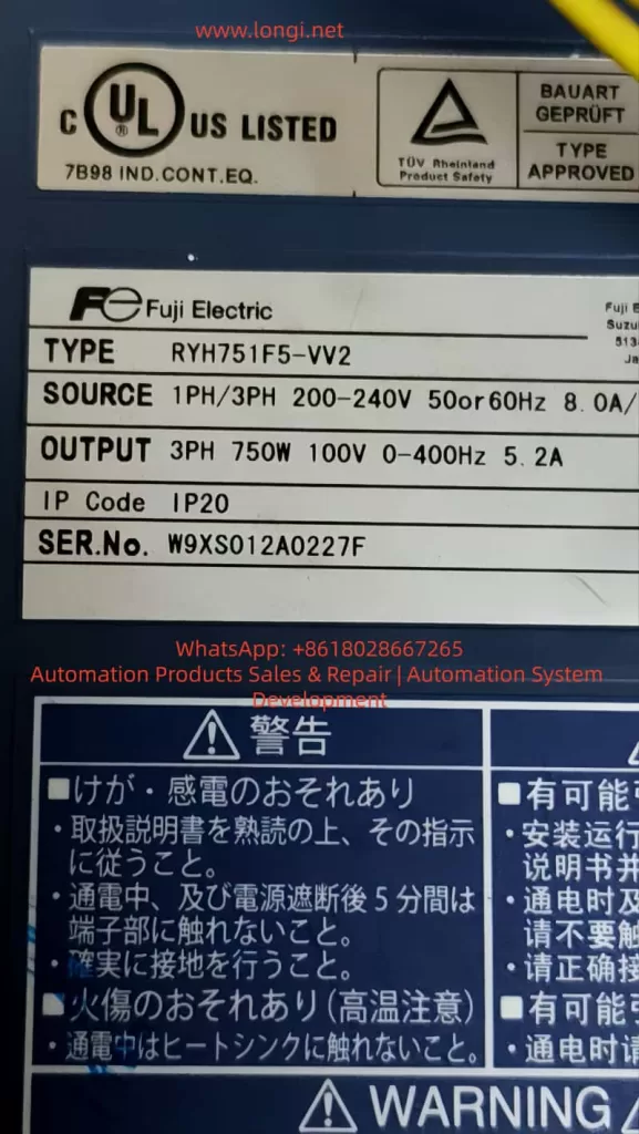
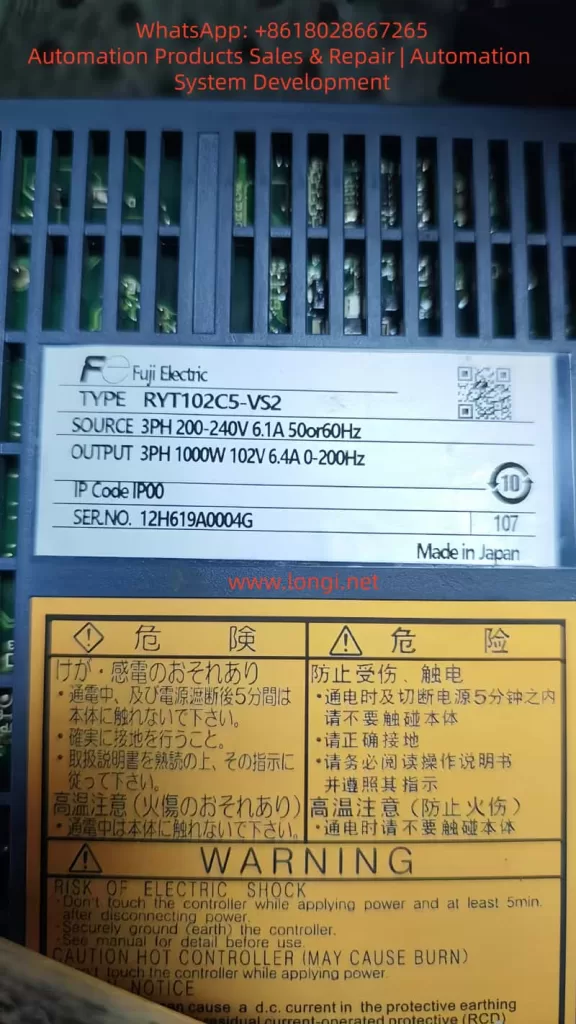
In the ALPHA7 series servo amplifier model number, RYT302F7-VV2-Z6 has a clear meaning: RYT denotes the ALPHA7 servo amplifier, 302F7 represents 3.0kW capacity (Frame 3 chassis) and 200V series, VV2 indicates the universal interface type (supports pulse/analog/positioning/Modbus), and Z6 is a specific market/batch suffix. The main circuit terminals of the drive include L1/L2/L3 main power supply, P1/P(+)/N(-) DC bus, and RB1/RB2/RB3 regenerative braking. The control power supply L1C/L2C is independently powered.
Key interfaces determine startup behavior:
- CN1: Main control signal interface, inputs S-ON (Servo ON), EMG (Emergency Stop), +OT/-OT (Overtravel), CONT1~8 (Sequence inputs, assignable to LOCK PIN, POSITIONING, etc.).
- CN6: Safety function interface (STO – Safe Torque Off). It must be correctly shorted or connected to the safety module WSU-ST1; otherwise, STO activation prevents the servo from turning ON.
- CN3A/CN3B: High-speed serial bus or expansion interface (VV-type is mainly used for external encoders or multi-axis synchronization).
- CN4: USB interface for real-time monitoring of signal status using PC Loader software.
- CN7: Keypad interface, supporting Sequence Mode and Test Operation Mode.
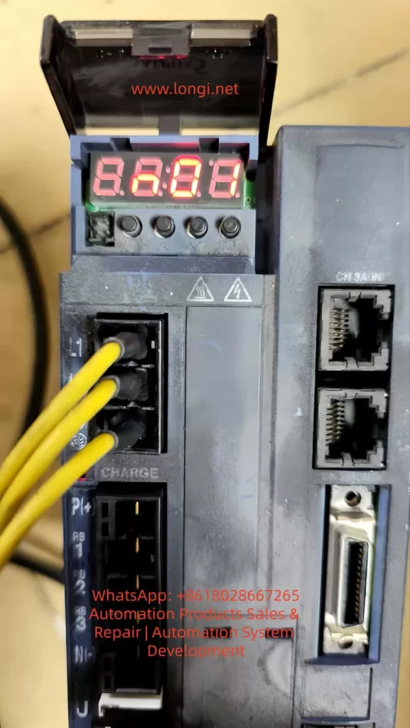
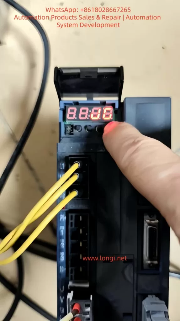
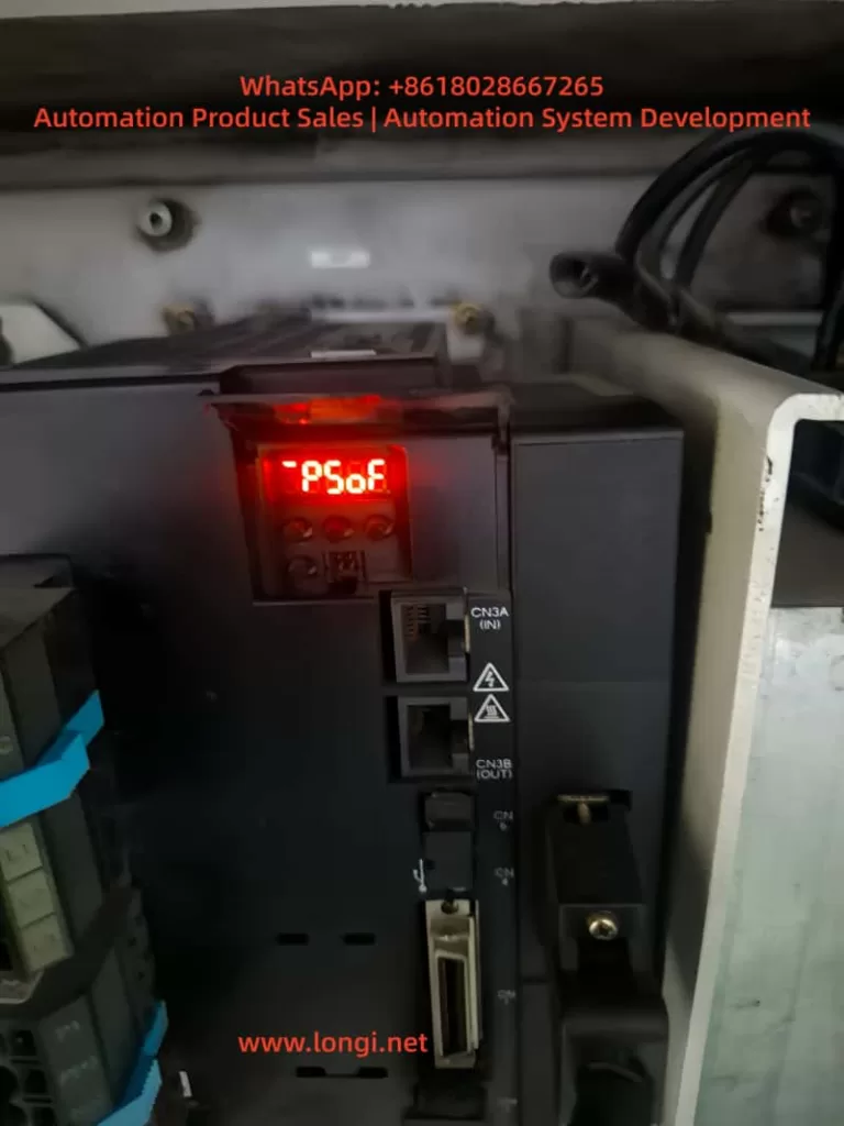
After the drive is powered on, if the internal self-test passes, it displays AL.0000 (No alarm). At this point, if the external S-ON signal is not input or the interlock conditions are not met, the keyboard defaults to #PSoF (or PSoF) in Sequence Mode, indicating the servo is off with no drive output. The CNC-side RDY (Ready) signal is fed back via CN1 output. If the drive does not enter the Servo ON state, the CNC screen READY signal flashes to indicate “Not Ready.” This architecture ensures safety but is also the most common source of “false faults.”
II. Keypad Display Modes and Status Interpretation
The ALPHA7 keypad supports multiple modes; Sequence Mode and Test Operation Mode are directly related to startup faults.
1. Sequence Mode (Sequence Mode)
The default mode upon power-up, displaying the real-time status of the servo.
- PSoF (#PSoF): Servo OFF, normal standby state. The servo motor has no current output, and the axis is in a free state.
- #PSon: Servo ON, powered on, the motor has holding torque.
- AL.0000: No alarm (confirm “No alarm at present” on the En_01 page).
- Er.0000: No error (common in Fn mode).
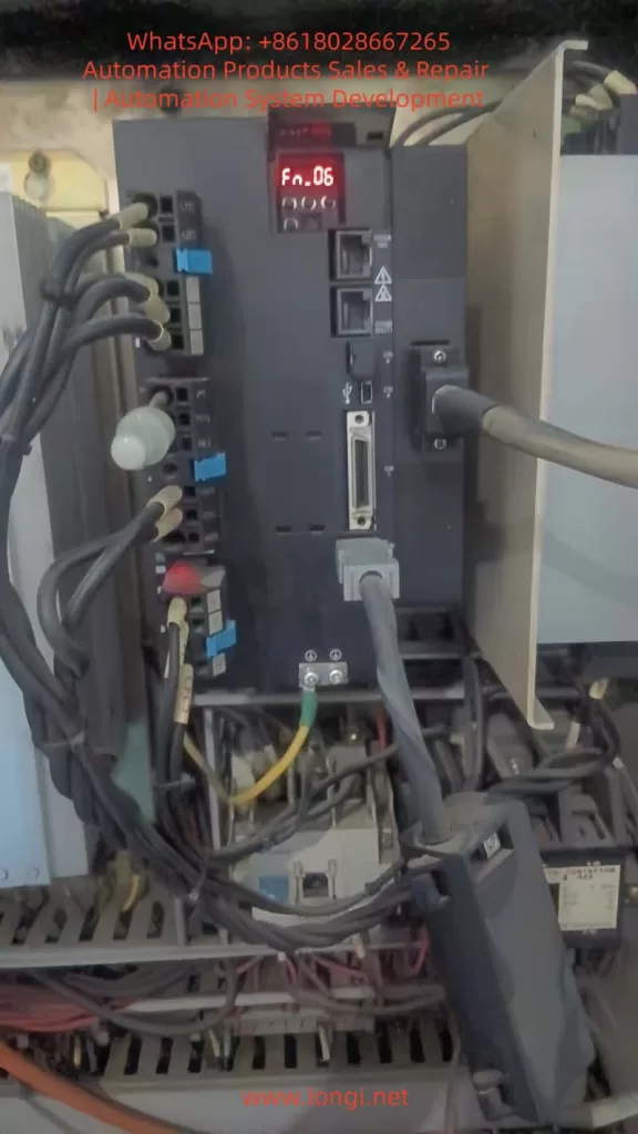
2. Test Operation Mode (Test Operation Mode, Fn_0n)
Entered via the MODE key; Fn_01 is for JOG, Fn_06 is for test run, etc.
- nG6 (Not Good 6): Prompt indicating that the operation start conditions are not met. The NG series codes mean “Cannot execute.” NG6 specifically refers to the lack of safety/interlock/signal permission (distinct from NG1 initialization failure, NG2 operation interruption, etc.). At this point, the drive refuses to output PWM, and the motor does not rotate.
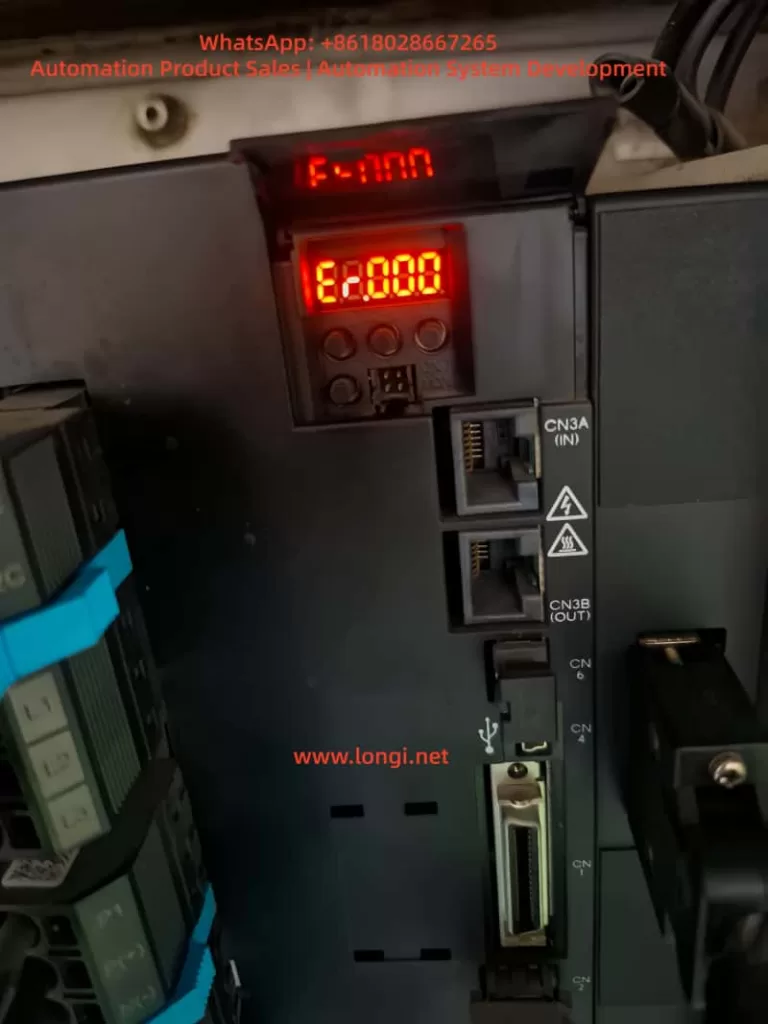
- F-nnn: Fn mode entry, Er.0000 indicates no error.
Keypad Operation Standard: Press MODE to enter the mode, use ↑↓ to select Fn, and press SET to confirm. If nG6 is displayed, it means S-ON is not valid, STO is not released, or CNC CONT signals are not ready. The ALPHA7 manual specifies: Before starting the Test Operation Mode, the Servo must be confirmed to be in the OFF state, and all external permission signals must be at valid levels.
III. Signal Interlock and READY Mechanism in CNC Integration
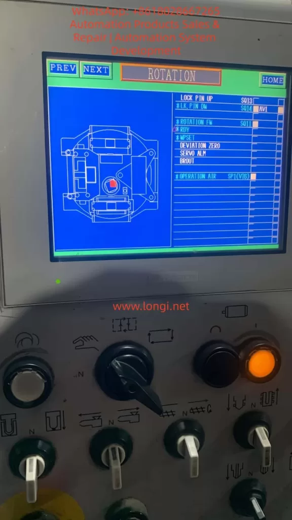
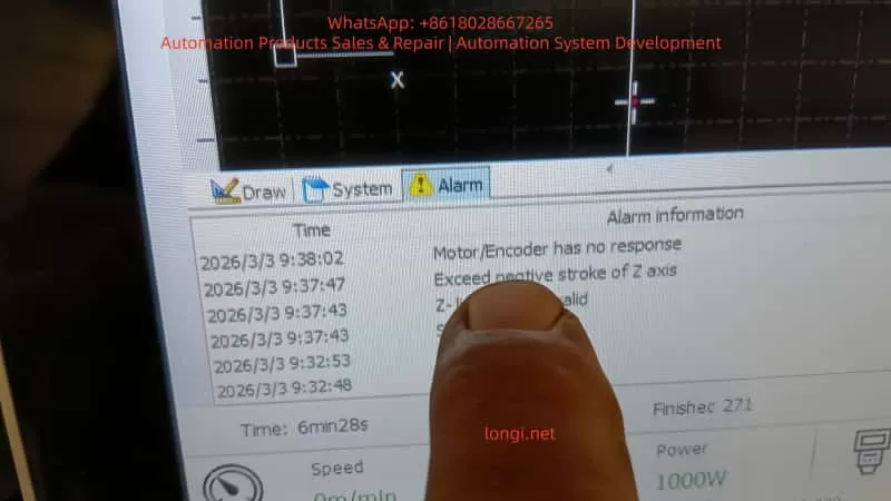
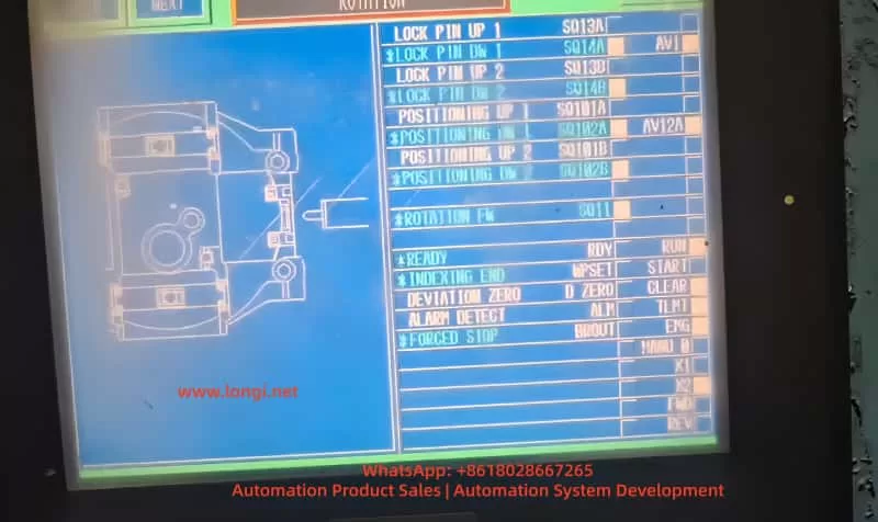
Typical CNC screen signals for rotary tables (LOCK PIN UP 1/2, POSITIONING UP 1/2, ROTATION Fb, READY, INDEXING END, ALARM DETECT, etc.) represent indexing control logic. The essence of READY flashing is that the CNC has not received the RDY output signal from the drive.
Signal Flow Analysis:
- CNC outputs S-ON to the corresponding terminal on CN1 (CONT signals can be assigned via PA3_01~08 parameters).
- Internal drive checks:
- Main power/control power is normal.
- STO (CN6) is not activated (safety module or shorted).
- EMG, +OT/-OT are OFF.
- Encoder feedback is normal (no P5 power loss, etc.).
- CONT sequence inputs meet application interlocks (e.g., LOCK PIN is in position, POSITIONING is complete).
- Once satisfied, the drive enters Servo ON and outputs RDY to the CNC.
- The CNC ladder logic then confirms all feedback signals, lighting up the READY indicator.
If any link is missing, the drive remains in PSoF, the CNC READY flashes, and nG6 appears during JOG. Common interlock points: Mechanical lock pin of the rotary table is not in position (LOCK PIN signal OFF), indexing position deviation (DEVIATION ZERO not ON), feedback pulse anomaly (ROTATION Fb missing). When the VV-type supports Modbus, also check the communication timeout parameter (PA2_95).
IV. Fault Phenomenon Diagnosis Logic
Interlocking of Three Phenomena:
- PSoF + AL.0000: Drive self-test passed, no hardware alarm.
- CNC READY Flashing: External signals are not in a closed loop.
- nG6 in Fn_01: Startup permission is missing in test mode.
Root Cause Classification:
- Signal Input Class (Most common, 70%): S-ON not output, CONT assignment error, CNC I/O card failure.
- Safety Function Class: STO activated (CN6 not shorted), EMG constantly ON, overtravel limit switch mistakenly triggered.
- Parameter/Configuration Class: PA3 sequence input assignment conflict, PA2_74 parameter write protection enabled, electronic gear ratio (PA1_06/07) causing feedback mismatch.
- Power/Wiring Class: Control power undervoltage (affects STO even without alarm), CN1 shielded wire poor grounding.
- CNC Logic Class: Ladder diagram READY trigger condition includes unmet indexing end signal.
Diagnostic Priority: Confirm AL.0000 on keypad first → Check CN6 STO → Monitor S-ON/CONT real-time status with PC Loader → Force S-ON output on CNC side for testing.
V. Practical Troubleshooting Process and Operation Standards (12-Step Complete Guide)
Tools Required: Multimeter, PC Loader software, ALPHA7 user manual, CNC ladder diagram.
Step 1: Power on and confirm the keypad displays AL.0000 and “No alarm” on En_01. If there is an AL.xx, refer to Chapter 7 of the manual for the alarm list and reset.
Step 2: Enter Sequence Mode to confirm PSoF. Record all current displays.
Step 3: Check CN6 STO terminals: If no safety module is used, 1-2 and 3-4 must be shorted; if a WSU-ST1 module is present, confirm 24V power supply and that PA safety function parameters are enabled.
Step 4: Measure the voltage at the S-ON terminal on CN1 (typically DC24V ON). If absent, force output via CNC I/O monitoring.
Step 5: Enter Test Operation Mode, select Fn_01 JOG. Press SET to start. If nG6 appears, record the prompt.
Step 6: Connect PC Loader to CN4 and monitor:
- S-ON input status (bit address).
- Actual levels of CONT1~8.
- RDY output status.
- STO status.
Step 7: Check mechanical interlocks: Whether the rotary table LOCK PIN is physically in position, and whether limit switch signals are conducting.
Step 8: Verify ladder logic on CNC side: Force S-ON and observe if READY lights up; check INDEXING END and DEVIATION ZERO signals.
Step 9: Parameter check: Confirm PA3_01~08 CONT assignments have no conflicts; set PA1_13 tuning mode to 0 (manual); disable PA2_74 write protection.
Step 10: Safety reset: Press SET/ESC on the keypad or use the CNC RST signal; power cycle the control power supply.
Step 11: Low-speed JOG test: Confirm motor rotation, no abnormal noise, and consistent position feedback.
Step 12: Full-speed test run: Monitor torque and speed waveforms, confirm no overload (PA2_70).
The entire process usually takes 30-60 minutes. Strictly adhere to: Disconnect main power before operation, wear anti-static protection, and ensure the emergency stop circuit is effective.
VI. Parameter Optimization, Safety Configuration, and Advanced Diagnostics
Key Parameter Optimization for VV-Type (for Rotary Tables):
- PA1_01: Select Control Mode 3 (Positioning Mode).
- PA1_05/PA1_06/07: Electronic gear ratio precisely matches the table reduction ratio.
- PA3_51~55: Assign RDY output signal to CNC.
- PA2_89/90: Encoder selection for sequence test mode (INC/ABS).
- Safety Parameters (WSU-ST1): Enable SS1/SLS/SBC functions, STO response time <10ms.
Advanced Diagnostics:
- PC Loader Waveform Recording: Record the delay from the rising edge of S-ON to RDY output.
- Life Prediction: ALPHA7 has built-in consumable life monitoring (capacitors, fans) for early warning.
- Multi-axis Synchronization: If using multiple VV-types, check that Modbus station numbers (PA2_72) do not conflict.
- Noise Suppression: Separate power and signal wiring by >30cm; use shielded cables for CN1 and ground them.
VII. Rotary Table Application Case Study
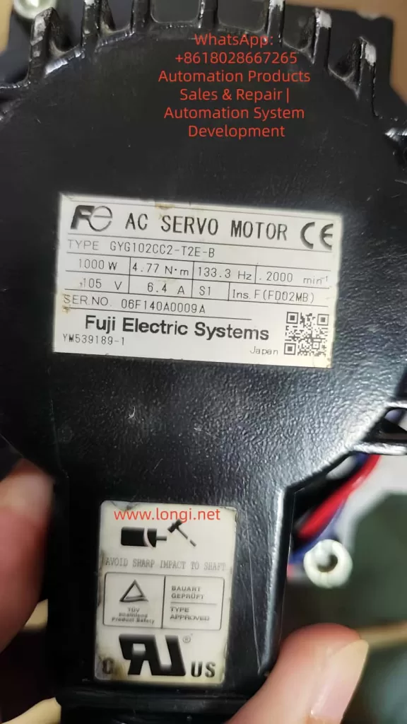
Field Case (RYT302F7-VV2-Z6 + GYS302D7 Motor):
- Phenomenon: Keypad PSoF, CNC READY flashing, Fn_01 JOG displayed nG6.
- Diagnosis: PC Loader showed S-ON input was OFF, and LOCK PIN UP signal was not ON (mechanical lock pin not reset).
- Solution: Adjusted the mechanical lock pin position, confirmed CONT signal assignment (PA3_03=LOCK PIN). After forcing S-ON, READY lit up and JOG was successful.
- Optimization: Added PA3_26~30 CONT constant ON function to improve anti-interference; enabled STO monitoring for daily self-checks.
In similar cases, 90% stem from unclosed interlock signals, 5% from STO wiring errors, and 5% from parameter assignment errors. No hardware damage was found in any case.
VIII. Preventive Maintenance and Best Practices
- Wiring Standards: Use twisted shielded cables for CN1/CN6, keeping them >30cm away from power lines.
- Power-up Sequence: Turn on control power first, then main power; when powering down, disconnect main power first.
- Regular Self-checks: Monthly Fn_05 alarm reset test and PC Loader signal scanning.
- Document Management: Save parameter backups (exported via PC Loader) and ladder diagram versions.
- Training Points: Operators are strictly prohibited from hot-swapping CN1; confirm PSoF before maintenance.
- Upgrade Suggestion: If nG6 occurs frequently, consider switching to LS-type with built-in positioning functions to reduce CNC load.
- Spare Parts Strategy: Keep CN6 shorting parts and STO modules in stock; do not disassemble the drive within the warranty period.
Adhere to ISO13849-1 Cat.3 PL-d safety standards to ensure the integrity of the STO function.
Conclusion
The PSoF, READY flashing, and nG6 phenomena in ALPHA7 VV-type drives are typical “signal permission not ready” faults. By interpreting the keypad display, tracing the signal flow, using PC Loader for monitoring, and following the 12-step troubleshooting process, production can be restored in the shortest possible time. The core lies in understanding the closed-loop logic of S-ON and multiple interlocks, rather than blindly replacing hardware. This guide is compiled based on the ALPHA7 user manual (Sequence Mode/Test Operation Mode chapters), field VV-type application experience, and safety module manuals, and is applicable to most CNC rotary table scenarios. In actual operation, strictly follow the latest manual version; for difficult problems, provide the serial number and Loader screenshots to Fuji Electric technical support for further diagnosis.
Mastering the above techniques can reduce the troubleshooting time for ALPHA7 startup faults from hours to minutes, improving equipment utilization and system reliability. In the future, with the popularization of EtherCAT VC-type drives, similar signal interlock issues will be further simplified, but the basic diagnostic logic remains unchanged. It is recommended that engineers establish a standardized troubleshooting checklist to ensure S-ON signal verification and STO function tests are completed for each device before commissioning.