I. Basic Operation and Monitoring Functions
- Panel Setting and Monitoring
Setting to Display Current, Bus Voltage, and Frequency
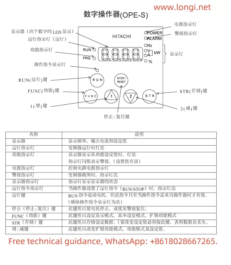
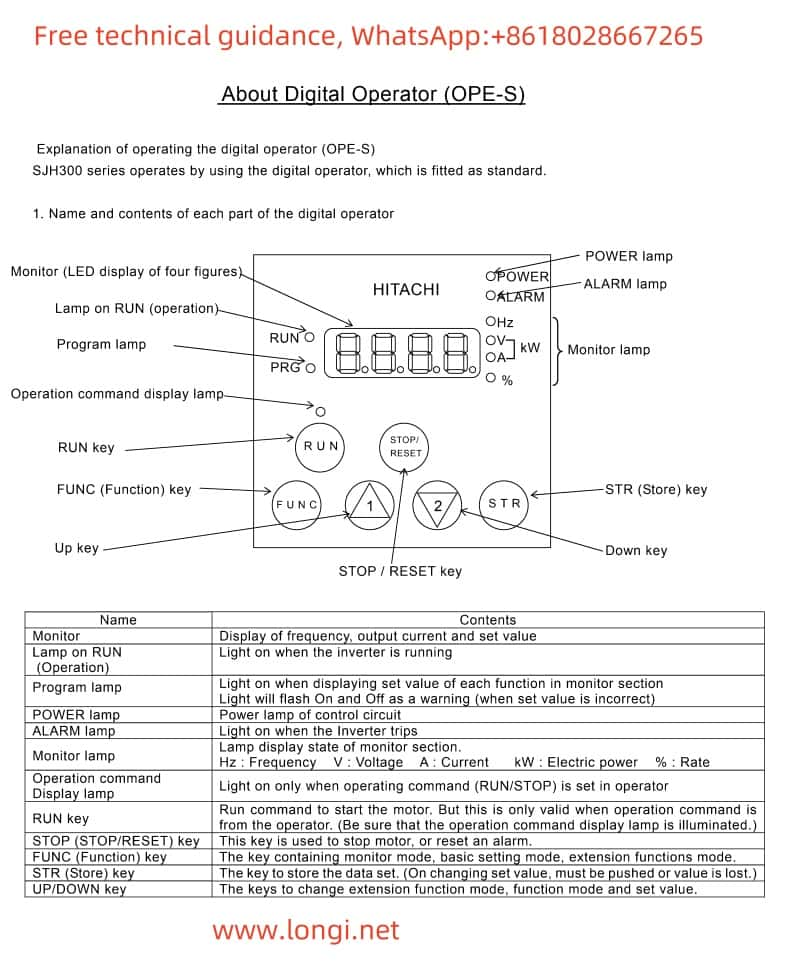
Display Current: First, enter the monitoring mode via the panel buttons (typically by selecting the monitoring mode with the “FUNC” key). In monitoring mode, use the up and down arrow keys to browse through different monitoring parameters, find the current monitoring item, and confirm.
Display Bus Voltage: Similarly, in monitoring mode, use the up and down arrow keys to find the bus voltage monitoring item and confirm.
Display Frequency: Frequency is one of the most commonly used monitoring parameters and is usually directly displayed on the main interface of the monitoring mode. If not displayed, select the frequency monitoring item with the arrow keys.
Monitoring Terminal Status
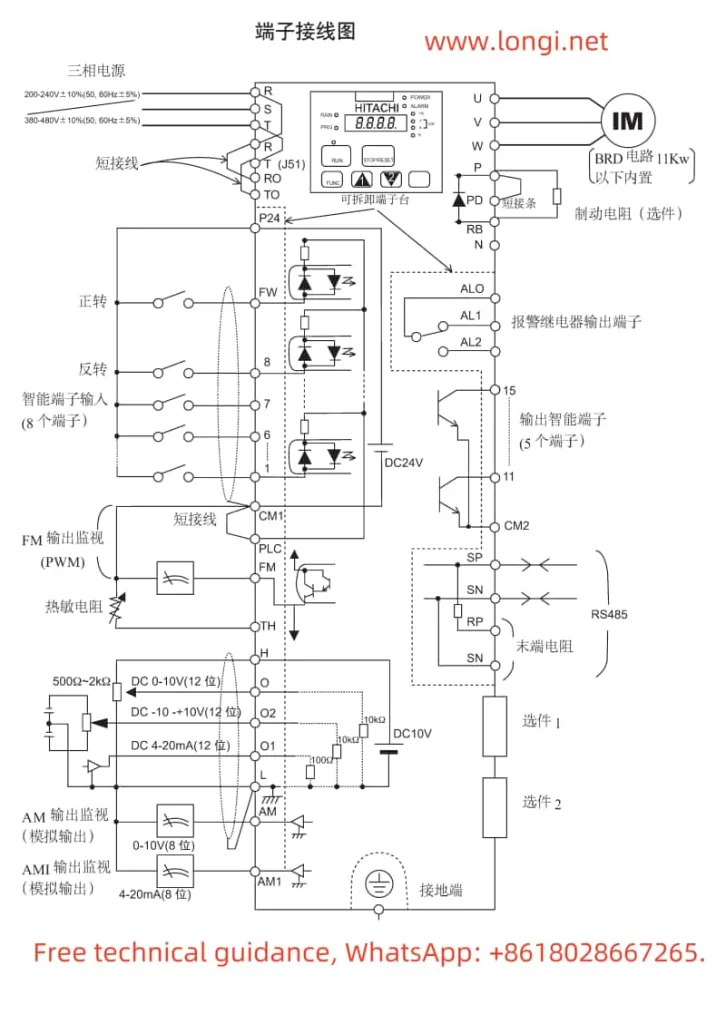
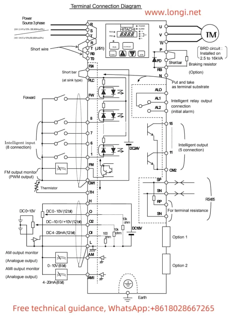
Enter monitoring mode, then select “Smart Input Terminal Status” or “Smart Output Terminal Status” for monitoring. These statuses include the switching state of the terminals, signal voltage, etc.
Panel Start/Stop and Speed Adjustment

Start and Stop: In standard setting mode, start the inverter with the “RUN” key and stop it with the “STOP/RESET” key.
Speed Adjustment: Speed adjustment is typically achieved by changing the frequency setting value. On the panel, use the up and down arrow keys to adjust the frequency setting value, then press the “Store” key to confirm.
II. Multi-Speed Function Setting
- Setting Multi-Speed
Assuming four speeds are needed, namely 10Hz, 20Hz, 40Hz, and 50Hz, the specific steps are as follows:
Wiring:
Connect external control signals (such as switch signals) to the inverter’s multi-speed control terminals (such as FW, 8, 7, 6, etc.).
Ensure correct connection of the control signal power supply and grounding.
Parameter Setting:
Enter standard setting mode and find parameters related to multi-speed control (such as A038, A039, etc.).
Set A038=00 (indicating external terminal control for multi-speed).
Set A039=04 (indicating 4-speed control).
Set the corresponding frequency values for the four speeds in the “F001” parameter: F001=10Hz (first speed), A020=20Hz (second speed), A220=40Hz (third speed), A320=50Hz (fourth speed).
III. Communication Protocol Setting

- Communication with Mitsubishi FX2N Series PLC
Communication Method: Assuming RS485 communication is used.
Parameter Setting:
In the inverter, set C070=03 (select RS485 communication).
Set C071 to the desired baud rate (e.g., C071=04 for 4800bps).
Set C072=1 (8 data bits).
Set C073=7 (no parity check).
Set C074=0 (1 stop bit).
On the PLC side, configure the corresponding RS485 communication parameters to match the inverter.
IV. Simple Analysis and Handling of Fault Codes - Common Fault Codes
E02: Overcurrent Alarm. Possible causes include excessive motor load, motor stall, etc. Troubleshooting includes checking motor load, checking for motor stall, etc.
E03: Overload Alarm. Possible causes include the motor operating overloaded for a long time. Troubleshooting includes reducing the load, increasing motor capacity, etc.
E05: Overvoltage Alarm. Possible causes include excessively high input voltage. Troubleshooting includes checking if the input voltage is normal, adding input voltage protection, etc. - Handling Steps
Check the Alarm Code: When the inverter alarms, first check the alarm code displayed on the panel.
Analyze Possible Causes: Based on the alarm code and site conditions, analyze possible fault causes.
Take Measures: Based on the analysis results, take corresponding troubleshooting measures.
Reset the Inverter: After troubleshooting, press the “STOP/RESET” key to reset the inverter and restart it.
V. Summary
The Hitachi Inverter SJ300 series user manual provides detailed operating instructions and parameter setting methods. By carefully reading the manual and following the guidelines, users can easily monitor, control, and troubleshoot the inverter. Particular attention should be paid to correct parameter configuration and wiring accuracy when setting the multi-speed function and communicating with PLCs. Proper use of the inverter can significantly improve the operational efficiency and stability of the motor system.


