Posted on

Diagnosis and Optimization of Err81 Fault in Inovance MD500 Series Inverter for Air Compressor Applications

1. Introduction

In the field of modern industrial automation, inverters (Variable Frequency Drives, VFDs) serve as core equipment for motor control and have been widely applied in air compressor systems to achieve energy savings, precise control, and system protection. The Inovance MD500 series inverter is renowned for its high performance, modular design, and rich custom functions, making it particularly suitable for high-power loads such as 315kW air compressors. However, in practical operation, the occurrence of fault codes like Err81 often leads to system shutdowns, affecting production efficiency. Err81 belongs to the user-defined fault category, and its specific triggering mechanism depends on system programming and external signal input. This article deeply analyzes the causes, diagnostic methods, and troubleshooting strategies of the Err81 fault from a technical perspective, and explores optimization paths in the air compressor application scenario. Through structured analysis, it provides practical guidance to help engineers improve system reliability and maintenance efficiency.

As a core equipment for industrial air supply, air compressors have variable frequency control requirements including pressure stability, load matching, and fault protection. The diagnosis of the Err81 fault is not only about fixing the problem but also an opportunity to optimize the entire system. Based on the MD500 series manual, technical practices, and combined with the characteristics of air compressors, this article constructs a complete technical framework to ensure rigorous logic and sufficient data support.

ERR81

2. Fundamentals of Inverter Technology

Inverters achieve speed regulation by changing the frequency and voltage of the motor’s power supply. Their core principle is based on Pulse Width Modulation (PWM) technology, which converts direct current (DC) into alternating current (AC) with variable frequency. The MD500 series adopts a vector control algorithm, supporting Sensorless Vector Control (SVC) and Voltage/Frequency Control (V/F Control), and is applicable to both asynchronous and synchronous motors.

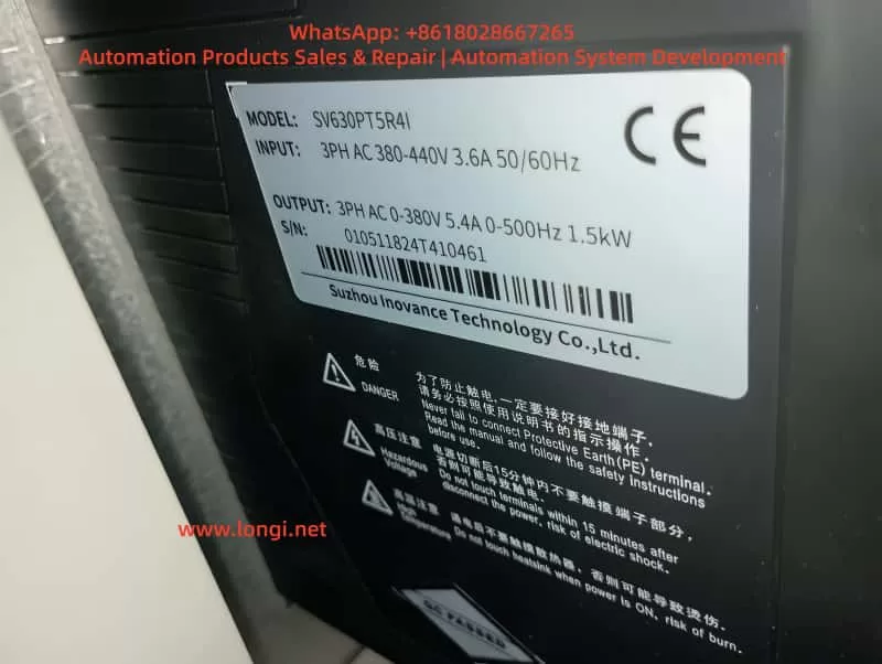
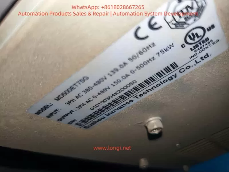
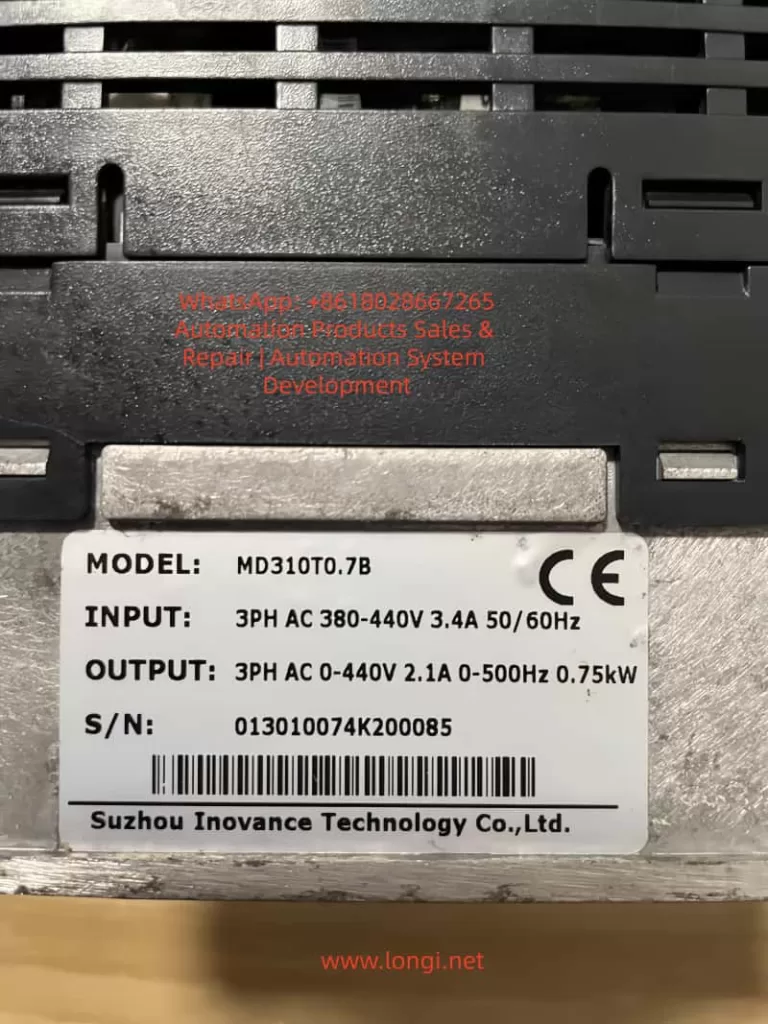
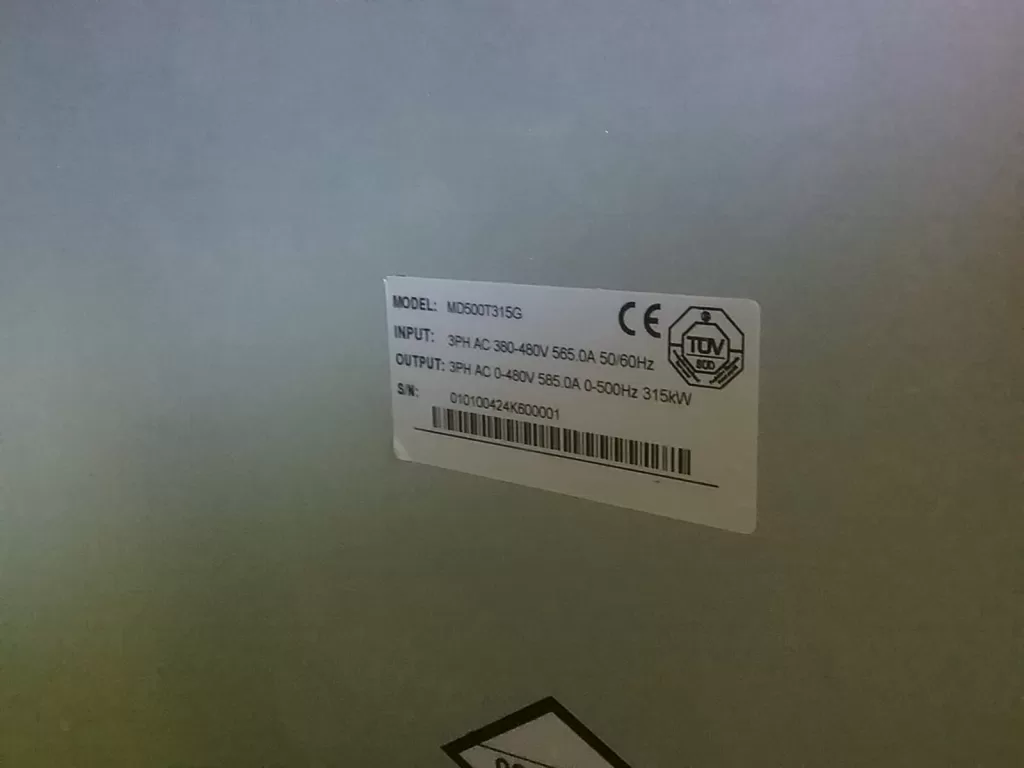
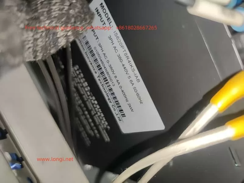
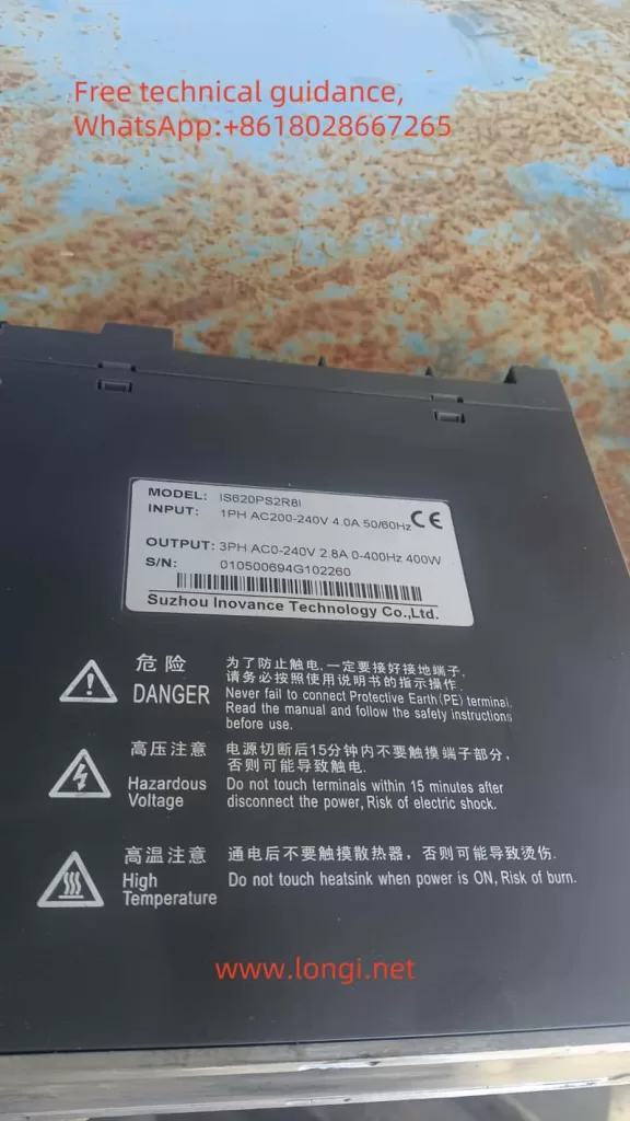
In terms of technical parameters, the MD500T315G model has a three-phase AC input of 380-480V, an output power of 315kW, a current of 585A, and supports a frequency range of 50/60Hz. This series has a built-in PID controller for closed-loop regulation, such as the pressure control of air compressors. The inverter’s fault system is divided into standard faults (Err01-Err79) and user-defined faults (Err80-Err89). The latter allows custom triggering conditions through Digital Inputs (DI), virtual I/O, or expansion cards to achieve specific application protection.

The Electromagnetic Compatibility (EMC) design of the inverter complies with the IEC 61800-3 standard, ensuring anti-interference in industrial environments. The control modes include open-loop and closed-loop, with an overload capacity of 150% rated current for 60 seconds, suitable for the intermittent load of air compressors. Understanding these fundamentals helps analyze Err81: as User-Defined Fault 2, it is usually activated by external logic signals, such as sensor abnormalities or PLC commands.

3. Overview of Air Compressor Systems

Air compressor systems mainly include screw-type, piston-type, and centrifugal-type, among which screw-type compressors most commonly adopt variable frequency control to achieve variable speed operation and energy optimization. System working principle: The motor drives the compressor rotor to compress air to the set pressure, and maintains stability through an unloading valve and a cooling system. After the inverter is involved, the speed can be adjusted according to load requirements, avoiding energy waste from constant-speed operation. Statistics show that variable frequency control can save 20%-40% of electrical energy.

In MD500 applications, the inverter is connected to the motor, pressure sensor, and control PLC. Typical configuration: DI terminals receive pressure switch signals, AI terminals input 4-20mA pressure feedback, and DO terminals output operating status. Most faults of air compressors originate from pressure fluctuations, oil temperature abnormalities, or mechanical wear, which can be mapped to Err81 through user-defined faults. For example, high-pressure protection can be programmed as DI function 45 (User-Defined Fault 2), which is triggered when the pressure exceeds the threshold.

System integration also involves Modbus RTU or Profinet communication to ensure synchronization between the inverter and the upper computer. The dynamic load characteristics of air compressors require the inverter to have fast response, such as the torque boost function (parameter F1-01) of the MD500, which can reach 200% starting torque, suitable for the start-up phase of the compressor.

MD500T315G

4. Introduction to Inovance MD500 Series Inverters

The MD500 series is a high-end general-purpose inverter from Inovance, designed for medium and high-voltage loads, supporting a power range of 0.4kW to 500kW. The MD500T315G model is optimized for heavy-duty applications, with a built-in braking unit and DC reactor to reduce harmonic interference. Key features include:

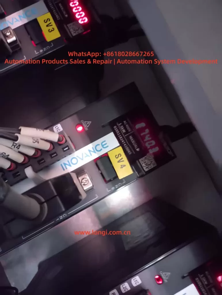
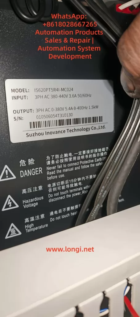
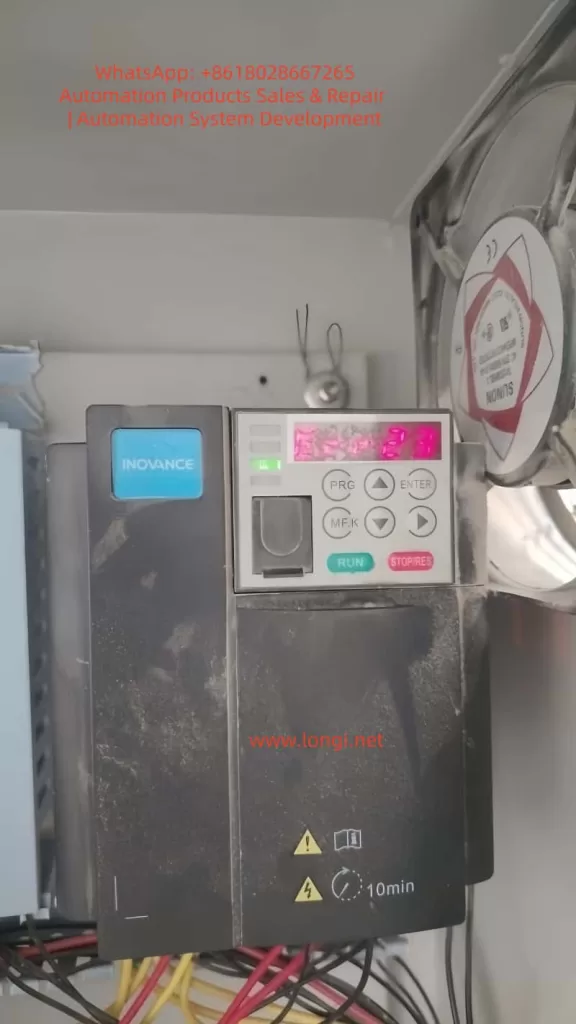
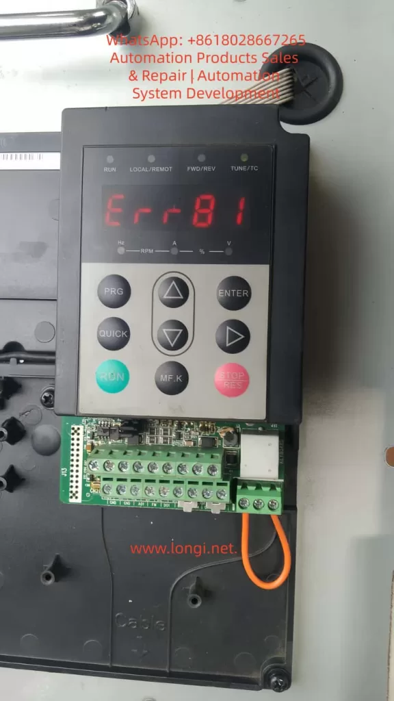
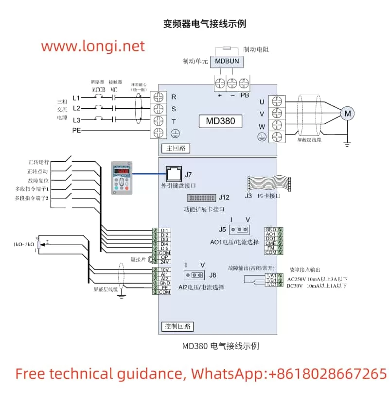
  • Modular Structure: The control board and power board are separated for easy maintenance. Green terminal blocks support quick wiring, such as the control interface shown in the photo.
  • Parameter Grouping: Group F contains basic parameters, and Group A contains advanced extensions. User-defined faults are configured through Group A7, with A7-00 enabling the programmable card.
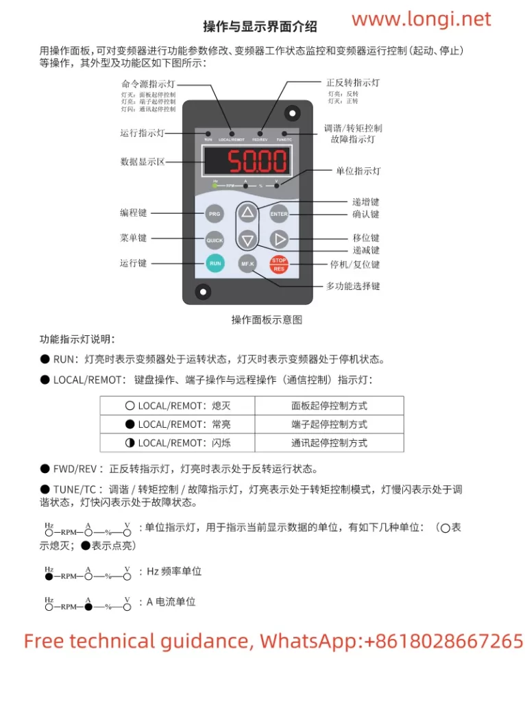
  • Display and Operation: The LED keypad displays frequency, current, and voltage, supporting PRG/ENTER navigation. The QUICK key provides quick access to commonly used parameters.
  • Protection Mechanism: Built-in overcurrent, overvoltage, and undervoltage protection. User-defined faults Err80-Err89 allow expansion of 10 types of protection, with Err81 corresponding to the second user-defined fault.

In air compressors, the MD500 integrates PID regulation (Group F). The pressure setpoint is set through A0-03, and the feedback source is AI1. Communication expansion cards (such as MD38PC1) support custom logic, and Err81 can be triggered by an external PLC to monitor oil level or temperature.

The series manual emphasizes that the diagnosis of user-defined faults such as Err81 requires checking the monitoring parameters in Group U0, such as U0-45 which records the DI status at the time of the fault. This provides a data basis for subsequent analysis.

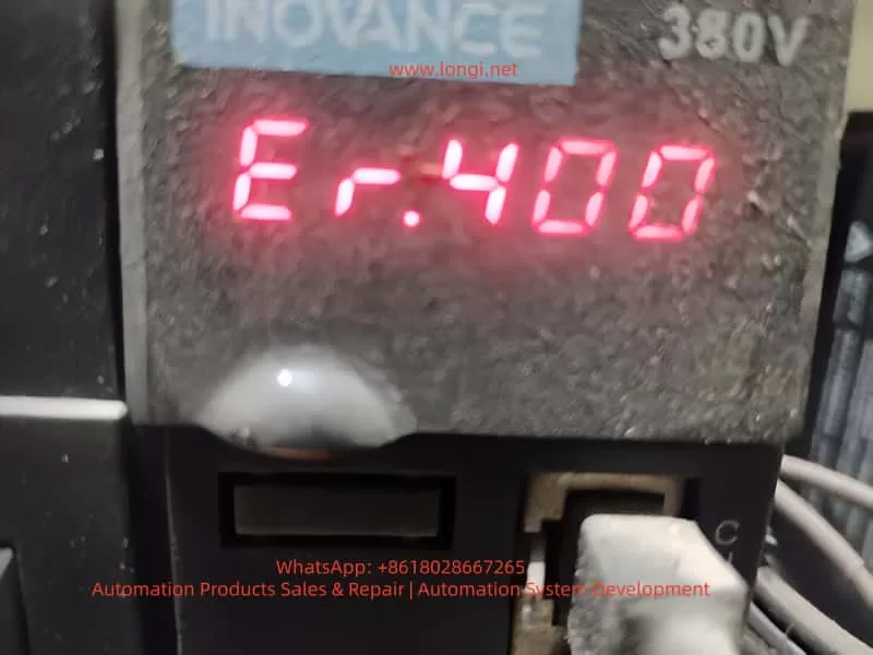
5. Detailed Explanation of Err81 Fault

Err81 is User-Defined Fault 2 of the MD500 series. The code range Err80-Err89 corresponds to user-defined protection mechanisms. According to the manual, Err81 is not a hardware fault but a software-programmable event. It is usually triggered in the following ways:

  • DI Terminal Input: Parameters in Group F4 set DI1-DI10 to function 45 (User-Defined Fault 2). Err81 is triggered when the DI is closed (high level).
  • Virtual I/O: Parameters in Group A1 simulate input signals for scenarios without physical connections.
  • Expansion Card Logic: Parameter A7-09 sets the fault code to 81, which is activated when the program in the card detects an abnormality.
  • Communication Trigger: Write 81 to Modbus address 0x7000 for remote triggering.

Common causes of Err81 in air compressor applications:

  • Sensor Abnormality: Faults in the pressure sensor cause abnormal DI signals. For example, when the pressure exceeds 10bar, the high-pressure switch activates the DI.
  • Load Mismatch: Under the unloading state of the compressor, excessively low speed causes torque abnormalities, triggering custom logic through PID deviation.
  • External Interlock: Safety door opening or emergency stop signals are mapped to Err81 via the PLC.
  • Incorrect Parameter Configuration: A7-09 is mistakenly set to 81, or F4-00 functions are repeatedly defined.

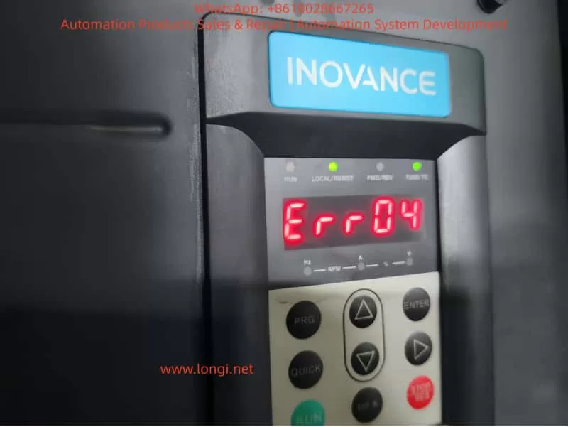
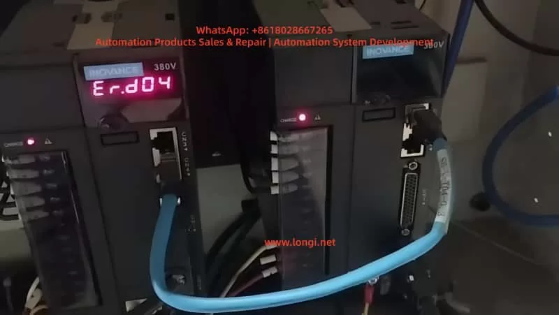
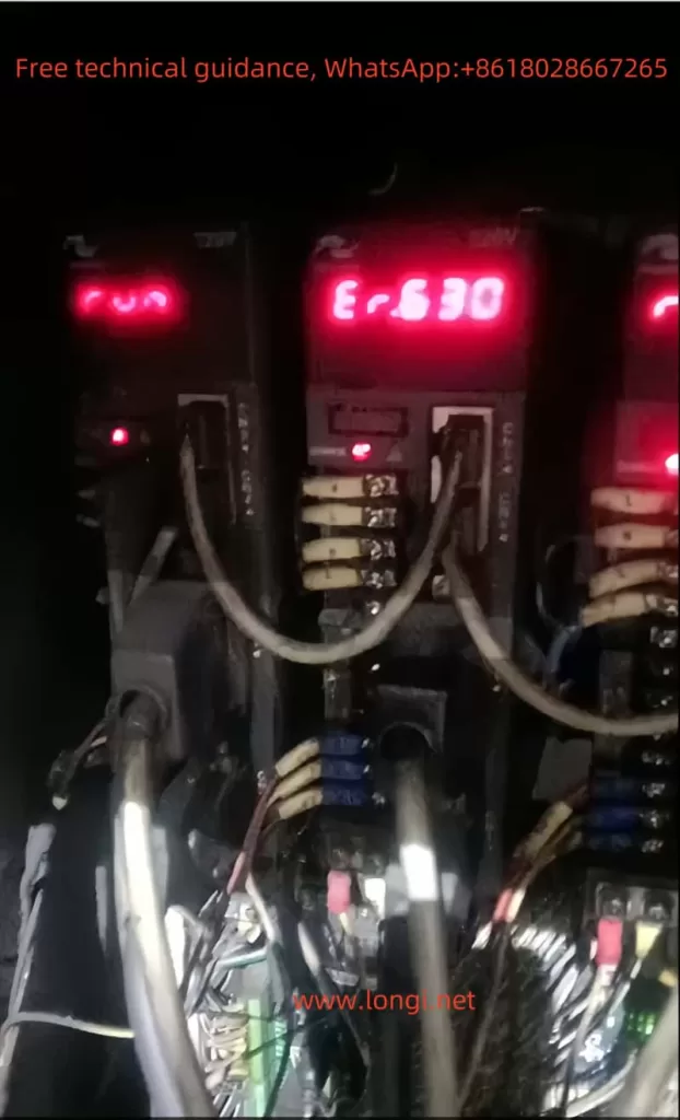
When a fault occurs, the inverter stops output, the relay operates, and the keypad displays “Err81”. The manual indicates that the automatic reset of Err81 is controlled by F9-09, with a default of 0 times and a delay of F9-11 seconds.

Compared to Err80 (User-Defined Fault 1), Err81 allows for more granular protection, such as distinguishing between high-pressure and low-temperature faults. This enhances the safety of air compressors but increases diagnostic complexity.

6. Fault Diagnosis Methods

Diagnosing Err81 requires a systematic approach, combining the manual and tools. The steps are as follows:

  1. Preliminary Observation: Record parameters at the time of the fault. Press PRG to enter U0-62 to confirm code 81, and check U0-45 for current, voltage, and DI status (bit representation, with binary bit 1 indicating activation).
  2. Historical Record Analysis: F9-14 to F9-44 store recent faults, including timestamps (based on the internal clock). Compare the occurrence patterns of multiple Err81 faults to identify periodic issues such as daily peak loads.
  3. Parameter Check: Navigate to Group A7 to verify if A7-00 enables the expansion card; check DI functions in Group F4, and if set to 45, track the external signal source. In air compressors, check if F1-00 PID is enabled and the pressure setting in Group A6.
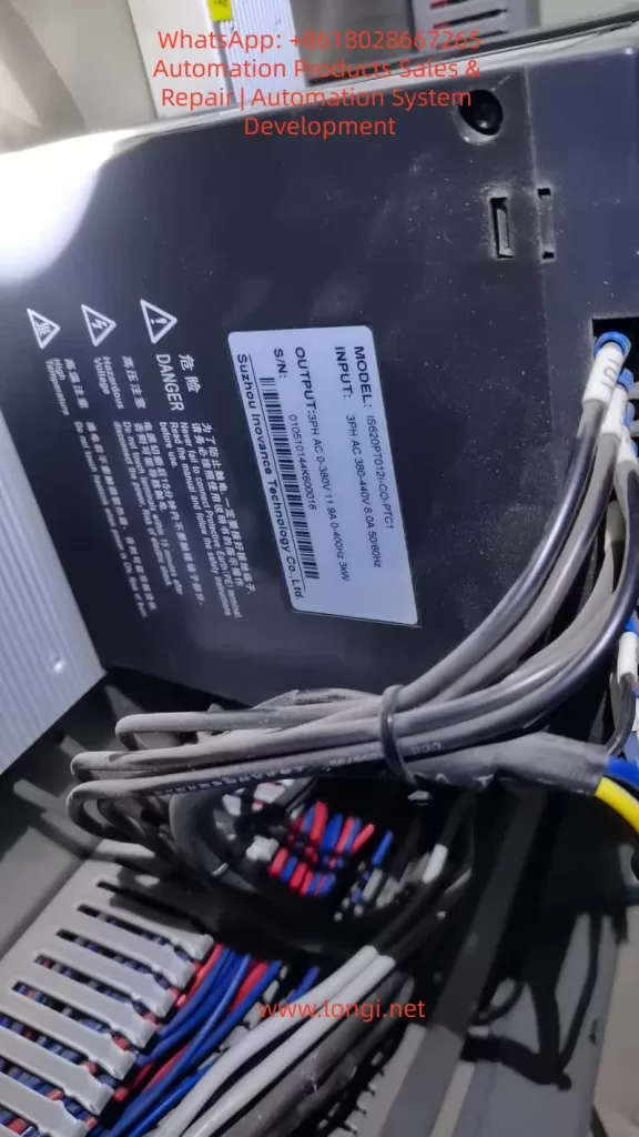
  4. Physical Inspection: After power-off, check the green terminal connections (as shown in the photo with multiple terminals) and measure the DI voltage with a multimeter (typically 24VDC). Inspect the sensor: compare the pressure gauge reading with the AI feedback; a deviation >5% indicates a fault.
  5. Simulation Test: Temporarily disable Err81 (set relevant F4 parameters to 0) and operate the compressor for observation. If normal, the problem lies in the custom logic; if the fault persists, check the motor insulation (megohmmeter >5MΩ).
  6. Advanced Diagnosis: Use Inovance debugging software to connect to the RS485 port and read the complete log. Analyze waveforms: current harmonics >5% indicate power supply issues.

In air compressor scenarios, diagnosis also includes system pressure curves: monitor with a data logger; abnormal speed-pressure relationships indicate the need for PID parameter adjustment (gain F1-02).

7. Fault Troubleshooting Cases

Assume an air compression plant uses the MD500T315G to drive a 315kW screw compressor, experiencing Err81. Diagnostic process:

  • Step 1: U0-45 shows DI3 activation, current is normal.
  • Step 2: Historical records indicate occurrences every morning, coinciding with pressure peaks.
  • Step 3: F4-02=45, DI3 is connected to the high-pressure switch.

Troubleshooting: Replace the switch, clean the filter, and pressure stabilizes. Normal operation resumes after reset.

Another case: Err81 triggered by communication. The PLC writes 81 when monitoring oil temperature >60°C. Troubleshooting: Optimize the cooling fan and adjust the threshold to 65°C.

These cases emphasize that troubleshooting Err81 requires combining mechanical and electrical aspects, with an average repair time of <2 hours.

8. Preventive Measures and Optimization Strategies

The focus of preventing Err81 lies in configuration and maintenance:

  • Parameter Optimization: Set F9-09=3 for automatic reset to reduce downtime. Enable PID parameter auto-tuning (F1-28=1).
  • Regular Maintenance: Check terminal tightness monthly and calibrate sensors. The replacement cycle of air compressor oil filters is <2000 hours.
  • Redundant Design: Add backup DI to avoid single-point failures.
  • Software Upgrade: Update the MD500 firmware to support more custom logic.

Optimization strategies: Integrate IoT modules to monitor DI status in real-time and predict Err81 through cloud platforms. Energy-saving optimization: Dynamically adjust speed with a target COP >6.0.

9. Application of Advanced Technologies

In the future, AI algorithms can analyze Err81 logs to predict faults, such as using machine learning models (SVM classification of DI patterns). Blockchain ensures that parameter configurations are tamper-proof. 5G communication enables remote diagnosis, reducing on-site intervention.

In air compressors, digital twin simulation systems can pre-test the impact of Err81.

10. Conclusion

The diagnosis of the Err81 fault reflects the flexibility of the MD500 inverter, which can be efficiently resolved through systematic methods. In air compressor applications, combining mechanical optimization improves overall performance. Continuous technological iteration will further reduce fault rates and promote industrial intelligence.

Posted on

Analysis and Handling of ER.258 Fault in Inovance IS620P Servo System

In industrial automation, servo systems play a crucial role in precise control and efficient driving tasks. However, in practical applications, servo systems may encounter various faults that affect the stability and efficiency of production lines. One of the common error codes in the Inovance IS620P servo system is ER.258, which can disrupt the normal operation of the system. This article will provide an in-depth analysis of the ER.258 fault, explore its causes, and suggest reasonable handling methods.

ER,258

1. Analysis of ER.258 Fault

1.1 Basic Meaning of ER.258 Fault

The ER.258 fault is typically associated with the speed, torque, and position control in the servo system during the return-to-zero process. According to the design of the Inovance IS620P servo, the return-to-zero process begins after the motor contacts the limit switch. When the motor hits the limit switch, if the motor’s speed and torque meet certain threshold values, the system considers that the motor has reached the limit position and triggers the return-to-zero operation. However, in some cases, if the motor’s speed and torque are out of the normal range, or the system fails to accurately determine if the motor has stopped, the ER.258 fault is triggered.

1.2 Conditions for the Fault to Occur

Specifically, the ER.258 fault is triggered in the following situations:

  • Overcurrent or Overload: When the motor contacts the limit switch, if the current suddenly increases, or if the resistance at the limit position is too high, causing the motor’s torque to exceed the allowed range, an overcurrent or overload protection alarm will be triggered.
  • Exceeding Position Limit: When the motor reaches the mechanical limit, if it continues to try to move or cannot stop properly, the system considers that the motor has exceeded the predefined position and triggers the alarm.
  • Motor Has Not Fully Stopped: When the H05-56 parameter is set too sensitively (such as setting it to 0), the system might wrongly interpret that the motor has stopped while it has not completely stopped, leading to the ER.258 fault.

1.3 Influence of H05-56 Parameter on the Fault

The H05-56 parameter plays an important role during the return-to-zero process. It sets the minimum speed threshold, and when the motor’s speed falls below this value, the system assumes that the motor has stopped and initiates the return-to-zero process. If H05-56 is set to 0, the system becomes overly sensitive in determining if the motor has stopped, which might lead to the motor not fully stopping, but the system falsely interpreting it as a stop and triggering the ER.258 fault.

1.4 Impact of Parameter Setting on the Fault

When the H05-56 parameter is set to 1, the system requires the motor’s speed to drop below 1 rpm before it determines that the motor has stopped and initiates the return-to-zero process. This provides more time and space for the motor to decelerate and avoids triggering the fault caused by speed instability or excessive torque. According to data, changes in the H05-56 parameter directly affect the system’s tolerance, ensuring that the motor and drive system will not cause overcurrent or excessive torque after contacting the limit switch, thus preventing the ER.258 fault.

ISP620P

2. Causes of ER.258 Fault

2.1 Behavior of the Motor After Contacting the Limit Switch

During the return-to-zero process, the servo motor first contacts the mechanical limit switch. At this point, the motor’s torque and speed will be significantly affected. Once the motor contacts the limit switch, the system evaluates the motor’s speed and torque. If the torque exceeds a certain set value, the system assumes that the motor has reached the mechanical limit and stops further movement. If not, the motor may continue to attempt movement, leading to abnormal current or torque, triggering the ER.258 fault.

2.2 Incorrect Determination of Motor Stop Status

When the H05-56 parameter is set to 0, the system may mistakenly determine that the motor has stopped even if it has not completely stopped. This could happen because the motor might still have slight inertia or be moving slightly, causing the system to incorrectly interpret this as a stop condition and initiate the return-to-zero process prematurely, leading to the fault.

2.3 Excessive Current and Torque

After the motor contacts the limit switch, it may experience significant resistance or load, generating excessive torque. If the current exceeds the maximum allowable capacity of the drive, the system will trigger an overcurrent alarm, causing the ER.258 fault to occur.

2.4 Uneven Load or Slow Deceleration

If the motor’s load is uneven or the deceleration process is slow, the motor may continue to attempt movement after contacting the limit switch, generating excessive current or torque, triggering the ER.258 fault. Proper adjustment of the H05-56 parameter can help prevent this situation.

3. Handling Methods for ER.258 Fault

3.1 Adjusting the H05-56 Parameter

As mentioned earlier, the H05-56 parameter has a significant impact on the system during the return-to-zero process. Setting H05-56 to 1 can effectively prevent the ER.258 fault. This setting requires the motor’s speed to drop below 1 rpm before it is considered stopped, thus providing more time for the motor to decelerate and avoiding triggering the fault due to instability.

3.2 Checking Load and Torque

During the return-to-zero process, the motor’s load and torque can cause excessive current, triggering the ER.258 fault. Check whether the motor’s load and torque are too high and ensure that the motor can stop stably after contacting the limit switch. This will help avoid overcurrent or overload protection from being triggered.

3.3 Calibrating the Limit Switch

Check and calibrate the position of the mechanical limit switch to ensure that the motor stops at the correct position. Early or late contact with the limit switch could prevent the motor from stopping properly, leading to excessive torque and current, and triggering the ER.258 fault.

3.4 Adjusting the Motor’s Deceleration Settings

If the motor’s deceleration process is too slow, it may cause excessive torque or current, triggering the fault. Adjust the motor’s deceleration time and method to ensure that the motor decelerates smoothly after contacting the limit switch, avoiding excessive current and torque.

3.5 Regular Maintenance and Inspection

Regularly inspect the operation status of the servo system, including the motor, drive, limit switches, and other components. Clean the mechanical parts from dirt and check the motor’s operating condition to ensure that the system operates within normal ranges and prevent faults due to wear or malfunction.

4. Conclusion

The ER.258 fault is a common alarm in the Inovance IS620P servo system during the return-to-zero process. It is usually related to motor speed, torque, position control, and the functioning of the limit switch. By adjusting the H05-56 parameter, checking the load and torque, calibrating the limit switch, optimizing the motor deceleration settings, and performing regular maintenance, the occurrence of the ER.258 fault can be effectively prevented. Proper system settings and regular maintenance ensure the stable operation of the servo system, improving the reliability and efficiency of the equipment.

Posted on

Instruction Guide and Fault Handling for IS620P Series Servo System by Inovance

Inovance IS620P Series Servo System Instruction Guide

1. Setting Up Speed Mode with External Terminal Start and Potentiometer Speed Regulation

Parameter Settings

To configure the Inovance IS620P series servo system for speed mode control with external terminal start and potentiometer speed regulation, the following parameters need to be set:

  • H02-00: Set to 0 to select speed control mode.
  • H06-00: Set to 1 to select AI1 as the speed command source. If AI2 is used, set to 2.
  • H06-02: Set to 0 to select the main speed command A as the speed source.
  • H03-50 to H03-59: Configure the offset, gain, and other parameters of the AI1 channel according to the potentiometer’s voltage range to ensure a linear relationship between the potentiometer’s output voltage and the speed command.
  • H06-05 and H06-06: Set the acceleration and deceleration times for the speed command to ensure smooth start and stop.

Terminal Connections

  • AI1 Terminal: Connect the output of the potentiometer to receive the speed regulation signal.
  • DI1 Terminal: Set to servo enable (FunIN.1: S-ON) and connect to an external start signal.
  • Other DI Terminals: Configure other functions as needed, such as direction control and external reset.

2. Jog Operation

Parameter Settings

  • H06-04: Set the jog speed, typically in rpm.
  • H0D-11: Jog test run function entry code, which allows jog test runs to be performed through the panel settings.

Operation Steps

  1. Access the parameter settings interface through the panel.
  2. Set H06-04 to the desired jog speed.
  3. Use the jog buttons on the panel or activate jog operation through external DI terminals (such as FunIN.18 and FunIN.19).
  4. Control the direction and stopping of the jog operation through the panel or external signals.

3. CANOPEN Communication Setup

Hardware Connection

  • Connect the CAN interface of the servo drive to the CAN interface of the upper computer using shielded twisted pair cables.
  • Ensure that the shielding layer of the connecting cable is properly grounded to reduce interference.

Parameter Settings

  • H0C-00: Set the servo axis address to ensure each drive has a unique address.
  • H0C-08: Set the CAN communication rate to match the upper computer.
  • H0C-09: Enable communication VDI.
  • H17 Group Parameters: Configure virtual DI and DO functions as needed.
er.630 fault

Fault Code Meanings and Handling Methods for Inovance Servo IS620P Series

Fault Code er.630

Meaning

The er.630 fault code indicates motor stall overtemperature protection. When the motor stalls due to excessive load or mechanical obstruction during operation, and the motor temperature rises to a certain level, the servo drive will report this fault.

Solution

  1. Check Mechanical Load: Confirm whether there is any obstruction or excessive load in the mechanical part and address it promptly.
  2. Adjust Gain Parameters: Adjust the speed loop and position loop gain parameters according to the mechanical load to prevent the motor from stalling due to excessive gain.
  3. Increase Acceleration and Deceleration Time: Increase the settings of H06-05 and H06-06 to make the motor start and stop more smoothly, reducing the possibility of stalling.
  4. Check Motor and Drive Connections: Ensure that the connections between the motor and the drive are correct to avoid stalling caused by wiring errors.
  5. Monitor Motor and Drive Status: Use the Inovance drive debugging platform to monitor the motor’s operating status and the drive’s output commands to identify any anomalies.
IS620P Huichuan servo physical picture

If the above methods fail to resolve the issue, it may be necessary to replace the servo drive or motor with a higher capacity to accommodate the current load demand. Additionally, when handling faults, ensure safe operation to prevent personnel injury or equipment damage.

By following the above setup and fault handling methods, users can effectively use and maintain the Inovance IS620P series servo system, ensuring its stable and efficient operation.

Posted on

User Manual Guide for Inovance Inverter MD380 Series

I. Introduction to the Operation Panel Functions and Parameter Settings

1.1 Operation Panel Functions

The operation panel of the Inovance MD380 series inverter is a crucial tool for users to set parameters, monitor status, and diagnose faults. The operation panel primarily consists of an LED display, function keys, and multiple input/output ports. The LED display shows current operating parameters such as frequency, voltage, and current. The function keys include PRG (Program), ENTER (Confirm), RUN (Run), STOP/RESET (Stop/Reset), and MF.K (Multi-Function Key), which users utilize for menu navigation and parameter modification.

1.2 Restoring Factory Defaults

Restoring factory defaults clears user-defined parameters, resetting the inverter to its default settings at the time of manufacture. The steps are as follows:

  1. Enter the Function Parameter Mode: Press the PRG key to enter the function parameter mode.
  2. Select the FP Group Function Code: Use the ▲ or ▼ keys to select the FP group function code (FP-01).
  3. Set to Restore Factory Defaults: Press the ENTER key to enter the FP-01 parameter setting, set the value of FP-01 to 1, and then press ENTER to confirm. The inverter will then automatically restart and restore to its factory default settings.

1.3 Setting and Clearing Passwords

Password protection prevents unauthorized users from modifying inverter parameters. The steps to set and clear passwords are as follows:

  1. Setting a Password: Set the value of the FP-00 function code to a non-zero number, such as 1234, and then press ENTER to confirm. Password protection is now enabled, and entering the function parameter mode will require a password.
  2. Clearing the Password: Set the value of the FP-00 function code to 0 and then press ENTER to confirm. This disables password protection, and entering the function parameter mode will no longer require a password.
Function Description Diagram of Huichuan MD380 Series Inverter Operation Panel

II. Terminal Start/Stop and External Potentiometer Speed Adjustment Settings

2.1 Wiring Instructions

To achieve terminal start/stop and external potentiometer speed adjustment, the control terminals of the inverter must be correctly connected. The specific wiring is as follows:

  • Start Terminal (DI1): Connect one end of the external start button to DI1 and the other end to the common terminal (COM).
  • Stop Terminal (DI2): Connect one end of the external stop button to DI2 and the other end to the common terminal (COM).
  • Speed Adjustment Terminal (AI1): Connect the center tap of the external potentiometer to AI1, and the two ends of the potentiometer to +10V and GND, respectively.

2.2 Parameter Settings

After completing the wiring, the inverter must be configured with specific parameters to achieve the desired functionality. The settings are as follows:

  1. Set the Command Source: Set the value of the F0-02 function code to 1 to select the terminal command channel.
  2. Set DI1 and DI2 Functions: Set the value of the F4-00 function code to 1 (forward operation) and the value of the F4-01 function code to 4 (reverse operation) or as required.
  3. Set AI1 Function: Configure the F4-13 to F4-16 function codes to set the input range and corresponding set values for AI1, ensuring that the output of the external potentiometer matches the frequency setting of the inverter.
  4. Other Related Settings: Set parameters such as acceleration and deceleration times and frequency limits as needed.
Basic wiring diagram of Huichuan MD380 series frequency converter

III. Fault Codes and Troubleshooting

3.1 Fault Codes and Their Meanings

The Inovance MD380 series inverter features comprehensive fault self-diagnosis functionality. When a fault occurs, the inverter displays the corresponding fault code. Common fault codes and their meanings are as follows:

  • Err01: Overcurrent fault, indicating that the inverter output current exceeds the set value.
  • Err02: Overvoltage fault, indicating that the inverter input voltage is too high.
  • Err03: Undervoltage fault, indicating that the inverter input voltage is too low.
  • Err07: Overload fault, indicating that the inverter output torque exceeds the set value.
  • Err11: Motor overload fault, indicating that the motor current is too high.
  • Err12: Input phase loss fault, indicating that the inverter input power supply is missing a phase.
  • Err15: External fault, indicating that the external fault input terminal is active.
  • Err16: Communication abnormality fault, indicating that communication between the inverter and the host computer is abnormal.

3.2 Troubleshooting

Different fault codes require specific troubleshooting steps:

  • Overcurrent Fault (Err01): Check if the motor and load are too large, and adjust the acceleration and deceleration times or reduce the output frequency.
  • Overvoltage Fault (Err02): Check if the input power supply voltage is too high or install a braking resistor to dissipate excess energy.
  • Undervoltage Fault (Err03): Check if the input power supply voltage is too low or if the power supply line connection is poor.
  • Overload Fault (Err07): Check if the load is too large and adjust the overload protection parameters.
  • Motor Overload Fault (Err11): Check if the motor is stalled or the load is too large, and adjust the motor overload protection parameters.
  • Input Phase Loss Fault (Err12): Check if the input power supply is missing a phase or if the power supply line connection is good.
  • External Fault (Err15): Check if the external fault input terminal is misconnected or damaged and eliminate the external fault source.
  • Communication Abnormality Fault (Err16): Check if the communication line is connected correctly or replace the communication cable.

By following the steps outlined above, users can gain a comprehensive understanding of the operation panel functions, parameter setting methods, terminal start/stop and external potentiometer speed adjustment settings, as well as fault code troubleshooting for the Inovance MD380 series inverter, thereby enabling better use and maintenance of the inverter equipment.

Posted on

User Manual Guide for Inovance CS700 Series Crane-specific Inverter

I. Operation Panel Function Description and Basic Operations

Operation Panel Functionality

The Inovance CS700 series crane-specific inverter is equipped with an intuitive and user-friendly operation panel, which primarily includes the following buttons and indicators:

  • Buttons: Including PRG (programming key), ENTER (confirmation key), increment key (▲), decrement key (▼), shift key (◀/▶), RUN (run key), STOP/RES (stop/reset key), MF.K (multi-function key), QUICK (menu key), etc.
  • Indicators: Including RUN (run indicator), LOCAL/REMOT (command source indicator), FWD/REV (forward/reverse indicator), TUNE/TC (tuning/torque control/fault indicator), etc.

Basic Operations

Function diagram of Huichuan CS700 crane dedicated VFD operation panel
  1. Start and Stop:
    • Press the RUN button to start the inverter, and the inverter run indicator (RUN) will light up.
    • Press the STOP/RES button to stop the inverter, and the inverter run indicator will go out.
  2. Speed Regulation:
    • Enter the programming mode by pressing the PRG button, adjust the target frequency using the increment key (▲) and decrement key (▼), and then press the ENTER button to confirm.

Password Setting and Removal

  • Password Setting: Set the password for all function parameters through parameter AF.00, the password for the second-level menu through parameter bF.00, and the password for the third-level menu through parameter FF.00.
  • Password Removal: Set the password parameter to 0 to remove the password protection.

Parameter Initialization

  • Press the PRG button to enter the programming mode, select parameter AF.01 (restore factory parameters for the first-level menu), bF.01 (restore factory parameters for the second-level menu), or FF.10 (restore factory parameters for the third-level menu), and press the ENTER button to confirm.
Typical wiring diagram of Huichuan CS700 crane specific VFD

II. Crane Mode and PG Encoder Feedback Settings

Crane Mode Selection

The CS700 series inverter supports multiple crane modes, generally achieved through the multi-speed function. The specific setting steps are as follows:

  1. Enter the programming mode, select parameter A0.07, and set it to 0 to choose multi-speed as the frequency source.
  2. Set parameters b3.01~b3.05 to define DI1~DI5 as multi-speed selections 1~5, respectively.
  3. Set the corresponding frequency for each speed in parameters b5.00~b5.07.

PG Encoder Feedback Settings

If PG encoder feedback is selected, the following settings and wiring are required:

  1. Parameter Settings:
    • Enter the programming mode, select parameter b1.00, and set it to 1 to choose encoder vector control (closed-loop control mode).
    • Set parameters b2.00 (encoder lines) and b2.01 (encoder type) according to the actual encoder type used.
  2. Wiring:
    • Connect the encoder signal wires to the PG card interface of the inverter, with specific wiring reference to the wiring diagram in the manual.

III. Fault Code Meanings and Solutions

The CS700 series inverter provides a wealth of fault codes to help users quickly locate and resolve issues. Below are some common fault codes, their meanings, and solutions:

  1. Er02: Acceleration Overcurrent
    • Meaning: Grounding or short circuit in the inverter output circuit, or too short acceleration time, etc.
    • Solution: Check the peripheral circuit and eliminate grounding or short circuit faults; increase the acceleration time.
  2. Er03: Deceleration Overcurrent
    • Meaning: Grounding or short circuit in the inverter output circuit, or too short deceleration time, etc.
    • Solution: Check the peripheral circuit and eliminate grounding or short circuit faults; increase the deceleration time.
  3. Er04: Constant Speed Overcurrent
    • Meaning: Grounding or short circuit in the inverter output circuit, or low voltage, etc.
    • Solution: Check the peripheral circuit and eliminate grounding or short circuit faults; adjust the voltage to the normal range.
  4. Er05: Acceleration Overvoltage
    • Meaning: High input voltage, or external force dragging the motor during acceleration, etc.
    • Solution: Adjust the voltage to the normal range; eliminate external force dragging or install braking resistors.
  5. Er08: Control Power Supply Fault
    • Meaning: Input voltage is not within the specified range.
    • Solution: Adjust the voltage to meet the specified requirements.
  6. Er10: Inverter Overload
    • Meaning: Excessive load or motor stall, or undersized inverter selection, etc.
    • Solution: Reduce the load and check the motor and machinery; select an inverter with a larger power rating.
  7. Er11: Motor Overload
    • Meaning: Improper setting of motor protection parameters, or excessive load, etc.
    • Solution: Set the motor protection parameters correctly; reduce the load.
  8. Er12: Input Phase Loss
    • Meaning: Abnormal three-phase input power.
    • Solution: Check and eliminate issues in the peripheral circuitry.
  9. Er14: Module Overheat
    • Meaning: High ambient temperature or blocked air duct, etc.
    • Solution: Lower the ambient temperature and clean the air duct.
  10. Er37: Frequency Direction Anomaly
    • Meaning: The direction of the given running frequency is opposite to that of the motor feedback frequency.
    • Solution: Check the motor parameter settings and adjust parameter bC.02 if necessary.
  11. Er41: Loose Brake Fault
    • Meaning: Error in the input of the loose brake feedback signal.
    • Solution: Check the brake circuit wiring and the function selection of the control panel’s loose brake feedback input point.
  12. Er42: Holding Brake Fault
    • Meaning: Error in the input of the holding brake feedback signal.
    • Solution: Check the brake circuit wiring and the function selection of the control panel’s holding brake feedback input point.

IV. Conclusion

The Inovance CS700 series crane-specific inverter is a powerful and easy-to-operate inverter dedicated to crane equipment. Through this guide, users can quickly master the basic functions of the operation panel, the setting method for crane modes, the configuration steps for PG encoder feedback, and solutions to common fault codes. It is hoped that this user guide will help users better use and maintain the CS700 series inverters, improving the work efficiency and safety of crane equipment.