Posted on Leave a comment

User Manual Operation Guide for Inovance GD270 Series Inverter

I. Introduction to Inverter Operation Panel Functions and Parameter Initialization

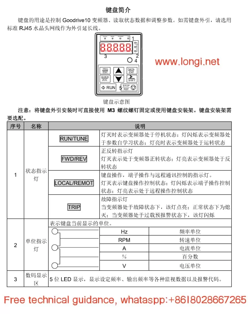
The Inovance GD270 series inverter is an efficient drive specifically designed for fan and pump applications. Its operation panel features a rich set of functions, facilitating user operation and monitoring. The operation panel mainly includes an LED keyboard for displaying the inverter’s operating status, set frequency, and other parameters, as well as for parameter settings and operational control.
Front image of GD270

Parameter Initialization:

  1. Press the PRG/ESC button to enter the parameter setting group.
  2. Use the up and down buttons to select the parameter group or parameter that needs to be initialized.
  3. Press the DATA/ENT button to enter the next level menu for specific parameter settings.
  4. Set the parameters that need to be initialized to their factory defaults or desired values.
  5. After completing the settings, press the PRG/ESC button to return to the initial interface and save the settings.

Setting Password and Parameter Access Restrictions:

  1. Press the PRG/ESC button to enter the parameter setting group, and use the up and down buttons to navigate to the P07 Human-Machine Interface group.
  2. Press the DATA/ENT button to enter the next level menu, and use the up and down buttons to navigate to P07.00 User Password (if it’s already set, it doesn’t need adjustment).
  3. Press the DATA/ENT button to enter the parameter, and use the SHIFT button to shift and set the password (e.g., 02021). Press DATA/ENT to confirm.
  4. Press the PRG/ESC button twice to return to the initial interface, and wait for 1 minute for the password to take effect.
  5. Afterward, when pressing the PRG/ESC button to enter the parameter settings again, the user will need to input the previously set password.
  6. To cancel the password, follow the same steps to enter the P07.00 parameter, set the password to 0, and press DATA/ENT.
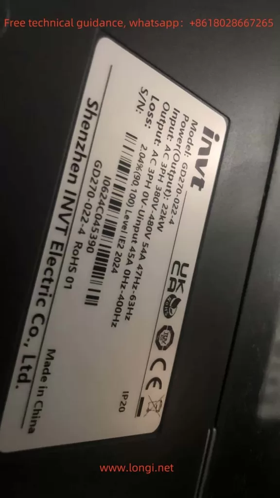
Side view of GD270

Using Fire Crossing Control Function:

The GD270 series inverter supports a fire crossing control function, which can ensure that the inverter continues to operate for a period of time in case of a fire or other emergencies, allowing for safe shutdown or other emergency measures. The specific setup method requires referring to the inverter’s advanced function settings manual and configuring according to actual conditions.

II. Terminal Forward/Reverse Control and External Potentiometer Frequency Speed Regulation

Terminal Forward/Reverse Control:

  1. Wiring: Connect the multi-function input terminals (such as forward and reverse terminals) to the control signal source (such as buttons, relay outputs, etc.).
  2. Parameter Settings:
    • Enter the parameter setting group and select the control command channel (such as P00.00), setting it to the terminal command channel.
    • Set the corresponding function codes for forward and reverse (such as P00.01, P00.02), corresponding to the forward and reverse terminals, respectively.

External Potentiometer Frequency Speed Regulation:

  1. Wiring: Connect the output terminal (V terminal) of the potentiometer to the analog voltage input terminal of the inverter (such as AI1), and connect the common terminal (GND terminal) of the potentiometer to the common ground terminal of the inverter.
  2. Parameter Settings:
    • Enter the parameter setting group and select the frequency setting selection (such as P01.00), setting it to external terminal given.
    • Set the parameters corresponding to the analog voltage input (such as P01.01), selecting the AI1 terminal.
    • Adjust other relevant parameters as needed, such as the analog voltage input range and frequency upper limit.
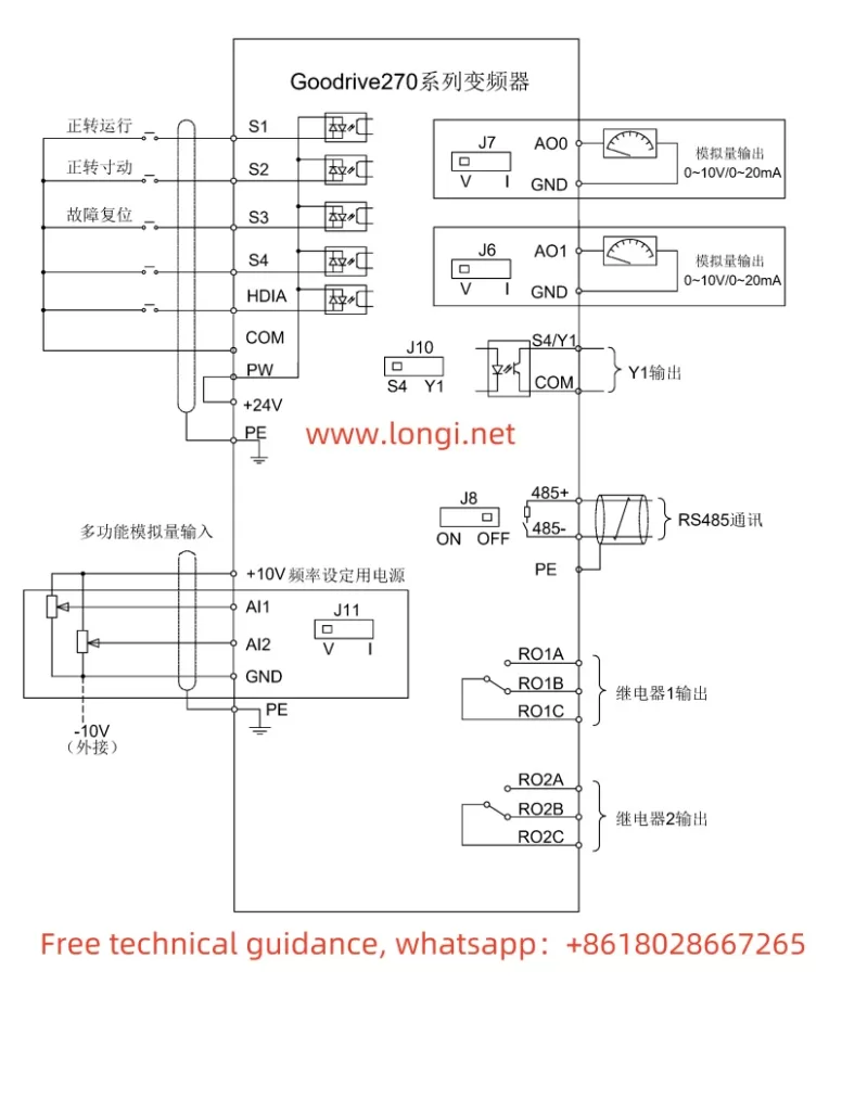
GD270标准配线图

III. Fault Codes and Handling Methods

The GD270 series inverter’s fault code system is quite comprehensive, covering numerous potential issues. The following lists some common fault codes, their meanings, and handling methods:

  1. OL (Overload): Indicates that the inverter’s output current exceeds the rated current. Handling methods include checking if the load is too heavy, if the motor is jammed, if the parameter settings are reasonable, etc.
  2. E7 (Encoder Signal Loss): Indicates that the inverter has not received an encoder signal. Handling methods include checking if the encoder connection is good, if the encoder is damaged, etc.
  3. E8 (Fan Fault): Indicates that the inverter’s internal fan has failed. Handling methods include checking if the fan is operating normally, if the fan connection is good, etc.
  4. OC (Overcurrent): Indicates that the inverter’s output current exceeds the allowable value. Handling methods include checking if the load is too heavy, if the motor is jammed, if the power supply voltage is too high or too low, etc.

For other fault codes not explicitly stated, such as 5P1, further technical support or detailed user manuals may be required for interpretation. When handling faults, it is essential to understand the inverter’s various parameter settings and operating status to accurately diagnose the fault cause and take appropriate measures.

IV. Conclusion

The Inovance GD270 series inverter is a powerful and easy-to-operate product. Through this guide, users can better understand the inverter’s operation panel functions, parameter setting methods, terminal wiring and parameter configuration, as well as fault code handling and other aspects. In practical applications, users should choose appropriate control methods, parameter settings, and fault handling methods based on specific conditions to ensure the inverter’s normal operation and efficient energy saving. At the same time, it is recommended that users regularly consult the inverter’s user manual and related technical documents to obtain the latest product information and technical support.

Posted on Leave a comment

User Manual Guide for INVT INVERTER Goodrive 10 (GD10) Series

I. Function Introduction of VFD Operation Panel (Keyboard)

The operation panel (keyboard) of the INVT Goodrive 10 series INVERTER serves as the primary interface for user interaction. This keyboard is highly functional, capable of performing basic operations, status monitoring, and parameter settings on the INVERTER. Here are some key functions:

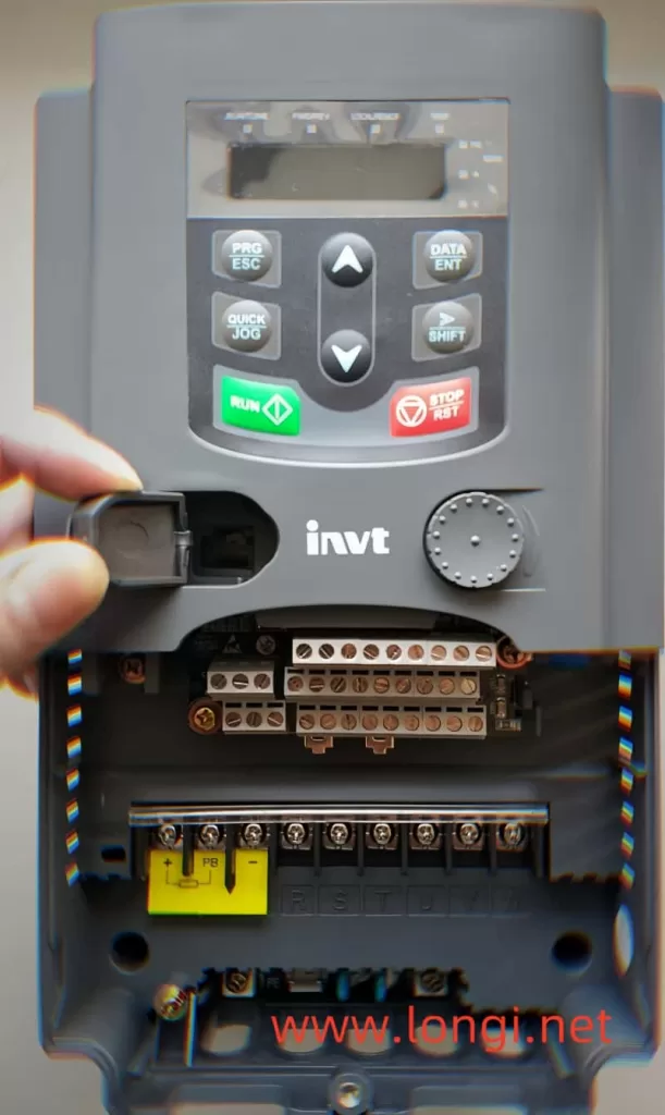
Function diagram of the operation panel of the NVIDIA GD10 Inverter
  1. Status Indicators:
    • RUN/TUNE: Indicates whether the INVERTER is running.
    • FWD/REV: Indicates the forward or reverse rotation status of the motor.
    • LOCAL/REMOT: Indicates the current control mode (local keyboard control or remote communication control).
    • TRIP: Indicates whether the INVERTER is in a fault state.
  2. Digital Display Area: A 5-digit LED display for showing set frequencies, output frequencies, currents, voltages, and various monitoring data and alarm codes.
  3. Operation Buttons:
    • PRG/ESC: Programming key for entering or exiting the parameter setting menu.
    • DATA/ENT: Confirmation key for validating parameter settings or entering the next menu level.
    • UP/DOWN: Increment/decrement keys for adjusting parameter values.
    • SHIFT: Right shift key for selecting different modification bits during parameter setting.
    • RUN/STOP/RST: Run/Stop/Reset keys for controlling the start, stop, and fault reset of the INVERTER.
    • QUICK/JOG: Quick multifunction key, whose function is set by parameter P07.02 and can include jogging, display state switching, etc.
Control Circuit and Terminal Wiring Diagram of AD10 Inverter from Envision

II. Methods for Setting and Deleting Passwords on the INVERTER

  1. Setting a Password:
    • Enter the parameter setting menu (press PRG/ESC). Locate parameter P07.00 and set it to a non-zero value, which will serve as the user password. After exiting the parameter setting menu, password protection will be activated.
  2. Deleting a Password:
    • Set parameter P07.00 to 0 to disable password protection. Note that password deletion must be performed without password protection in place.

III. Steps to Restore the INVERTER to Factory Defaults

To restore the INVERTER to its factory settings, follow these steps:

  1. Enter the parameter setting menu (press PRG/ESC).
  2. Locate parameter P00.18 and set it to 1 (restore default values). The INVERTER will begin restoring default parameters, which may take a few seconds.
  3. After restoration, parameter P00.18 automatically reverts to 0. At this point, the INVERTER has been restored to its factory settings.

IV. Specific Steps for Terminal Start/Stop and External Potentiometer Speed Adjustment

Wiring Steps:

  1. Start/Stop Terminal Wiring:
    • Connect the start signal from the external control circuit to the S1 terminal of the INVERTER and the stop signal to the S2 terminal.
    • Ensure that the control circuit power matches the INVERTER’s control power.
  2. External Potentiometer Wiring:
    • Connect the output end of the potentiometer to the AI1 terminal (analog input terminal) of the INVERTER.
    • Connect the power end of the potentiometer to an appropriate power source, typically a 10V DC power supply.

Parameter Setting Steps:

  1. Set the Run Command Channel:
    • Enter the parameter setting menu and locate parameter P00.01. Set it to 1 (terminal run command channel).
  2. Set the Analog Input Function:
    • Locate parameter P00.06 and set it to 1 (keyboard analog AI1 setting). This way, the frequency of the INVERTER will be determined by the analog input from the AI1 terminal.
  3. Adjust Other Related Parameters (if necessary):
    • Adjust acceleration time, deceleration time, maximum output frequency, and other parameters based on actual application requirements to achieve optimal control performance.

V. Analysis and Solution of INVERTER Fault Codes

The Goodrive 10 series INVERTER features comprehensive fault protection functions, capable of monitoring the INVERTER’s operating status in real-time and providing fault codes when issues arise. Here are some common fault codes and their solutions:

  1. OV1 (Acceleration Overvoltage):
    • Possible Causes: Excessively high input voltage; too short deceleration time.
    • Solutions: Check if the input voltage is normal; increase the deceleration time as needed.
  2. OC1 (Acceleration Overcurrent):
    • Possible Causes: Excessive load; low grid voltage.
    • Solutions: Check if the load exceeds the INVERTER’s rated load; check if the grid voltage is normal.
  3. UV (Bus Undervoltage Fault):
    • Possible Causes: Low grid voltage; input power phase loss.
    • Solutions: Check if the grid voltage is normal; check for input power phase loss.
  4. OH2 (Inverter Module Overheat Fault):
    • Possible Causes: High ambient temperature; poor heat dissipation.
    • Solutions: Improve the INVERTER’s heat dissipation conditions; reduce the ambient temperature.

When the INVERTER encounters a fault, users should first refer to the fault code to identify possible causes and apply the corresponding solutions. If the problem persists, contact INVT’s technical support for assistance.

VI. Conclusion

The user manual for the INVT Goodrive 10 series INVERTER serves as an essential reference for users to operate and maintain the INVERTER. This document provides detailed information on the INVERTER’s operation panel functions, password setting and deletion, steps to restore factory defaults, specific procedures for terminal start/stop and external potentiometer speed adjustment, as well as fault code analysis and solutions. We hope this content will help users better utilize and maintain the Goodrive 10 series INVERTER.

Posted on Leave a comment

User Manual for Invt GD300-01A-RT Series VFD Dedicated for Air Compressors – Usage Guide

This guide aims to assist users in better understanding and utilizing the Invt GD300-01A-RT Series VFD, a single frequency converter specifically designed for air compressor control, featuring efficiency, ease of use, and reliability. Below is a detailed usage guide.

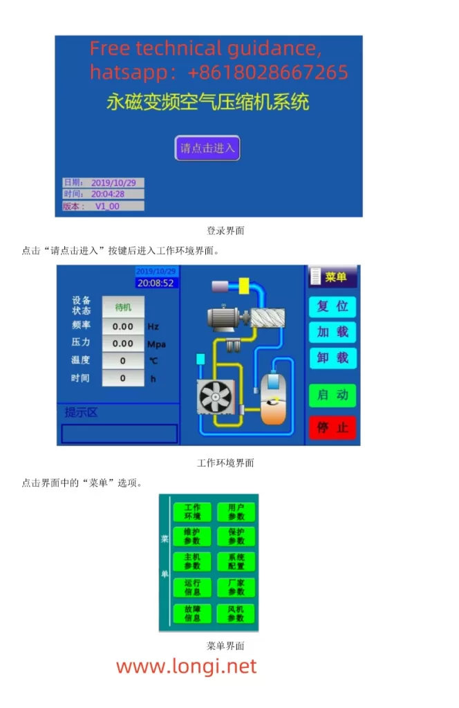
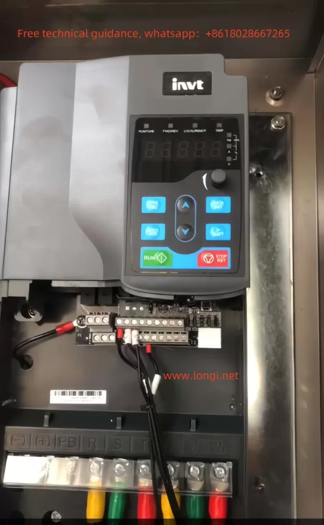
GD300-01A-RT menu interface diagram

I. Operating Methods for Controlling Air Compressors

  1. Wiring Method
    Main Circuit Wiring:
    Connect the power input terminals (R, S, T or L1, L2, L3) to the electrical grid.
    Connect the motor output terminals (U, V, W) to the main motor of the air compressor.
    The grounding terminal PE must be grounded with a grounding resistance of less than 10Ω.
    Control Circuit Wiring:
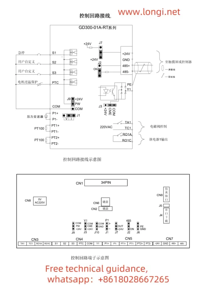
    Connect signal lines, such as pressure sensors and temperature sensors, to the corresponding input terminals (e.g., P1+, P1-) as per actual requirements.
    Connect external control signals (e.g., start, stop, load, unload) to the respective input terminals (e.g., S1, S2, S3).
    If needed, connect fault outputs, alarm outputs, etc., to external devices.
  2. Parameter Settings
    Motor Parameter Settings:
    Enter the “Main Unit Parameter Settings” interface and set parameters such as motor type, rated power, rated frequency, rated voltage, and rated current based on the actual motor nameplate parameters.
    Perform motor parameter self-learning to ensure the VFD can accurately control the motor.
    Air Compressor-Specific Parameter Settings:
    Set the range and calibration points for pressure sensors and temperature sensors.
    Set parameters such as loading pressure, unloading pressure, no-load operating frequency, and minimum loading operating frequency to suit the operational needs of the air compressor.
    Set parameters such as fan control mode and maintenance timeout as required.

II. Using External Terminals for Starting and External Potentiometer for Frequency Adjustment

  1. Wiring Method
    External Start Terminal Wiring:
    Connect the external start signal (e.g., push-button switch) to the S1 terminal (forward start) and the COM terminal.
    For reverse start, connect the signal to the S2 terminal.
    External Potentiometer Wiring:
    Connect the center tap of the external potentiometer to the AI1 terminal (analog input 1).
    Connect the other two terminals of the potentiometer to +10V and GND terminals to provide the required power supply voltage for the potentiometer.
  2. Parameter Settings
    Operation Command Channel Settings:
    Enter the “Basic Function Group” parameter settings and set P00.01 to 1 (terminal operation command channel).
    Frequency Command Selection:
    Set P00.06 to 1 (analog P1-setting) to enable external potentiometer frequency adjustment.
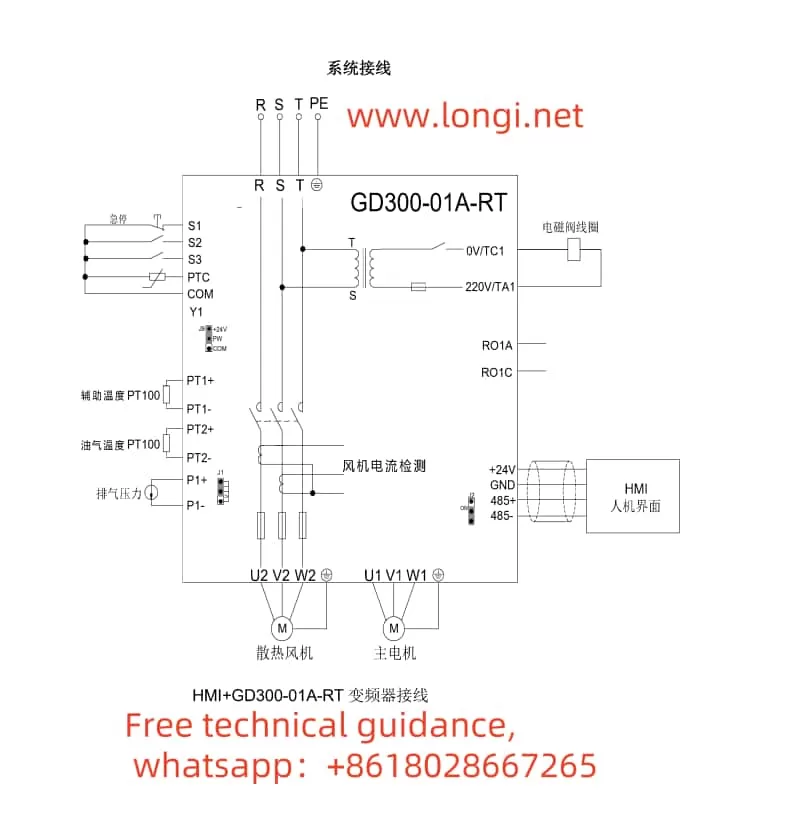
GD300-01A-RT system wiring diagram

III. Setting Password Function and Restoring Factory Settings

  1. Setting Password Function
    Enter the “Human-Machine Interface Group” parameter settings and locate the P07.00 (user password) parameter.
    Enter the desired password value (0~65535) and save the settings.
    After setting the password, the correct password must be entered for parameter modification.
  2. Restoring Factory Settings
    Enter the “Basic Function Group” parameter settings and locate the P00.18 parameter.
    Set P00.18 to 1 (restore default values) and save the settings.
    The VFD will automatically restore to the factory default parameter settings.

IV. Fault Analysis and Handling Methods

  1. Fault Code Query
    When a fault occurs in the VFD, first check the fault code on the VFD panel.
    Refer to the “VFD Faults and Countermeasures” section in the manual based on the fault code to find possible fault causes and corrective actions.
  2. Fault Troubleshooting Steps
    Check the power supply and wiring: Ensure normal power input and secure wiring.
    Check external control signals: Ensure normal input of external control signals (e.g., start, stop, load, unload).
    Check sensor signals: Ensure normal input of signals from pressure sensors, temperature sensors, etc., and correct range and calibration point settings.
    Check the motor and load: Ensure normal motor operation and no abnormalities in the load.
  3. Fault Handling Examples
    Overcurrent Fault (OC1, OC2, OC3):
    Check if the grid voltage is too low.
    Check for short circuits or locked rotor phenomena in the motor and load.
    Increase the acceleration/deceleration time or select a VFD with a higher power.
    Overvoltage Fault (OV1, OV2, OV3):
    Check if the input power voltage is too high.
    Check for energy feedback phenomena and add energy consumption braking components if necessary.
    Undervoltage Fault (UV):
    Check if the grid voltage is too low or fluctuating significantly.

By following this usage guide, users can better grasp the operation of the Invt GD300-01A-RT Series VFD dedicated for air compressors, ensuring stable operation of the air compressor system.

Posted on Leave a comment

INVT Servo SV-DA200 Series Manual User Guide

I. Implementation of Servo JOG Jogging Operation

Implementation Process

Servo JOG (Jogging) operation allows users to manually control the servo motor for short, small movements, primarily used for debugging or precise positioning. The following are the specific steps to implement servo JOG operation:

1. Hardware Connection

  • Connect the Servo Motor: Ensure the servo motor is properly connected to the servo drive, and check that all connecting cables are secure.
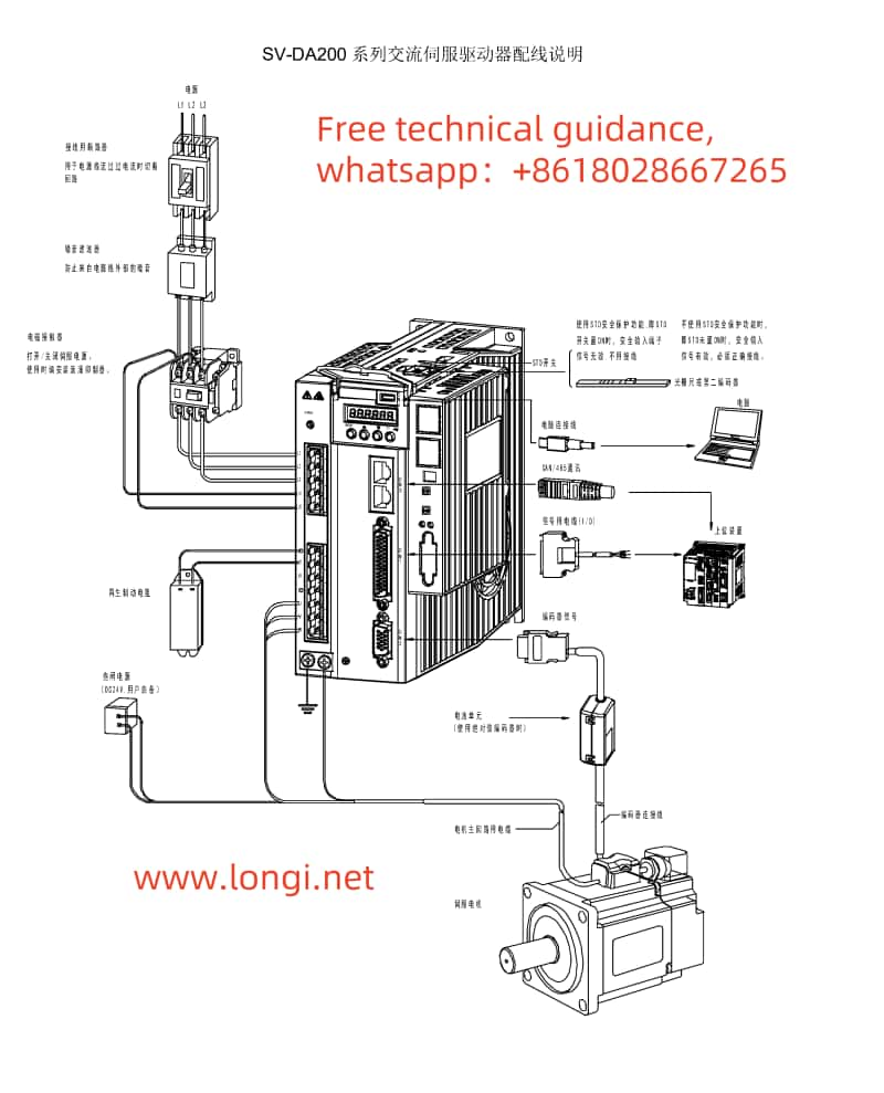
  • Control Signal Wiring: According to the CN1 terminal wiring diagram for the DA200 series servo drive, connect the control signal wires to the corresponding CN1 terminals on the servo drive. For JOG operation, typically, servo enable (SON), direction control (e.g., POT, NOT), and jog signal lines need to be connected.

2. Parameter Settings

  • Set the Motor Model: Use parameter P0.001 to set the correct motor model to ensure the drive can recognize the connected motor.
  • Configure JOG-related Parameters:
    • Jogging Speed: Set the jogging speed through parameter P0.05, typically in units of r/min.
    • Digital Input Configuration: In the P3.xx series of parameters, configure the digital input functions for servo enable (SON), forward jog (e.g., FJOG), reverse jog (e.g., RJOG), and other related inputs as needed.

3. Software Operation

  • Enable the Servo: Activate the servo drive by providing a valid signal to the servo enable terminal (SON).
  • Execute JOG Operation: Apply a forward jog (FJOG) or reverse jog (RJOG) signal, and the servo motor will move at the set jogging speed. Control the duration of the jog signal to manage the motor’s movement distance.

Precautions

  • Ensure safety during JOG operations to prevent accidental movements that could cause harm.
  • Check all connecting cables and parameter settings to ensure correct operation.
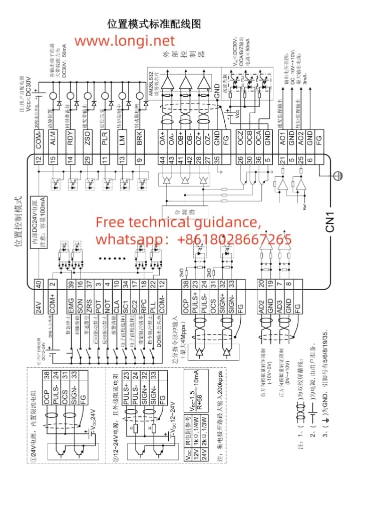
SV-SD200 Position Mode Standard Wiring Diagram

II. Servo Positioning via External Pulses in Position Control Mode

Implementation Process

In position control mode, precise servo positioning through external pulse signals is a common application. The following are the implementation steps:

1. Hardware Connection

  • Pulse Signal Lines: Connect the pulse signal lines to the pulse input terminals on the servo drive (e.g., PULS+, PULS- on CN1). Depending on requirements, direction signal lines (SIGN+, SIGN-) may also need to be connected.
  • Encoder Feedback Lines (if required): If encoder feedback is used, connect the encoder cables correctly to the corresponding terminals on the servo drive.

2. Parameter Settings

  • Control Mode Selection: Set parameter P0.03 to 0 for position control mode.
  • Pulse Input Configuration:
    • Configure the pulse input form (e.g., differential input or open-collector output) and direction signal settings.
    • Set the electronic gear ratio (e.g., P0.25, P0.26) to convert external pulses into actual motor shaft movements.
  • Position Control-related Parameters:
    • Adjust position loop gains (e.g., P2.02) and other control parameters as needed.
    • Configure software limits (e.g., P0.35, P0.36) to prevent exceeding safe travel ranges.

3. Software Operation

  • Send Pulse Signals: Transmit pulse signals to the servo drive via an upper computer, PLC, or other control system. The number of pulses determines the motor’s movement distance, while the pulse frequency controls the motor’s speed.
  • Monitor Status: Use the servo drive’s display panel or upper computer software to monitor the servo motor’s actual position and speed.

Precautions

  • Ensure pulse signal quality and stability to prevent positioning inaccuracies due to signal interference.
  • Adjust control parameters according to actual needs to achieve optimal control performance.

III. Fault Code Meanings and Solutions

Common Fault Codes and Solutions

  • Er10-4: Emergency Stop
    • Meaning: The emergency stop signal is active.
    • Solution: Check if the emergency stop button or related input signal lines have been triggered accidentally, clear the fault, and re-enable the servo.
  • Er22-0: Position Deviation Fault
    • Meaning: The actual position deviates significantly from the command position.
    • Solution: Inspect the mechanical transmission components for jams or loose connections, adjust position loop gains and other control parameters as needed.
  • Er25-1: Overcurrent Fault
    • Meaning: The motor current exceeds the rated value.
    • Solution: Check if the motor is overloaded, adjust speed or torque loop gains, and ensure the power supply voltage is stable.
  • Er13-1: Undervoltage Fault
    • Meaning: The main circuit supply voltage is too low.
    • Solution: Verify the power supply voltage, troubleshoot line faults, or adjust the power supply voltage.

Precautions

  • When encountering fault codes, first consult the fault code table for specific meanings and then follow the corresponding solutions for troubleshooting.
  • If faults cannot be resolved, promptly contact technical support or professional maintenance personnel for assistance.

By following the steps and precautions outlined above, users can effectively implement INVT Servo DA200 series JOG jogging operation, position control using external pulses, and fault diagnosis and resolution.

Posted on Leave a comment

Repair Guide for INVT G9 Series Frequency Converter “Crash” Fault

Repair Guide for INVT G9 Series Frequency Converter “Crash” Fault

When dealing with a reported “crash” fault in an INVT G9 series frequency converter, a systematic approach to diagnosis and repair is crucial. This article outlines a step-by-step process based on user feedback, detailed inspection, and successful repair.

INVT INVERTER physical picture

User Feedback and Initial Observations

The user reported that the frequency converter was not operational at the time of the incident, but other machines on the same three-phase power supply experienced abnormalities, leading to a short circuit and tripping. Consequently, the power switch for the frequency converter also tripped. Upon attempting to reset the power switch, it was discovered that the operation panel was no longer displaying any information, prompting the need for repair.

Detailed Inspection and Fault Identification

Upon inspecting the frequency converter, an open circuit was found between the R, S, T terminals and the main DC circuit (P and N). Further disassembly revealed that the copper foil strip connecting to the module had been damaged by an arc. Testing confirmed a short circuit at the three-phase power supply terminal of the module.

Root Cause Analysis

The root cause of the malfunction was traced back to instantaneous short circuits and tripping of other load branches in the power supply, which induced abnormal voltage spikes in the three-phase power supply. These dangerous voltage levels caused the rectifier circuit in the frequency converter module to break down and short circuit. The resulting strong arc burned the copper foil strip and triggered the power switch to trip.

Repair Plan

INVT inverter drive board

Fortunately, the inverter part of the module was still functional, with no signs of bulging or deformation. Therefore, the decision was made to cut off the damaged rectification part of the module and install an additional three-phase rectification bridge. This low-cost repair plan allowed for the reuse of the original three-phase inverter circuit in the module.

Inspection and Troubleshooting

To prevent further abnormalities, the power supply to the inverter section of the module was cut off. A 500V DC voltage was applied from an external repair power supply, but the operation panel displayed “H.00,” and all operations were ineffective. Based on experience, this indicated that the module’s short circuit detection function had activated, causing the CPU to reject all operations.

Further inspection revealed that the overcurrent signals in the fault signal collection and processing circuit were all negative, whereas they should have been positive under normal conditions. Tracing the current detection circuit, it was found that an incorrect overcurrent signal was being output. By disconnecting the overcurrent fault signal, the operation panel’s parameter settings returned to normal, but the start/stop operation still had no response.

Additional Fault Signals and Resolution

Suspecting that there might be other fault signals causing the frequency converter to remain in protection mode, the voltage at the module’s thermal alarm terminal was measured and found to be 3V, lower than the normal 5V. It was hypothesized that the damaged rectification circuit might be outputting a thermal alarm signal. By cutting off the copper foil strip connected to the thermal alarm, the start/stop operation on the operation panel became effective.

Protection Sequence and Final Repairs

The protection sequence of the INVT G9/P9 frequency converter is designed to ensure safe operation. If a fault is detected in the power inverter output section during power-on detection, the SC – output short circuit fault code will be displayed, and all operations will be rejected. Similarly, if an overcurrent signal is detected, “H.00” will be displayed, and all operations will be halted. When a thermal alarm signal is detected, most operations can be performed, but the startup operation is rejected to prevent overheating.

To complete the repair, the damaged copper foil strip lead of the three-phase power supply was cut off, cleaned, and properly insulated. An external three-phase rectifier circuit was connected, and its DC output was introduced to the P and N terminals. Additionally, a thermal protection circuit was installed using a 60℃ normally closed thermal relay, which is connected in series with an NPN type transistor base to the 5V ground circuit. This ensures that the module does not overheat and burn, providing an additional layer of safety.

By following this structured approach, the INVT G9 series frequency converter was successfully repaired, restoring it to full functionality.