Introduction
In the realm of industrial automation, servo drives serve as the critical “muscle” and “brain” of motion control systems, dictating the precision, speed, and stability of machinery. The DPSON DSL200P series, known for its cost-effectiveness and reliability, is widely deployed in packaging machinery, CNC lathes, conveyor systems, and printing equipment. However, like all sophisticated electronic devices, they are susceptible to specific operational faults.
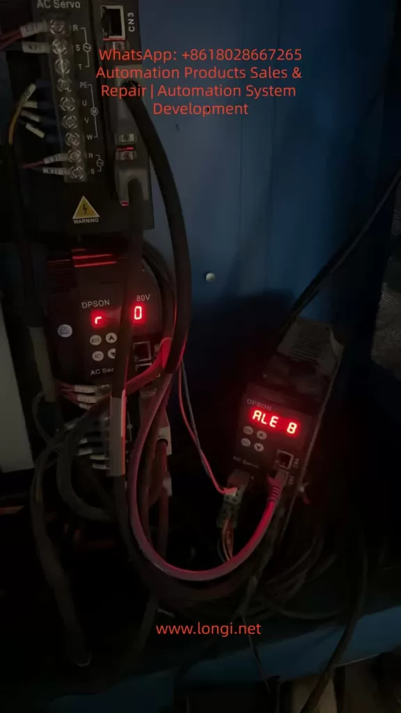
One of the most frequent and disruptive alarms encountered by engineers is ALE08 (Position Deviation Counter Overflow). When this fault occurs, the drive halts the motor abruptly to prevent mechanical damage or motor burnout. If not diagnosed correctly, troubleshooting can be time-consuming, leading to significant production downtime.
This article provides an exhaustive technical analysis of the ALE08 fault. We will dissect the underlying control logic, categorize root causes into mechanical, electrical, and parametric domains, provide a step-by-step diagnostic workflow, analyze real-world case studies, and outline preventive maintenance strategies. This guide is designed for maintenance engineers, system integrators, and automation students seeking a deep understanding of servo dynamics.
I. The Principle of ALE08: Understanding Position Deviation
To effectively troubleshoot ALE08, one must first understand the Closed-Loop Position Control architecture inherent to servo systems.
1. The Control Loop Logic
A servo system operates on a feedback loop:
- Command Input: The host controller (PLC or Motion Card) sends a stream of Command Pulses (representing position or speed) to the drive.
- Feedback Input: The servo motor’s encoder sends Feedback Pulses back to the drive, reporting the actual rotor position.
- Deviation Calculation: The drive’s DSP (Digital Signal Processor) continuously subtracts the Feedback Pulse count from the Command Pulse count. The result is the Position Deviation (or Position Error).
- Correction: Using PID (Proportional-Integral-Derivative) algorithms, the drive adjusts the output voltage/current to the motor to minimize this deviation to zero.
2. The Position Deviation Counter
The Position Deviation Counter is a specific register within the drive’s memory (typically a 16-bit or 32-bit signed integer). It acts as a “bucket” that accumulates the difference between where the motor should be and where it is.
The Overflow Mechanism:
Every servo drive has a maximum limit for this counter (e.g., ±32,767 for a 16-bit system). If the motor fails to follow the command—due to being blocked, lack of torque, or signal loss—the deviation value accumulates rapidly. Once this value exceeds the register’s limit, an overflow occurs. The drive interprets this as a critical failure (the system has lost control of the axis) and triggers ALE08, cutting power to the motor (coast stop or decelerated stop) to protect the machinery.
II. Root Cause Analysis: The Three Domains of Failure
Based on field data and the DSL200P technical manual, the causes of ALE08 can be systematically categorized into three primary domains: Mechanical Load, Command Signal, and Motor/Drive System.
Domain A: Mechanical Load Anomalies (The Most Common Culprit)
This accounts for approximately 60% of ALE08 cases. The issue is not electronic; it is physical. The motor simply cannot generate enough torque to overcome the resistance.
- Excessive Load/Jamming:
- Scenario: A conveyor belt gets stuck on a debris, or a packaging machine hopper gets clogged.
- Physics: The load torque exceeds the motor’s peak torque (e.g., a 750W motor typically offers ~2.39 N·m rated torque, but the instantaneous load demands 5 N·m). The motor stalls, but the controller keeps sending pulses, causing the deviation counter to max out instantly.
- Transmission Component Failure:
- Ball Screw/Lead Screw: Worn nuts, lack of lubrication, or bent shafts increase friction exponentially.
- Belt Drive: Belt snapping, severe slippage, or incorrect tension.
- Bearings: Seized bearings due to contamination or lack of grease.
- Couplings: Failure of the flexible element (spider) in the coupling, disconnecting the motor from the load mechanically while the encoder still reports “zero movement.”
- Foreign Object Intrusion: Metal chips, plastic fragments, or dust entering the screw/nut interface creates a physical barrier.
- Misalignment: The motor axis and the load axis are not concentric, creating binding forces (radial load) that the motor bearings cannot handle.
Domain B: Command Pulse Anomalies (The “Confused” Drive)
If the drive receives incorrect instructions, it cannot calculate the deviation correctly, or the deviation accumulates erroneously.
- Controller/Source Issues:
- Frequency Mismatch: The controller outputs pulses at 300kHz, but the DSL200P is rated for a maximum of 200kHz. The drive misses pulses, leading to calculation errors.
- Electrical Interference (EMI): Noise from nearby VFDs or heavy machinery couples into the pulse line, creating “ghost pulses” or dropping real pulses.
- Hardware Failure: A blown transistor in the controller’s output module.
- Wiring & Connection Faults:
- Loose Terminals: Oxidation or vibration loosening screws on PUL+, PUL-, or SIGNAL GND.
- Cable Damage: Broken shielding or shorted cores in the encoder/pulse cable.
- Grounding Loops: Improper grounding causing reference voltage shifts.
- Parameter Mismatches:
- Electronic Gear Ratio (EGR): If the mechanical reduction is 5:1 but the parameter is set to 1:1, the drive expects the motor to turn 5x faster than it physically can, causing immediate overflow.
- Pulse Equivalent: Incorrect settings for “pulses per millimeter” lead to scaling errors in the deviation calculation.
- Signal Type: Controller sends Differential Line Driver (RS422) signals, but the drive is set to NPN/Open Collector mode.
Domain C: Motor and Drive Output Failures (The “Weak” System)
Even with a perfect command and a free mechanical load, the system might fail to execute.
- Motor Faults:
- Winding Short/Open: The motor generates zero torque.
- Encoder Failure: A dirty code disk or broken cable causes the drive to lose position feedback. The drive thinks the motor isn’t moving (even if it is vibrating) and increases current, eventually triggering an error or overflow as it fights “phantom” resistance.
- Brake Issues: If the motor has a holding brake that fails to release, the motor cannot turn.
- Drive Hardware Faults:
- IGBT Module Damage: One phase of the inverter is dead, resulting in single-phasing. The motor hums but produces insufficient torque.
- Output Line Break: The U/V/W power cable to the motor is severed.
- Current Limit Settings: The “Torque Limit” parameter is set too low (e.g., 20% of rated current), physically preventing the motor from moving a heavy load.
- Incorrect Motor Parameters:
- Auto-Tuning Failure: The drive has not been “tuned” to the specific motor inertia.
- Mismatched Specs: The drive is configured for a 400W motor, but a 750W motor is attached (or vice versa), leading to current saturation.
III. Systematic Troubleshooting Workflow
Follow this “Outside-In” approach to isolate the fault efficiently. Safety First: Disconnect main power before physical inspection.
Step 1: Mechanical Isolation (The “Hand Test”)
Goal: Determine if the load is physically free.
- Power Down: Turn off the main breaker and wait for the drive LEDs to extinguish (capacitors discharge).
- Manual Rotation:
- Direct Drive: Try to turn the motor shaft by hand. It should offer some resistance (magnetic detent) but turn smoothly. If it is locked solid, the motor bearings are seized, or the brake is engaged.
- Belt/Screw Drive: Disconnect the coupling (if possible) and turn the motor side. Then turn the load side.
- Motor turns, Load does not: The jam is in the transmission (screw, bearing, gearbox). Inspect for chips or lack of lube.
- Neither turns: The jam is at the load end (conveyor, axis).
- Inspection: Visually check for broken belts, disconnected couplers, or obvious obstructions.
Step 2: Signal Verification (The “Oscilloscope Test”)
Goal: Verify the integrity of the Command Pulses.
- Reconnect Power: Keep the motor disconnected (or hold the brake) to prevent movement.
- Measure: Connect an oscilloscope to the drive’s PUL+ and PUL- terminals (referenced to SIGNAL GND).
- Analyze Waveform:
- Shape: Look for clean square waves. “Rounded” edges or “stair-stepping” indicates weak drive circuitry or cable capacitance issues. “Spikes” indicate noise.
- Amplitude:
- Differential (RS422): Should be ~2V to 5V peak-to-peak.
- Open Collector (NPN): Should swing from 0V to 24V (or 5V depending on the system).
- Frequency: Command a move (e.g., 10kHz). Does the scope read 10kHz? If it reads 5kHz or 15kHz, the controller or cabling is faulty.
- Check Shielding: Ensure the cable shield is grounded at both ends (Controller and Drive) for high-frequency noise immunity.
Step 3: Parameter & Configuration Audit
Goal: Ensure the “Software” matches the “Hardware”.
Access the DSL200P parameter list (usually via keypad or software). Verify:
- PA01 (Pulse Type): Matches wiring (Differential vs. Open Collector).
- PA02 (Electronic Gear Ratio): Numerator/Denominator matches mechanical reduction (e.g., 1/5 for a 5:1 reducer).
- PA03 (Pulse Equivalent): Correct value for the machine (e.g., 0.001mm/pulse).
- PA05 (Motor Model): Matches the physical motor tag.
- PA10 (Torque Limit): Is it set to 100% or higher? (Sometimes set low for safety testing).
Step 4: Electrical Component Testing
Goal: Test the Motor and Drive power stage.
- Motor Insulation & Resistance:
- Use a Megger (insulation tester) to check U/V/W to Ground (should be >100MΩ).
- Use a multimeter to measure U-V, V-W, W-U resistance. They should be balanced (e.g., all ~1.5Ω). An open circuit (OL) or short circuit (0Ω) indicates burnt windings.
- Encoder Check:
- Rotate the motor shaft by hand slowly.
- Monitor the diagnostic screen (or use a frequency counter) for A/B/Z phase pulses. They should increment/decrement smoothly without dropping counts.
- Drive Output (IGBT):
- Warning: High Voltage. With power on (no run command), measure DC bus voltage (across P/+ and N/-). It should be ~1.41x the input AC voltage (e.g., 320VDC for 220VAC input).
- If the DC bus is low or zero, the rectifier bridge is blown.
IV. Case Studies: Real-World Diagnostics
Case 1: The “Invisible” Jam in a Packaging Machine
- Symptom: Intermittent ALE08 on a sealing bar axis. Manual rotation felt “heavy” but possible.
- Investigation: Mechanical inspection revealed no broken parts. The ball screw was clean. However, the linear guide rails were covered in hardened glue residue from a previous product run.
- Resolution: Cleaning the rails and re-greasing solved the issue. The friction coefficient had increased just enough to exceed the motor’s torque margin during high-speed moves.
Case 2: The Ground Loop Interference
- Symptom: ALE08 occurred only when a large 5kW spindle motor started nearby.
- Investigation: Oscilloscope revealed massive noise spikes on the pulse line coinciding with the spindle start-up. The pulse cable was routed in the same trunking as the 220V spindle power cable.
- Resolution: Re-routing the pulse cable 30cm away from the power cable and installing a ferrite ring (magnetic bead) on the pulse line at the drive end eliminated the noise.
Case 3: Incorrect Electronic Gear Ratio
- Symptom: ALE08 immediately upon starting a “Jog” command, even with the motor unloaded (coupling removed).
- Investigation: The machine was a direct drive (1:1), but the parameter “Electronic Gear” was set to 2:1 from a previous machine setup. The drive was commanding the motor to move twice as fast as the encoder was reporting, causing instant overflow.
- Resolution: Resetting the Electronic Gear Ratio to 1:1 cleared the fault.
V. Prevention and Maintenance Strategy
“An ounce of prevention is worth a pound of cure.” To minimize ALE08 occurrences:
- Mechanical PM Schedule:
- Weekly: Lubricate screws and rails.
- Monthly: Check belt tension and coupler set screws.
- Quarterly: Clean debris from machine tracks.
- Electrical Best Practices:
- Use shielded twisted-pair cables for encoders and pulses.
- Ground the shield at both ends (for servo drives, this is usually preferred over single-point grounding to shunt high-frequency noise).
- Separate power cables (220V/380V) from signal cables (24V/5V).
- Parameter Management:
- Perform a “Backup” of parameters to a USB or PC after every commissioning.
- Document the mechanical reduction ratios and pulse equivalents physically on the machine.
- Operator Training:
- Train operators to recognize the sound of a “stalling” motor (a loud hum) and to hit the E-Stop immediately rather than resetting the drive repeatedly (which can burn the motor).
VI. Common Pitfalls and Safety Warnings
- The “Reset” Trap: Do not simply press “Reset” multiple times. If the mechanical load is jammed, resetting will cause the drive to try to push again, potentially overheating the motor windings or stripping gears. Find the root cause first.
- Ignoring the Encoder: A dirty encoder is a silent killer. If the feedback is lost, the drive assumes the motor is stationary and ramps up current to max, often tripping “Overcurrent” (ALE02) before “Overflow” (ALE08), but sometimes causing ALE08 if the error accumulates subtly.
- Safety: Always assume the motor can move. Secure the load with blocks or jacks before working under it, even if the drive is off (gravity can move vertical axes).
Conclusion
The ALE08 (Position Deviation Counter Overflow) fault on the DPSON DSL200P is a protective mechanism indicating a loss of synchronization between the commanded position and the actual position. While it signals a stop in production, it prevents catastrophic mechanical failure.
By understanding the closed-loop control logic, systematically isolating the problem into mechanical, signal, and parametric categories, and utilizing tools like oscilloscopes and multimeters, engineers can drastically reduce troubleshooting time. Remember that 70% of ALE08 faults are mechanical (friction/jamming), 20% are wiring/interference, and only 10% are drive/motor hardware failures.
Mastering the diagnosis of ALE08 is not just about fixing a single error code; it is about mastering the dynamics of motion control. With the guidelines provided in this article, maintenance personnel can transform from reactive “part changers” into proactive system diagnosticians, ensuring higher uptime and reliability for industrial automation systems.