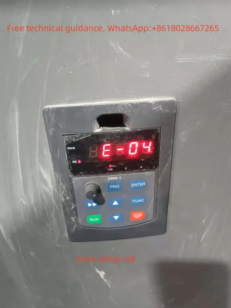
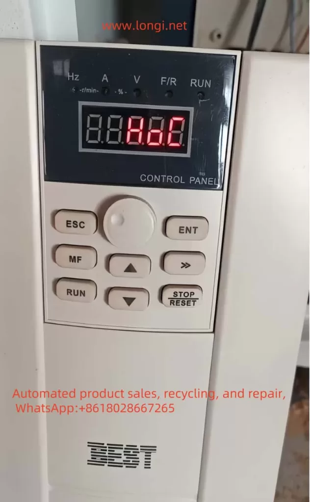
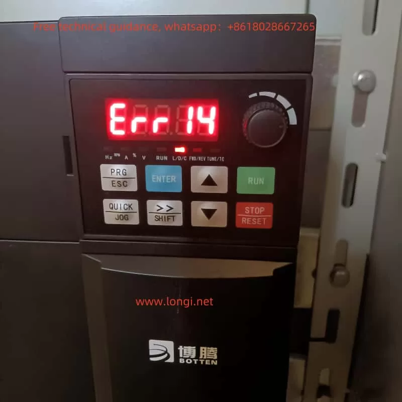
The ERR14 fault displayed on the Botten A900 inverter indicates a specific issue that must be analyzed and resolved for proper operation. This guide will cover the meaning of this fault, potential causes, and detailed repair methods, including electronic circuit analysis.
1. Understanding the ERR14 Fault Code
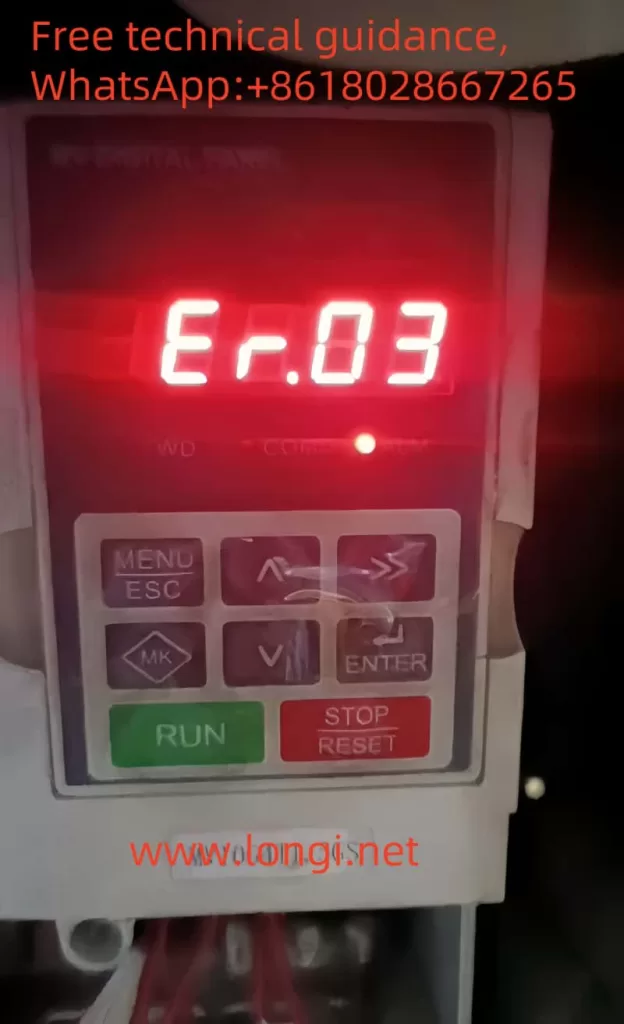
The ERR14 fault in the Botten A900 inverter typically relates to a parameter mismatch, EEPROM error, or data storage issue. This error occurs when the inverter detects inconsistencies or corruptions in the stored data or parameters used for its operation.
Key Meaning of ERR14
- EEPROM Error: The EEPROM (Electrically Erasable Programmable Read-Only Memory) is responsible for storing key operational parameters. If the EEPROM fails to save or retrieve data correctly, the ERR14 fault is triggered.
- Parameter Mismatch: If parameters stored in the EEPROM do not match the expected operational values (due to manual tampering, firmware updates, or memory corruption), this error is displayed.
2. Possible Causes of ERR14
To repair this fault, it’s essential to identify the root cause. Below are some potential reasons:
a. Software/Parameter Issues
- Incorrect parameter input or corruption during setup.
- Power interruption during parameter saving or initialization.
- Firmware update failure, leading to corrupted or mismatched data.
- Overwriting of EEPROM memory due to repeated write cycles.
b. Hardware Issues
- EEPROM Failure: The EEPROM chip may be damaged or unable to retain data properly.
- PCB Track Damage: Faulty PCB tracks or poor soldering can cause inconsistent signals between the EEPROM and the microcontroller.
- Voltage Instability: Power supply fluctuations may damage or temporarily disrupt the EEPROM’s ability to write and read data.
- Microcontroller Fault: The main control IC may fail to communicate correctly with the EEPROM.
c. External Factors
- High-temperature operation leading to degradation of electronic components.
- Environmental factors such as humidity causing corrosion on the PCB.
- Electrostatic discharge (ESD) damage to sensitive components during maintenance.
3. Steps to Diagnose ERR14
Before proceeding with repair, a step-by-step diagnosis is crucial:
a. Preliminary Checks
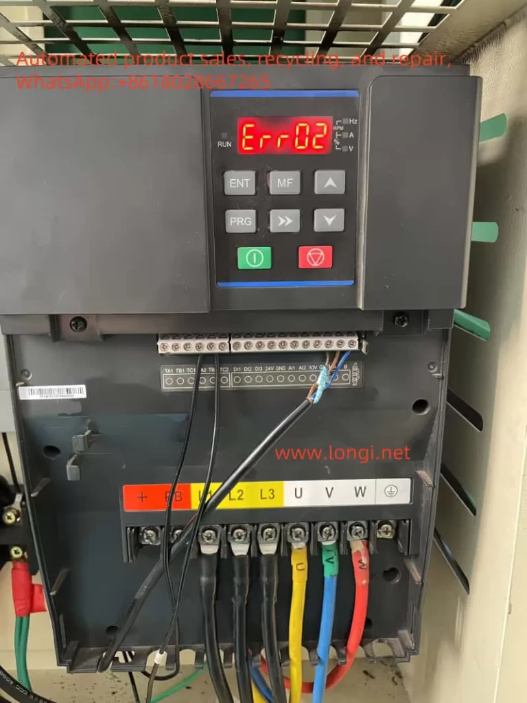
- Reset the Inverter:
- Press the STOP/RESET button.
- Turn off the power for 5-10 minutes to allow a complete reset.
- Power on the inverter and observe if the ERR14 fault persists.
- Restore Factory Parameters:
- Access parameter
P0-00and set it to1to restore default values. - If the fault clears, it indicates a parameter corruption issue.
- Access parameter
b. Advanced Diagnostics
- Check Power Supply:
- Measure the DC bus voltage and ensure stability.
- Inspect the power supply capacitors for bulging or leakage.
- EEPROM Testing:
- Locate the EEPROM chip on the main PCB (often marked as
24Cxxseries). - Use an oscilloscope to verify data signal integrity on the EEPROM pins during read/write operations.
- Replace the EEPROM if abnormal signals or communication failures are detected.
- Locate the EEPROM chip on the main PCB (often marked as
- Microcontroller Testing:
- Verify the connections between the microcontroller and EEPROM.
- Inspect for loose solder joints or damaged tracks using a magnifying glass.
- Environmental Inspection:
- Examine the PCB for signs of corrosion or contamination.
- Clean the board using isopropyl alcohol and a soft brush if necessary.
4. Repair Methods for ERR14
Based on the diagnosis, apply the following repair methods:
a. Software/Parameter Repairs
- Firmware Reinstallation:
- Obtain the latest firmware version from the manufacturer.
- Use a USB or serial communication tool to flash the inverter’s firmware.
- Reinitialize parameters after installation.
- EEPROM Reset:
- Replace parameter settings with factory defaults (via
P0-00). - If this does not work, proceed to hardware repairs.
- Replace parameter settings with factory defaults (via
b. Hardware Repairs
- EEPROM Replacement:
- Desolder the faulty EEPROM chip using a hot air rework station.
- Replace it with a new chip of the same model.
- Reprogram the EEPROM with default parameters if required.
- Microcontroller and Signal Line Repair:
- Check for continuity between the EEPROM and the microcontroller using a multimeter.
- Reflow solder joints on the microcontroller and EEPROM to fix potential cold joints.
- PCB and Power Circuit Repair:
- Inspect the voltage regulators and capacitors on the PCB.
- Replace any damaged components to ensure stable power supply to the EEPROM and other ICs.
c. Preventive Maintenance
- Environmental Protection:
- Apply conformal coating to the PCB to protect against moisture and dust.
- Ensure the inverter is installed in a well-ventilated area to prevent overheating.
- Regular Parameter Backups:
- Periodically back up parameters to an external storage device or memory module to reduce recovery time in case of future errors.
5. Summary
The ERR14 fault on the Botten A900 inverter is primarily related to EEPROM or parameter inconsistencies, and it requires a systematic approach for resolution. By following the detailed diagnostic and repair steps provided, you can efficiently identify and rectify the root cause. Below is a concise summary:
- Perform basic resets and factory parameter initialization.
- Test the EEPROM and microcontroller connections for hardware integrity.
- Replace or reprogram faulty components if necessary.
- Implement preventive measures to minimize future occurrences.
With proper repair and maintenance, the Botten A900 inverter can continue to operate reliably in industrial environments.