Introduction
The SQ1000 series inverter, manufactured by Suqu, is a robust and versatile piece of industrial equipment designed to deliver high torque, precision, and a wide range of speed adjustments for various mechanical applications. Its advanced control technology and adaptability to harsh environmental conditions—such as fluctuating power grids, extreme temperatures, humidity, and dust—make it a popular choice in industrial settings. However, like any sophisticated machinery, it can encounter operational issues, one of which is the E-15 fault code. According to the SQ1000 Series Inverter Detailed Manual, the E-15 code signifies “undervoltage during operation.” This article provides an in-depth exploration of what this fault code means, its potential causes, and a comprehensive guide to troubleshooting and preventing it, based on the user-provided image and manual references.
What is the E-15 Fault Code?
Definition and Significance
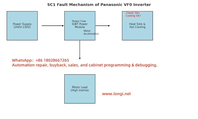
The E-15 fault code on the SQU1000 inverter indicates that the device has detected an input voltage below the acceptable threshold while it is actively running. This undervoltage condition triggers a protective mechanism to halt operation, preventing potential damage to the inverter or the connected motor. The manual (page 66) lists E-15 under the fault code table, explicitly associating it with “undervoltage during operation.” The undervoltage protection threshold is typically governed by parameter F8.02, which defines the voltage level below which the inverter will trip. For instance, if F8.02 is set to 160V, the inverter will display E-15 and stop if the input voltage drops below this value during operation.
This fault is significant because it not only interrupts the inverter’s functionality but also signals an underlying issue that could affect the entire system. Ignoring or repeatedly encountering this fault without resolution may lead to reduced equipment lifespan, motor instability, or production downtime.
Insights from the Image
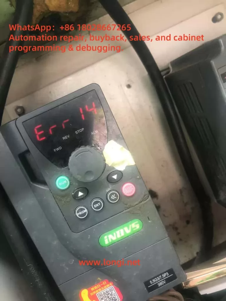
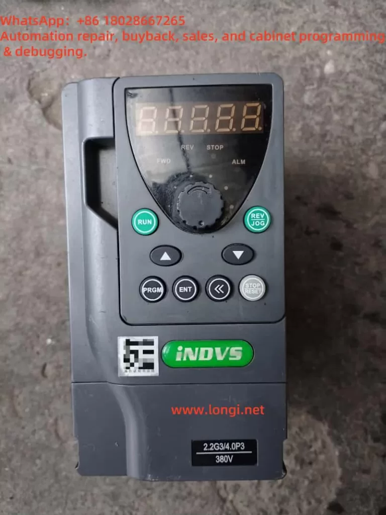
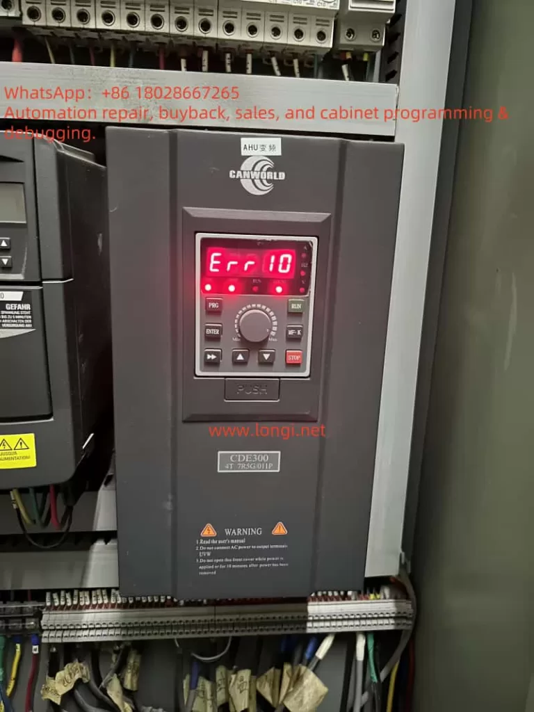
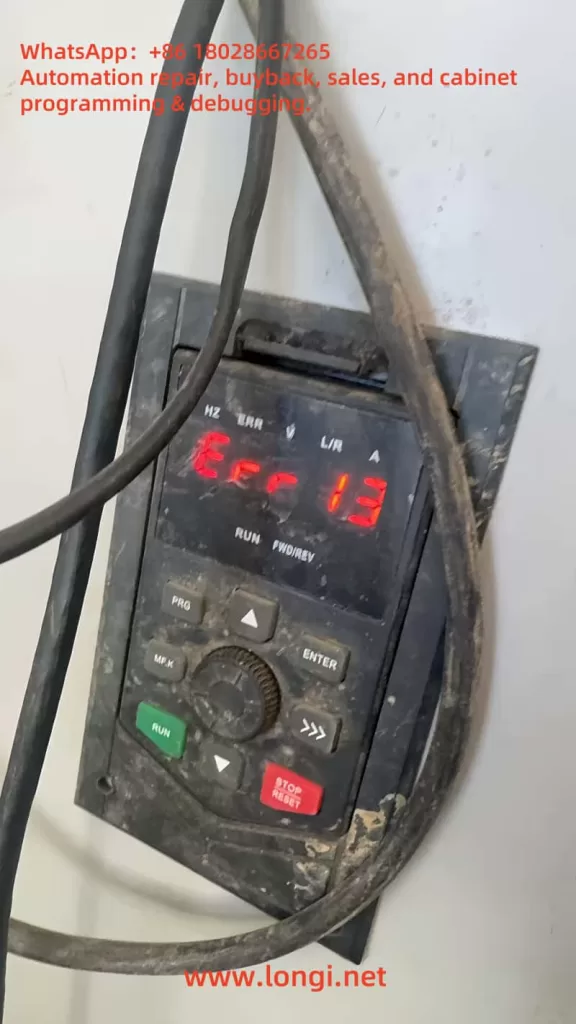
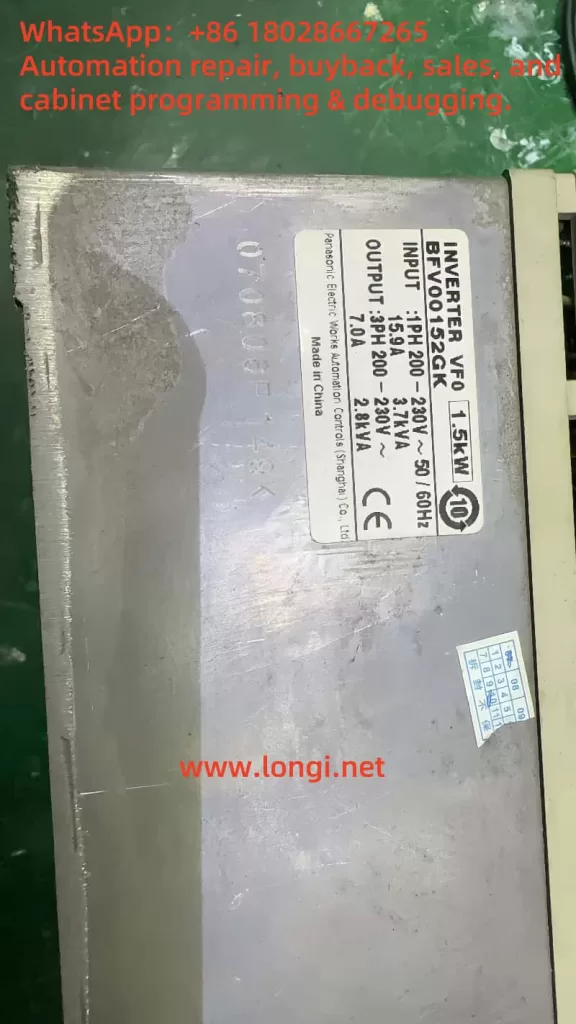
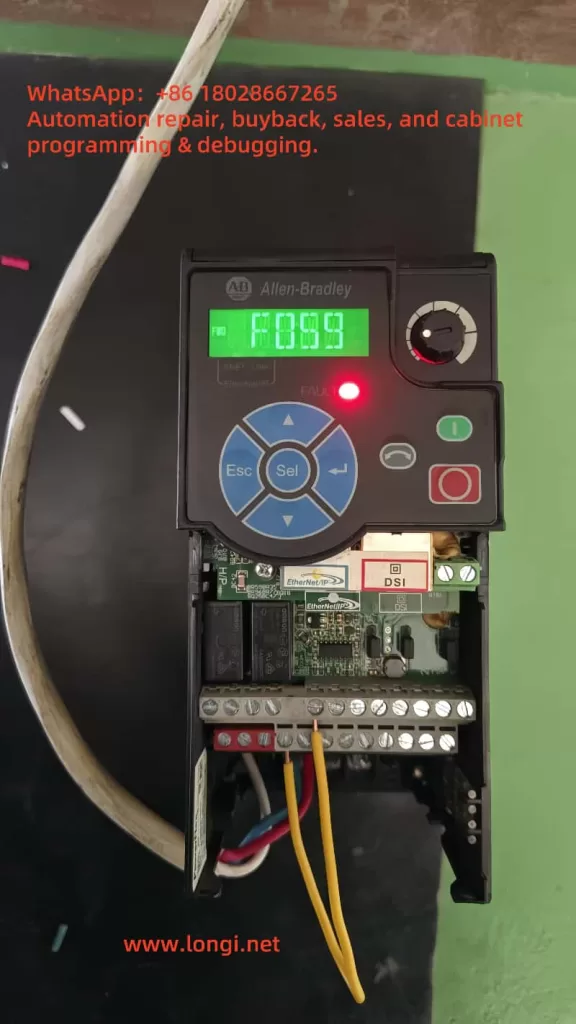
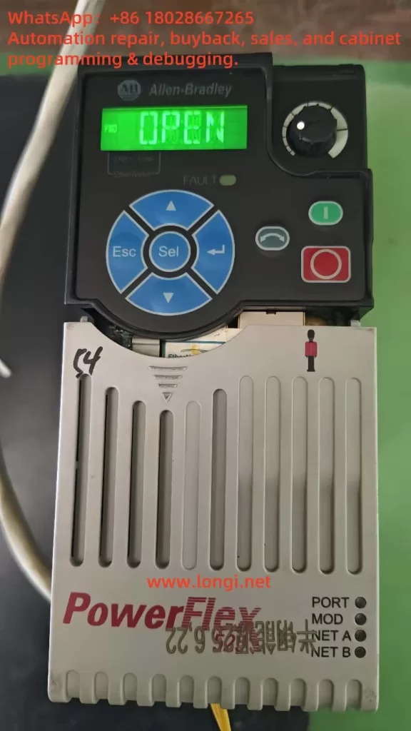
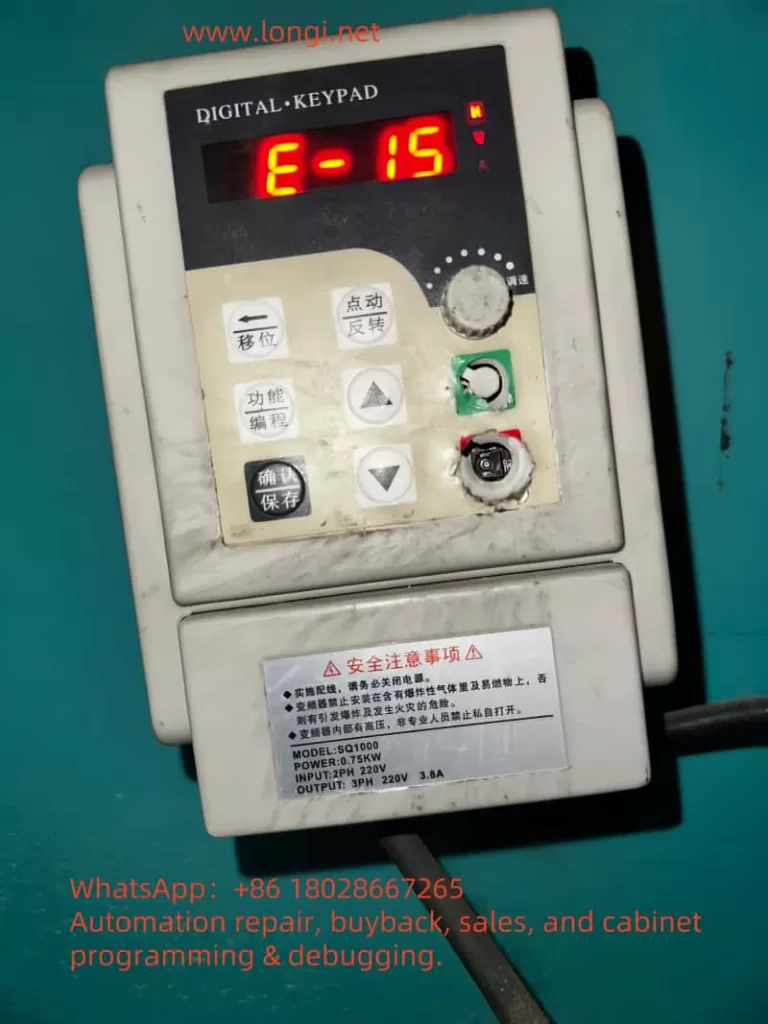
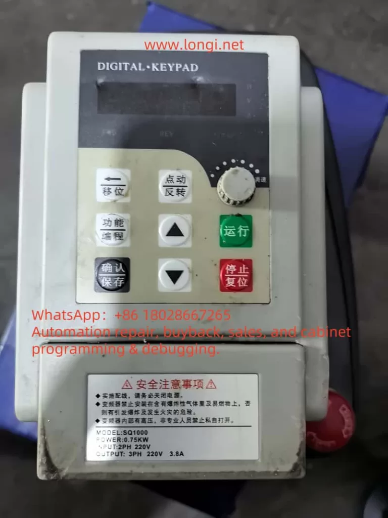
Th image shows an SQ1000 inverter with a power rating of 0.75 kW, configured for single-phase 220V input and three-phase 220V output, with a rated current of 3.8A. The operation panel displays “E-15” on its five-digit LED screen, accompanied by a flashing red display, indicating an active fault state. The “V” indicator light is illuminated, suggesting that the fault pertains to voltage. The panel includes control buttons such as “Shift,” “Function/Program,” “Confirm,” “Up/Down,” and “Stop/Reset,” which are essential for troubleshooting and parameter adjustments. The inverter’s surface shows signs of dust and wear, hinting at operation in a challenging industrial environment, which may contribute to the fault’s occurrence.
Potential Causes of the E-15 Fault
The E-15 fault can stem from various sources, ranging from external power supply issues to internal inverter malfunctions. Based on the manual and practical considerations, the following are the primary causes:
- Unstable Input Power Supply
The manual (page 7) specifies that the SQ1000 inverter operates within an input voltage range of 220V ± 20% (176V–264V for single-phase models) or 380V ± 15% (323V–437V for three-phase models). Voltage fluctuations beyond these limits, common in industrial settings during peak load times, can trigger the E-15 fault. - Power Line Issues
Excessive line length or undersized wire gauge can cause significant voltage drops. The manual (page 11, Chapter 3: Installation and Wiring) emphasizes the importance of reliable power connections to minimize such drops, recommending that voltage loss remain below 5%. - Insufficient Power Supply Capacity
If the power transformer or supply source cannot handle the combined load of the inverter and other equipment, the voltage may sag, leading to undervoltage conditions. - Internal Inverter Faults
A malfunction in the inverter’s power detection circuit or drive board could falsely detect low voltage. The manual (page 67) suggests that persistent fault displays despite normal voltage may indicate drive board or output module issues. - External Electromagnetic Interference
While the SQU1000 boasts good electromagnetic compatibility (page 3), strong interference from nearby equipment, such as large motor startups, could disrupt voltage sensing, causing erroneous fault triggers.
Troubleshooting the E-15 Fault
Resolving the E-15 fault requires a systematic approach to identify and address the root cause. Below is a step-by-step guide:
Step 1: Verify Input Power Supply
- Action: Measure the voltage at the inverter’s input terminals (R, S, T) using a multimeter.
- Expected Range: For the 0.75 kW single-phase model shown in the image, the voltage should be between 176V and 264V.
- Solution: If the voltage is below 176V, consult the local power utility to address grid instability or install a voltage stabilizer (e.g., UPS) upstream of the inverter.
Step 2: Inspect Power Lines and Connections
- Action: Check the power cable length, wire gauge, and terminal connections for adequacy and security.
- Guideline: Ensure the voltage drop across the line is less than 5% of the supply voltage.
- Solution: Replace undersized or overly long cables with appropriately rated ones and tighten any loose connections at the input terminals.
Step 3: Assess Power Supply Capacity
- Action: Evaluate the transformer or power source capacity relative to the total load.
- Solution: If insufficient, upgrade the transformer or reduce concurrent loads on the same circuit.
Step 4: Review Parameter Settings
- Action: Access parameter F8.02 via the operation panel (page 62, manual):
- Press “Function” to enter the main menu.
- Use “Up/Down” keys to navigate to F8 group.
- Press “Confirm” to select F8.02 and check the undervoltage threshold (default may be 160V).
- Solution: If the threshold is set too high for the local grid (e.g., above typical voltage levels), lower it to a safe value like 150V, ensuring the inverter is stopped during adjustment.
Step 5: Check Inverter Hardware
- Action: If the power supply and parameters are normal, inspect internal components:
- Open the inverter (after disconnecting power and waiting five minutes, per safety guidelines on page 5) and check input terminal connections.
- Test the drive board and power detection circuit with professional tools (e.g., oscilloscope), as suggested on page 67.
- Solution: Tighten loose connections or replace faulty components (e.g., drive board) with assistance from the manufacturer.
Step 6: Mitigate External Interference
- Action: Assess the environment for electromagnetic interference sources (e.g., large motors).
- Solution: Install an EMI filter at the input or relocate the inverter away from interference sources. Ensure proper grounding (page 15, manual).
Step 7: Reset and Test
- Action: Press “Stop/Reset” on the panel (page 24) to clear the fault, then restart the inverter.
- Solution: If E-15 persists, repeat the steps or seek professional service, as persistent faults may indicate deeper hardware issues.
Preventive Measures
To minimize future E-15 faults, consider these proactive steps:
- Regular Voltage Monitoring: Use a voltmeter to check input voltage during peak operation periods, ensuring stability within the 176V–264V range.
- Optimized Wiring: Adhere to the manual’s wiring recommendations (Chapter 3), using adequately sized cables and minimizing line lengths.
- Protective Equipment: Install a voltage stabilizer or UPS to buffer grid fluctuations.
- Routine Maintenance: Clean the inverter periodically to remove dust (page 3) and inspect connections for wear, enhancing reliability.
- Parameter Tuning: Adjust F8.02 based on local grid conditions to avoid overly sensitive tripping, balancing safety and functionality.
Conclusion
The E-15 fault code on the SQ1000 inverter, indicating undervoltage during operation, is a critical alert that demands prompt attention to maintain operational efficiency and equipment longevity. By understanding its causes—ranging from power supply instability to internal faults—and following a structured troubleshooting process, users can effectively resolve the issue. The provided image and manual serve as valuable references, confirming the fault’s nature and guiding precise interventions. Implementing preventive measures further ensures the inverter’s robust performance, minimizing downtime and enhancing productivity in industrial applications. With this comprehensive approach, users can confidently manage and mitigate the E-15 fault, leveraging the SQ1000’s advanced capabilities to their fullest potential.