Debugging, application, and maintenance techniques for industrial control products,Such as Variable speed driver(VSD),Variable frequency driver(VFD),Industrial touch screen,Programmable Logic Controller(PLC),Servo Driver,servo motor,servo amplifier,Servo Controller,etc.
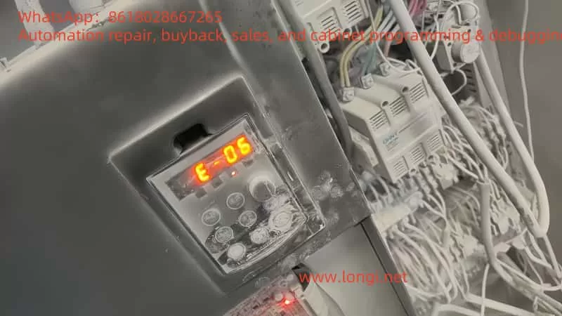
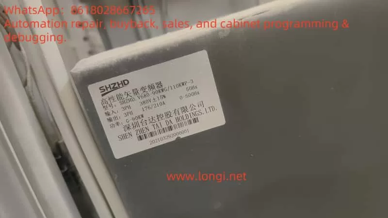
The E-06 fault indicates a deceleration overvoltage, a common issue that can occur during the deceleration process of the SHZHD.V680 variable frequency drive. When the output voltage exceeds the safe range during deceleration, the drive triggers a protection mechanism, leading to equipment shutdown or alarms. This fault is often related to motor load characteristics, parameter settings, and over-excitation control.
2. Fault Cause Analysis
Improper Over-Excitation Settings: Low over-excitation gain settings can cause the voltage to rise too quickly during deceleration.
Load Characteristics: Loads with high inertia can generate excessive reverse electromotive force during deceleration.
Unreasonable Parameter Settings: Short deceleration times can cause the voltage to rise too quickly during deceleration.
3. Solutions
3.1 Adjust Over-Excitation Gain
Parameter P3-10 (VF Over-Excitation Gain): Increase this value to better suppress voltage rise during deceleration. Recommended range: 0 ~ 200. Gradually increase based on actual conditions until the fault is resolved.
3.2 Optimize Deceleration Time Settings
Parameter P0-18 (Deceleration Time 1): Extend the deceleration time to make the deceleration process smoother. Gradually increase based on actual load characteristics until the fault is resolved.
3.3 Check Load Characteristics
If the load has high inertia, additional braking measures, such as adding a braking resistor or using a regenerative system, may be necessary during deceleration.
3.4 Check Motor and Drive Compatibility
Ensure that the motor and drive parameters are matched to avoid overvoltage issues due to mismatched parameters.
4. Precautions
Adjust parameters gradually to avoid introducing other issues.
Conduct trial runs after adjustments to confirm that the fault has been resolved.
If the problem persists, consult technical support or a professional repair technician for further diagnosis.
5. Conclusion
By appropriately adjusting the over-excitation gain, optimizing deceleration time settings, checking load characteristics, and ensuring motor and drive compatibility, the E-06 deceleration overvoltage fault in the SHZHD.V680 variable frequency drive can be effectively resolved. Proper parameter settings and regular maintenance are key to ensuring the efficient operation of the drive.
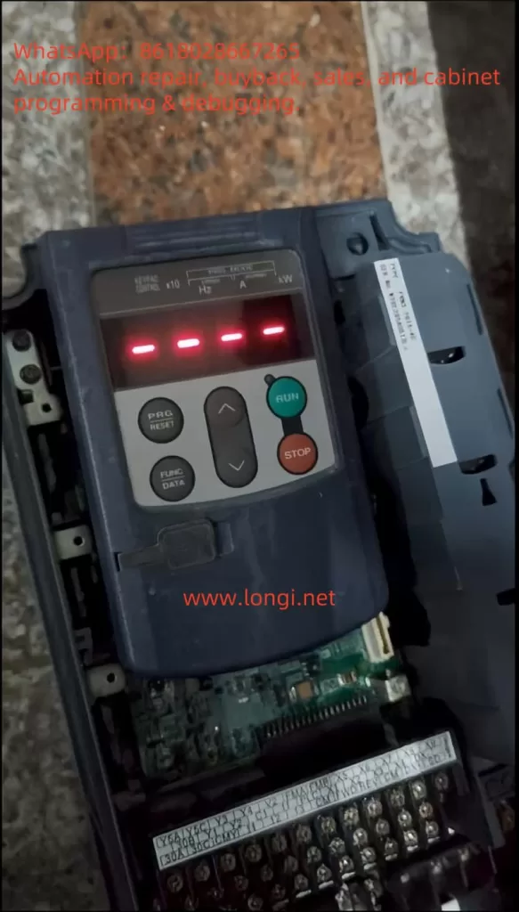
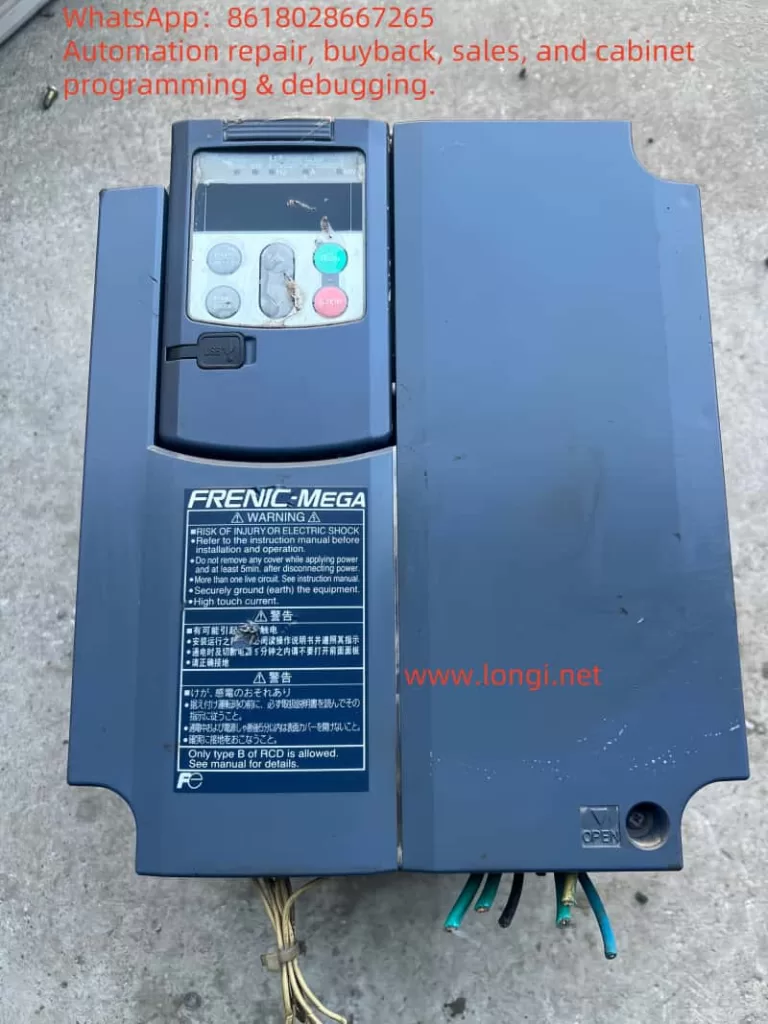
As a key device in the field of industrial control, Fuji Inverter G1S series indicates fault states through different forms of horizontal lines on its operation panel. Based on extensive field cases and technical data, this article provides a comprehensive analysis of horizontal line faults (including the middle horizontal line “—-” and the upper and lower horizontal lines) and offers actionable diagnostic procedures and solutions.
I. Fault Patterns and Core Implications
1. Middle Horizontal Line “—-” Fault
Display Feature: The LED monitor displays four consecutive horizontal lines. Core Implication:
PID Control Conflict: When J01=0 (PID control is not enabled), if the E43 parameter is forcibly set to display PID parameters, the system will return invalid data.
Communication Link Anomaly: Poor connection between the operation panel and the inverter body, such as damage to the shield layer of the extension cable or oxidation of the cable.
2. Lower Horizontal Line “_ _ _ _” Fault
Display Feature: The motor stops after the command is triggered, and the panel displays an underscore. Core Implication:
Insufficient DC Bus Voltage: The measured voltage is below DC400V (for 400V models), often caused by non-compliant input power specifications or excessive line voltage drop.
Missing Main Power Supply: The control power is on, but the main power circuit breaker is not closed.
Power Configuration Conflict: When H72=1, an abnormal main power supply is detected, such as DC power supply incorrectly connected to the AC input terminal.
II. Standardized Diagnostic Procedures
Step 1: Quick Status Confirmation
Power Supply Check:
Main Power Supply: Measure the voltage between L1-L2-L3 to confirm compliance with the inverter specifications (e.g., 400V ±10%).
Control Power Supply: Check the stability of the 24V auxiliary power supply to avoid OC3 alarms caused by fan shorts.
Panel Operation Verification:
Perform a reset operation (long press the RST key) to observe if the fault can be cleared.
Read the communication error counter through parameter viewing mode (e.g., d001-d005).
Step 2: Layered Fault Location
Fault Layer
Inspection Item
Technical Details
Communication Layer
Extension Cable
Use a megohmmeter to measure the cable insulation resistance >10MΩ and check the continuity of the shield layer.
Power Layer
DC Bus
Measure the P(+)-N(-) voltage during startup and compare it with the value displayed on the operation panel (error should be <5%).
Control Layer
Parameter Configuration
Focus on checking critical parameters such as J01 (PID control) and H72 (main power detection).
Step 3: In-Depth Hardware Inspection
Main Circuit Check:
Disconnect the main power supply and measure the resistance of the rectifier bridge and IGBT module to check for short circuits.
Check the connection status of the braking resistor to avoid OU1/OU2 overvoltage alarms.
Control Board Check:
Use an oscilloscope to monitor the PWM output waveform of the mainboard to confirm the integrity of the drive signal.
Perform a “hot swap” test on suspected faulty boards to locate the specific damaged component.
III. Practical Cases of Typical Faults
Case 1: Lower Horizontal Line Fault in a Plastic Extruder
Fault Phenomenon: The motor does not respond after the start command, and the panel displays a lower horizontal line. Diagnostic Process:
Measure the main power supply voltage at 380V (standard 400V), confirming excessive voltage drop.
Check the DC bus voltage at 360V (standard ≥400V), locating insufficient voltage.
Find an incorrect transformer tap setting, resulting in low input voltage. Solution:
Adjust the transformer tap setting to the 400V output position.
Install an APFC device to improve power quality.
Case 2: Middle Horizontal Line Fault in a CNC Machine
Fault Phenomenon: The panel displays “—-” after parameter modification. Diagnostic Process:
Find that E43 is mistakenly set to PID feedback value, while J01=0.
Check the panel extension cable and find that the shield layer is worn at the cable tray. Solution:
Change E43 to frequency display mode.
Replace the shield cable and optimize the cable routing path.
IV. Preventive Maintenance Strategies
Periodic Inspection Plan:
Daily: Visually inspect the panel display status and record the operating environment temperature and humidity.
Monthly: Measure the main power supply voltage, DC bus voltage, and calibrate PID control parameters.
Quarterly: Perform a main power supply power-off restart test and check the contacto r suction status.
Spare Parts Management Optimization:
Establish a lifespan model for critical spare parts (e.g., IGBT modules, DC capacitors).
Sign an emergency supply agreement with suppliers to ensure a 48-hour response.
Technology Upgrade Path:
Regularly upgrade firmware versions to utilize new algorithms for optimizing fault detection mechanisms.
Consider an overall upgrade to the G1S-P series for aging equipment (>5 years).
V. Technical Development Trends
With the development of industrial IoT technology, Fuji Inverter G1S series now supports remote monitoring and predictive maintenance functions. By integrating edge computing nodes, the following can be achieved:
Real-time Fault Feature Extraction: Utilize AI algorithms to analyze waveform data and identify potential faults in advance.
Cloud Expert Diagnosis: Upload fault data to the cloud platform for expert system solutions.
Digital Twin Applications: Build a virtual model of the equipment to simulate fault scenarios and practice response drills.
Conclusion
Handling horizontal line faults in Fuji Inverter G1S series requires engineers to possess a solid knowledge of power electronics and a systematic diagnostic mindset. The standardized procedures and practical cases provided in this article enable users to quickly locate more than 80% of common faults. For complex issues, it is recommended to combine official technical documentation and dedicated diagnostic tools for in-depth analysis. Continuous technical training and knowledge updating are the keys to improving fault handling efficiency.
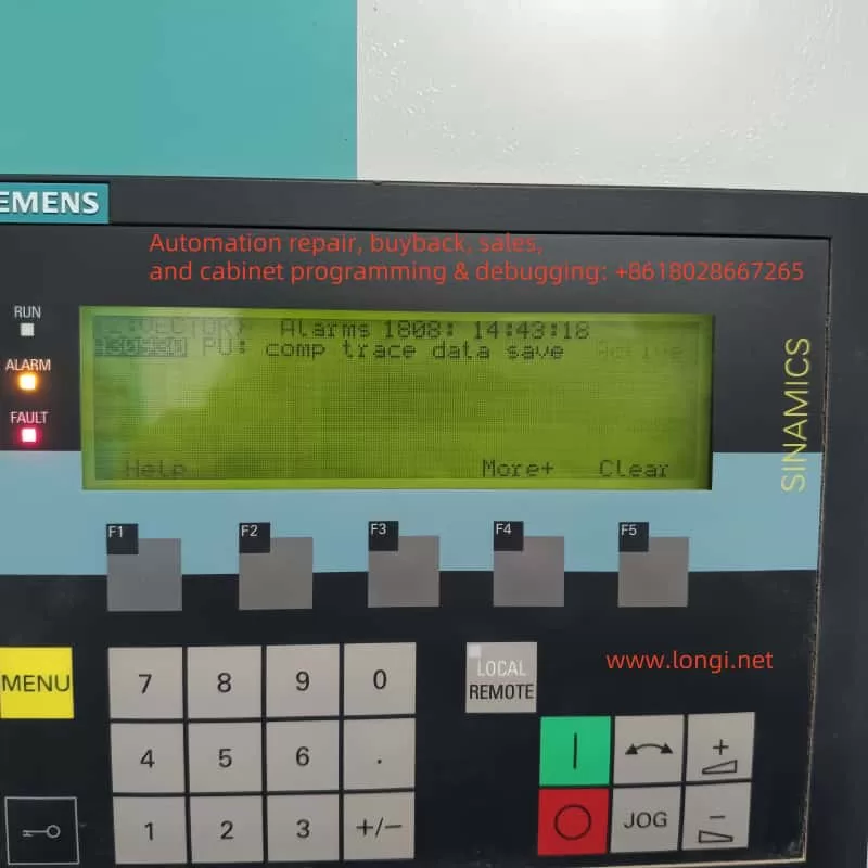
In modern industrial automation, Siemens SINAMICS S120 drives are widely employed across various applications such as CNC machine tools, textile machinery, printing presses, papermaking equipment, robotics, and other sectors demanding high dynamic performance and precision. SINAMICS S120 offers a modular design, advanced control capabilities, and a robust diagnostic system. When an abnormal condition occurs or when the drive simply wishes to notify the user of a particular state, it displays corresponding alarm or fault codes on the Basic Operator Panel (BOP), in the STARTER/TIA Portal software, or on an external HMI (Human-Machine Interface).
Among the many potential fault and alarm messages, Alarms 1080—often accompanied by the text “comp trace data save”—commonly appears in actual usage. Some engineers or first-time users of S120 may misinterpret this alarm as a sign of major damage or serious malfunction. However, Alarms 1080 is typically an information-level or process-level alert, indicating that the drive is saving trace (data logging) information. It is neither a hardware breakdown nor a critical fault demanding immediate shutdown. Understanding and properly handling this alarm is important for maintaining the stability of the drive system and prolonging equipment life. This article will thoroughly explain Alarms 1080’s background, implications, and recommended actions.
2. Definition and Background of Alarms 1080
2.1 Overview of the Trace Function
Siemens SINAMICS S120 includes a built-in Trace (data logging or “oscilloscope”) feature. This function records specified operating parameters or signals (e.g., current, speed, position feedback, torque commands) within the drive’s memory. When the Trace function is enabled—either manually by the user in the engineering software (STARTER or TIA Portal) or triggered automatically by certain system conditions—these signals are sampled at set intervals or in response to defined triggers. The sampled data is then stored in the drive’s internal memory or on a connected storage card (such as a CF card).
Once the sampling cycle or trigger condition is completed, the drive writes or finalizes the captured data. During this process, the drive issues a notification to indicate that it is actively saving data. This valuable dataset can later be analyzed to optimize control parameters or diagnose intermittent or complex errors.
2.2 What Alarms 1080 Signifies
When you see Alarms 1080 with a description along the lines of “comp trace data save” or “Trace data is being saved,” it specifically indicates that the drive is performing the data save operation for an active Trace task.
This message does not imply hardware damage or a system crash.
It is typically a “system event” or “user-level” notification that does not disrupt the drive’s primary function.
2.3 How It Differs from Fault Codes
Unlike “Fault” codes (e.g., F07802, F30003) prefixed with “F,” which usually shut down or block the drive until reset, an alarm such as Alarms 1080 does not force the drive into a faulted or disabled state. Serious faults typically demand manual acknowledgment or system logic to reset them; meanwhile, Alarms 1080 is more akin to an informational prompt. Once data saving completes and no other higher-level issues exist, the system will clear or deactivate the alarm automatically.
3. Common Causes and Scenarios
In practice, Alarms 1080 (“comp trace data save”) most often arises from these scenarios:
Manually Enabled Trace During Commissioning In many cases, an engineer sets up a Trace task in STARTER, TIA Portal, or directly on the panel to diagnose specific motor or drive behavior. For example, if you want to observe speed-loop responses or current-waveform patterns, you configure sampling frequency, trigger conditions, and the signals to track. As soon as the sampling finishes, the drive writes the data to storage, resulting in Alarms 1080.
Automatic Background Trace Some drive configurations automatically initiate the Trace function for advanced monitoring or “fault logging.” When the system detects certain threshold conditions or a fault event, the drive begins collecting data. Once the event is captured, it proceeds to save it, displaying Alarms 1080 in the process.
Leftover Trace Settings In some projects, the Trace function was used at one point but never deactivated. Even after the main commissioning is done, the drive may still be periodically recording data and subsequently saving it, inadvertently causing recurring Alarms 1080 messages. Though typically benign, these messages might raise questions among less-experienced personnel.
4. Impact on System Operation
Because Alarms 1080 is an informational or process-level alert, it does not necessarily prevent normal drive operation or motor control, as long as there are no simultaneous major fault codes. However, keep in mind the following:
Do Not Interrupt Power During Saving If the drive is in the middle of saving Trace data and power is lost or intentionally shut off, it may lead to incomplete data or, in rare cases, corruption of the storage medium. In general, it is best to avoid powering down the drive while Alarms 1080 is active unless absolutely necessary.
Resource Consumption The Trace function may consume a portion of the drive’s internal resources, including CPU and memory. Although typically minimal, high sampling rates combined with large data sets can create significant overhead. If the user no longer needs Trace data, disabling it can free up resources.
Parallel Occurrences with Faults If a severe drive fault (e.g., F07802 “Infeed Not Ready”) appears alongside Alarms 1080, the fault should take priority for troubleshooting. Alarms 1080 in that case merely indicates that trace data related to the fault was captured or saved, but it is not the cause of the fault itself.
5. Handling and Disabling Methods
When you see Alarms 1080 on the drive, and you confirm that a Trace save is in progress, you can use the following approaches to manage or eliminate it:
Wait for the Save to Complete Typically, the drive only needs a short interval—ranging from a few seconds to maybe a minute—for large data sets—to store the captured Trace data. The alarm will then disappear on its own once the operation finishes.
Deactivate or Remove Trace Tasks If data logging is no longer required, you can open the Trace or Recording screen in STARTER or TIA Portal, locate any active Trace configurations, and disable or delete them.
Certain drive operator panels (like BOP20) may also allow you to view or halt ongoing Trace recordings if the firmware supports it.
Check Storage Space and Write Permissions Occasionally, if the alarm persists, the storage medium (internal memory or CF card) might be full, write-protected, or otherwise inaccessible. Ensure you have enough free space or switch to a larger-capacity CF card if needed.
Reset Alarms If Needed Usually, purely informational alarms clear automatically without requiring a reset. However, if Alarms 1080 coincides with an actual Fault, you may need to perform a fault reset (via the panel or a higher-level controller) after addressing the underlying issue.
6. Common Questions and Answers
Q1: “Does the presence of Alarms 1080 mean the drive is damaged?” A1: Not at all. Alarms 1080 almost always indicates that the drive is recording or saving Trace data, not that any component has malfunctioned. If no additional serious alarms or faults are active, the system can continue operating normally.
Q2: “Will repeatedly seeing Alarms 1080 negatively affect the system?” A2: In most cases, no. It simply appears whenever trace-saving occurs. Unless you are sampling enormous volumes of data at high frequencies, system performance typically remains unaffected. If you do not need the Trace feature, consider disabling it to keep messages streamlined.
Q3: “How do I check Trace configurations or the storage location?” A3: Within STARTER or TIA Portal, navigate to the corresponding drive object, and look for “Trace” or “Recording” in the function tree. There, you can view and edit active tracing tasks. On certain operator panels, you might find a Diagnostics → Trace Logs menu that shows ongoing traces and storage status.
Q4: “What else can the Trace function be used for?” A4: Beyond fault diagnosis, the Trace feature is invaluable for capturing transient oscillations, optimizing control loops (like speed-loop gains or filter time constants), and logging multiple signals simultaneously. It helps improve control accuracy and pinpoint root causes of sporadic or short-lived anomalies.
7. Case Study
Consider a textile production line where an engineer needs to diagnose oscillations in the S120 drive. By enabling two Trace channels (one for current loop, one for speed loop) at a high sampling rate, the system collected large volumes of data. While saving these data sets, “Alarms 1080: comp trace data save” appeared repeatedly on the drive’s screen. Initially, on-site maintenance personnel feared a serious error; however, it quickly became clear that the drive was simply finalizing the recording.
Once the trace was stored, Alarms 1080 cleared by itself. Analyzing the newly captured data, the engineer discovered a PID tuning issue. By fine-tuning the relevant parameters, they significantly reduced mechanical vibration. This real-world experience illustrates how Alarms 1080 is part of a normal diagnostic workflow and can be harnessed for performance improvements rather than being an indication of a critical failure.
8. Conclusion
In summary, Alarms 1080 (“comp trace data save”) in the Siemens SINAMICS S120 drive primarily indicates the system is saving Trace data—a process-level or informational message rather than a hardware or software malfunction. Proper use of the Trace function can substantially enhance commissioning and fault diagnosis, making it possible to observe internal drive states and parameter changes in great detail. If you do not need data logging, you can disable or remove the trace configuration to prevent recurrent alarms.
If a severe fault (e.g., an “Fxxxx” code) accompanies Alarms 1080, prioritize investigating the fault itself. Ensure power and wiring integrity, confirm that no IGBT or module fault exists, and only then determine whether to proceed with or discontinue trace logging. But in the absence of critical errors, Alarms 1080 simply signals that the drive is working as intended to capture and save valuable diagnostic data.
By correctly recognizing Alarms 1080 and using it appropriately, maintenance and commissioning personnel can leverage the drive’s powerful built-in diagnostic capabilities without undue worry. This alarm can assist with targeted data capture, enabling users to optimize performance and quickly resolve intermittent failures. We hope this article clarifies the nature of Alarms 1080 in SINAMICS S120 and helps you confidently manage and benefit from its Trace functionality in real-world industrial scenarios.
Application Points and Functions In a desiccant packaging machine, there are often multiple drive motors, such as a feeding motor, a sealing motor, a blower/fan motor, a conveyor motor, and so on. If you are focusing on the “desiccant-blowing” or “air-blowing” process, you can apply the HLP-C100 inverter in the following situations:
Blower/Fan Motor: By using the inverter to control air volume or blowing speed, you can flexibly adjust airflow according to packaging speed or desiccant characteristics.
Conveying/Feeding Motor (if necessary): You can achieve more precise control of the speed at which desiccant moves, preventing blockage or spillage.
Other Auxiliary Mechanisms (e.g., stirring, lifting, rotating, etc.): Based on your needs, you can also equip these with an inverter to implement multi-step speed or jog functionalities.
Control Method Selection
To allow flexible speed adjustment, operators may directly set the speed on the inverter’s front panel using the built-in knob (local control mode), or use an external analog signal (0–10V/4–20mA from a PLC or industrial PC) as a remote speed reference.
If the machine requires centralized automation control (e.g., unified operation from an HMI, production line linkage, recipe management), you can add a small PLC (e.g., Hailipu’s PLC, Mitsubishi FX series, Xinje, Delta, etc.) and an HMI (touch panel) to manage start/stop commands, frequency references, alarm display, and more.
Below, we address main circuit wiring, control circuit wiring, parameter settings, and how to select/connect a PLC/HMI.
II. Main Circuit Wiring
Motor-to-Inverter Connection
Inverter Output Terminals: U, V, W → Connect to the three-phase terminals of the blower/fan motor (if you have a single-phase motor, this will not be suitable unless you use a model that supports single-phase output).
Inverter Input Terminals: R, S, T → Connect to the three-phase AC supply (for single-phase 220 V models, connect to R and T).
Ground Terminal PE: Must be reliably grounded to prevent leakage, interference, and induced voltages.
Refer to the “3.3 Main Circuit Wiring Diagram” in the manual. For smaller motor power ratings (e.g., 0.75 kW to 1.5 kW), the HLP-C100 series is usually sufficient. Ensure that the motor’s rated power, voltage, and current match the inverter’s specifications, leaving some margin.
Peripheral Protection and Input-Side Components
Circuit Breaker (Air Switch): Selected based on the inverter’s rated input current (see “3.2.1 Air Switch, Fuse, Contactor Selection” in the manual) to cut power promptly under overcurrent or other serious faults.
AC Contactor (optional): Avoid using it too frequently for starting/stopping the inverter. Typically, it’s only used for maintenance or emergency power-off situations.
Input Reactor/EMI Filter (optional): If the site has harmonic issues or other sensitive equipment, consider adding an input reactor or EMI filter on the supply side to reduce higher-order harmonics and electromagnetic interference.
Brake Unit and Brake Resistor (optional) For a “blower” load, inertia is usually not large, and fast, frequent deceleration is rarely required, so you typically do not need an external brake unit/resistor. But if this inverter is used with higher-inertia loads or requires rapid stops (such as certain conveying or feeding mechanisms), you may consider using the built-in or external brake unit plus an appropriately sized brake resistor.
Main Circuit Diagram (Text Example)Power R ——┐ │ Power S ——┤—— [Circuit Breaker] —— [HLP-C100 Inverter] —— U —— Motor (UVW) │ V Power T ——┘ W Inverter PE ———— Ground (Earth)(The above example shows a three-phase 380 V connection; for single-phase, omit S and connect R/T to the live/neutral wires.)
III. Control Circuit Wiring
Control circuit wiring determines how the inverter receives start/stop, direction, and frequency commands, and how it outputs fault and run signals. If you need to use a PLC or external buttons for control, refer to the following.
Digital Inputs (DI)
The HLP-C100 provides five digital input terminals (FOR, REV, DI1, DI2, DI3) configured as NPN by default (see “3.4 Control Circuit Wiring” in the manual).
Typically, FOR is set as the “forward run” command, REV as “reverse run” (if necessary), and the remaining DI1, DI2, DI3 can be set up for multi-step speed selection, emergency stop, reset, jog, etc.
For a blower needing only forward run and stop, you can place an external “START” button (normally open) and a “STOP” button (normally closed) to the respective terminals. For example:
FOR = Start (via a normally open button + 24 V power; pressing it gives a high-level signal to the inverter)
DI1 = Stop (via a normally closed button + 24 V; pressing it breaks the circuit, giving a low-level signal to stop)
Or you can assign “start-stop in one” to FOR (reverse logic).
Analog Input (VI)
If you want to adjust blower speed remotely using an external analog signal (0–10 V / 4–20 mA from a PLC or sensor), wire the signal to VI and GND on the inverter.
In the parameters (e.g., C03.15, etc.), select “Reference Source 1 = VI,” and calibrate the range in C06.10~C06.19 to match your actual voltage or current signal.
Relay Output (FA-FB-FC)
If you want a dry contact output from the inverter to indicate a fault or run status, set parameter C05.40 (Relay Output Function) to 9 (Fault), 5 (Running), etc. Then a PLC or external indicator can monitor the inverter state.
Control Circuit Diagram (Text Example)[+24V] —— Start Button (NO) ——> FOR terminal on inverter —— Stop Button (NC) ——> DI1 terminal on inverter GND ---------------------------------> Inverter GND Analog: PLC AO(0-10V) ——> VI PLC AGND ——> GND Relay Output: FA-FB-FC (FB is common, FA is NC, FC is NO)(If you are only using the inverter’s keypad for start/stop and knob for speed, you can omit the digital inputs or just keep a dedicated emergency stop.)
IV. Key Parameter Settings (Example)
Suppose the motor is 0.75 kW, rated voltage 380 V, rated frequency 50 Hz, rated current 1.8 A (example). You want to control start/stop with external FOR and DI1, and 0–10 V analog for speed. Below are key configuration points (see the manual’s “Chapter 5–7: Function Parameter Table” and “Quick Application Guide” for details):
Motor Parameters (Group 01)
C01.20 = Motor Power = 0.75 (kW)
C01.22 = Motor Rated Voltage = 380 (V)
C01.23 = Motor Rated Frequency = 50.0 (Hz)
C01.24 = Motor Rated Current = 1.80 (A)
C01.25 = Motor Rated Speed = 1440 (rpm) (example)
Operating Mode
C01.00 = 0 (Open-loop speed)
Reference Frequency and Acc/Dec (Group 03)
C03.03 = 50.00 (Max Reference; set to 50 if you want up to 50 Hz, or higher if you want 60 Hz, etc.)
C03.15 = 1 (Reference Source 1 = “Terminal VI”)
C03.41 / C03.42 = 5.0 s / 5.0 s (Acceleration/Deceleration time; adjust as needed for the blower’s inertia)
Start/Stop & Direction Control (Group 05)
C05.10 (FOR Input Function) = 8 (“Start”)
C05.12 (DI1 Input Function) = 6 (“Stop, inverse logic”) or 46 (“Stop, normal logic”)
If reverse is not required, set C04.10 (Motor Run Direction) to 0 to allow only forward operation, preventing accidental reverse.
Analog Input (Group 06)
C06.19 = 0 (Indicates VI is a voltage input)
C06.10 = 0.00, C06.11 = 10.00 (0–10 V corresponds to 0–50 Hz)
If you need a zero deadband, set C06.18 accordingly; if the input fluctuates too much, increase C06.16 (filter time), etc.
Protections and Warnings
C04.58 = 0 (Motor phase-loss detection; set to 1 if you need it)
C14.01 = 5 (Carrier frequency, typically 4–6 kHz is fine; lower it if there’s high EMI)
Other defaults (overcurrent, overvoltage, overheat, external faults, etc.) already provide complete protection but can be tuned further if required.
Other Common Functions
Multi-step Speed: Use DI1, DI2, DI3 in combination to set up multi-speed operation (e.g., fast, slow, jog).
PID Control: If you want to control blower pressure or airflow precisely, set C01.00=3 (Process Closed Loop) and configure the PID parameters in Group 07 along with a feedback sensor signal on VI.
Jog: Use C03.11 for jog frequency, and assign a DI (e.g., FOR or DIx) to “jog function.”
V. Using a PLC / Touch Screen / Industrial PC (If Needed)
PLC Selection
For simpler requirements (start/stop, speed reference, minimal I/O), choose a low-end PLC (e.g., Hailipu, Delta, Xinje, Mitsubishi FX1S/FX3U, etc.).
For more comprehensive linkage (e.g., multi-station synchronization, multi-step speeds, fault interlocks), select a mid-range PLC with sufficient I/O.
Communication: The HLP-C100 features RS485 (Modbus RTU). If your PLC has RS485, you can connect them directly with twisted-pair wiring. Through PLC registers, you can read/write the inverter’s operating status, fault info, frequency commands, etc.
Touch Screen / HMI / Industrial PC
If you need HMI operation, you can choose a 7” or 10” screen (e.g., Weintek, Kinco, Hailipu HMI) integrated with the PLC. Alternatively, the HMI can connect directly to the inverter over Modbus RTU.
In the HMI configuration software, set the inverter station address, baud rate, and parity (matching C08.31, C08.32, C08.33) for reading and writing the inverter’s registers. This allows remote start/stop, speed setting, alarm monitoring, parameter/recipe management, etc.
The same applies to an industrial PC, which can connect via serial RS485 or via a USB/RS232-to-RS485 converter.
Wiring and Precautions
RS485 Interface: Inverter terminals RS+ and RS- correspond to the PLC’s D+ and D-. Make sure to include the 120 Ω termination resistor if required (move jumper J1 on the inverter to ON or add an external resistor).
For multiple inverters on one bus, assign distinct addresses (C08.31) and ensure the same baud rate (C08.32) and data format (C08.33).
VI. Wiring and Control Diagram Examples (Dashed-Line Version)
Below is an example for a three-phase 380 V supply, with external push-button start/stop and analog speed control:
              Three-phase AC380V
       R ——┐
       S ——┤—— [Circuit Breaker] ——> [HLP-C100 Inverter] ——> U ——> Blower Motor
       T ——┘                                         V
                                                   W
            PE ————————————> Protective Ground


Digital Control:
   +24V (From PLC or external supply) —— Start Button (NO) ——> FOR (inverter)
                                      —— Stop Button (NC) ——> DI1 (inverter)
   Inverter GND —————————————————————> +24V Supply GND

Analog Signal:
   PLC AO(0–10V) ——> VI (inverter)
   PLC AGND       ——> GND (inverter)

Relay Output (optional):
   FA-FB-FC (FB is common; FA normally closed, FC normally open)
   ——> PLC input or alarm indicator

RS485 Communication (optional):
   PLC D+ ——> RS+  (inverter)
   PLC D- ——> RS-  (inverter)
   Common: PLC COM ——> COM (inverter)
If you only wish to use the inverter’s built-in keypad for start/stop and speed adjustment, there is no need for external push buttons—just ensure C00.40 (HAND Key), C00.42 (AUTO Key) are enabled (default). For speed reference, set C03.15=21 (panel potentiometer).
VII. Conclusion
Advantages of This Scheme:
You can flexibly adjust the blower motor speed (frequency) as required by the desiccant packaging process.
Via external push buttons or PLC/HMI, you can seamlessly switch between automatic and manual control, improving efficiency and convenience.
The inverter includes robust built-in protection features to safeguard both the motor and itself.
Optional and Extended Features:
If your machine requires multi-station linkage or advanced remote monitoring, choose a more capable PLC/HMI and leverage RS485 (Modbus RTU) for centralized control.
If harmonic interference is severe, add an input reactor or EMI filter.
For rapid braking or high-inertia loads, you can configure a brake unit and suitable brake resistor.
If the ambient temperature exceeds 40 °C, derate the inverter or use enhanced cooling to ensure reliable operation.
By following the principles of correct model selection, standardized wiring, and proper parameter configuration, you can fully harness the speed-regulating advantages of the HLP-C100, thereby enhancing the performance and stability of your desiccant packaging machine.
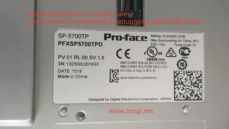
In modern industrial automation, the Human Machine Interface (HMI) plays a critical role in boosting production efficiency and ensuring operational safety. Pro-face, a Japanese brand well-known in the HMI field, has adopted a modular design in its SP series touchscreens: users can freely choose different display sizes and pair them with the appropriate “box modules” to handle complex control tasks. Thanks to this design, the Pro-face SP series is widely used across industries such as machinery manufacturing, electronics assembly, pharmaceuticals, and food processing.
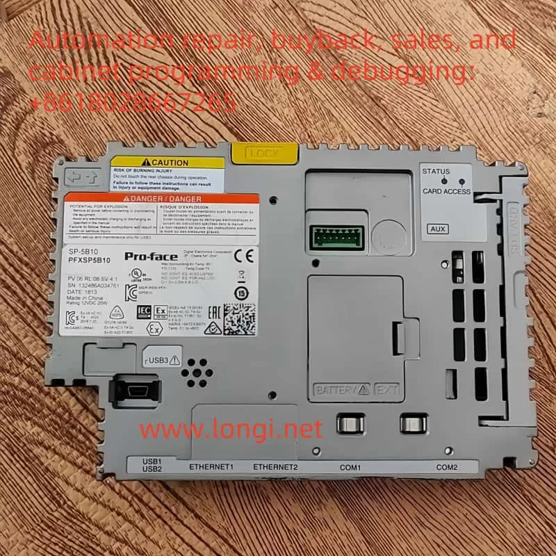
Despite its popularity, many users have questions when disassembling or maintaining an SP series touchscreen. Specifically, they may wonder about the module located on the back that looks like a “power box” or “processor unit.” What function does it serve? If you remove this module, can the display still operate as long as it is powered? This article will take an in-depth look at the Pro-face SP-5B10 (PFXSP5B10) box module—its features and importance, how it interacts with the display module, and whether or not the touchscreen can still function normally once the module is removed.
II. Overview of the Pro-face SP-5B10 Module
1. Module Positioning: The Core Processing Unit of the HMI
The Pro-face SP-5B10 box module (also known as the “enhanced box module” or “Power Box”) is the “brain” of the SP5000 series touchscreen system. It houses the processor, memory, and various industrial communication interfaces. Unlike a traditional, single-unit HMI device, Pro-face introduced a modular approach in the SP series by separating the display section and the processing section, referred to as the display module and the box module, respectively. As the box module, SP-5B10 is in charge of running control logic, storing project data, connecting devices via different networks, and overseeing the overall operation of the system.
2. The “Brain” for Running Business Logic and Display Screens
In practical applications, an HMI often needs to run custom programs for production lines, equipment, or processes—such as displaying workflows, monitoring real-time data, and sending or receiving control commands. These configured screens and logic programs are developed via software like GP-Pro EX and are downloaded to the box module. The SP-5B10 provides ample processing power and memory to execute these screen logics, data collection tasks, and alarm management. It then transmits the resulting display data to the display module. Essentially, without the box module’s processing and control, the HMI’s “intelligence” does not exist, and the touchscreen would be reduced to a blank display panel.
3. Data and System Software Storage
The SP-5B10 box module integrates storage features, including an SD card slot, internal flash memory, and backup battery. In more detail:
System Storage: Contains the HMI’s system firmware, operating system, and basic drivers needed for startup.
Project Data Storage: Stores project files, alarm information, recipe data, etc., that are downloaded from development software such as GP-Pro EX. This approach allows easy maintenance; for instance, if the display module needs replacing, simply removing and reattaching the box module or swapping the storage card can restore the entire application.
Alarm and Historical Records: Many industrial environments require the recording of alarm data and operational logs—sometimes for weeks or months. The SP-5B10’s internal flash memory or SD card meets these demands.
4. The Central Hub for Multiple Industrial Communication Interfaces
In industrial settings, an HMI commonly exchanges data with PLCs, inverters, sensors, or upper-level management systems, making diverse interfaces and protocols critical. The SP-5B10 often includes:
Ethernet Ports: Typically at least one or two RJ-45 ports supporting 10/100/1000 Mbps to connect PLCs, SCADA, or MES systems.
Serial Interfaces (COM Ports): RS-232C, RS-422/485, etc., for older PLCs and instruments still widely used.
USB Host/Device Ports: For connecting USB peripherals such as flash drives or barcode scanners, as well as for direct communication or program downloads from a PC.
Expansion Bus: Some box modules allow additional interface cards (e.g., fieldbus expansions, field I/O boards) to suit a variety of automation scenarios.
As the conduit for all external signals and data, the SP-5B10 processes information before passing it on to the display module, allowing seamless “field–HMI–network” connectivity.
III. How the SP-5B10 Works with the Display Module
1. Physical Connection: A Rear Plug-in Connector
In the Pro-face SP5000 series, the box module and display module link up via a specialized connector on the display’s rear side. The box module securely latches onto the display module through a rail or clip mechanism:
Power Supply: The display module connects to external power (e.g., 24 V DC) and converts it internally to power the box module, which does not require its own power input.
Signal Transmission: The connector transmits video signals while also carrying touch input signals and other data between the processor and display.
This modular concept makes it easy for users to replace or upgrade components. For example, if you want to switch to a larger display but keep the same box module, simply remove the original display and connect the SP-5B10 to a new, larger SP series display. Likewise, if you need higher processing performance, you can upgrade only the box module without having to swap out the entire display screen.
2. Logical Coordination: Clear Division of Labor, Integrated Operation
The SP-5B10 handles core computing, communications, and data storage, while the display module is responsible for UI presentation and touch sensing. Their cooperation can be summarized as:
Screen Data Transmission: The SP-5B10 runs the screen logic and sends the display content to the display module, which then renders and displays it.
Touch Feedback: When an operator touches a button or drags an object on the screen, the display module detects the action and relays it back to the box module for processing, which either responds or carries out related control commands.
System Health Management: If the box module detects high temperature or an internal fault, it can alert the display module to show warnings or shut off the backlight, ensuring safe operation of the entire system.
IV. What Happens if You Remove the SP-5B10?
Many wonder whether the front display panel can still function if the box module is taken out. The short answer is no. The SP-5B10 is not a simple add-on accessory; it is the “brain” and “heart” of the entire HMI system. Once it is removed, the display module loses its processor, memory, and communication interfaces, which means it becomes non-functional. Specifically:
No Display Without the display data provided by the SP-5B10, the screen may only have power for the backlight (if at all) but will show no graphics or text. All HMI screens are generated by the box module, so with it removed, there is no output signal for the display panel.
No Touch Operation Since no box module is present to read and process touch coordinates, any touch input is rendered meaningless. Typically, the screen’s coordinate signals must be sent to and interpreted by higher-level software or the OS, which runs on the SP-5B10.
Loss of Data Collection and Communication The box module provides interfaces like serial ports, Ethernet, and USB. Removing it also removes these interfaces, and thus the touchscreen can no longer communicate with PLCs, sensors, or PCs. Effectively, all monitoring and control functions cease.
Loss of System and Project Data The SP-5B10 stores screen projects, recipes, alarm history, and more on an SD card or in internal memory. Removing the module effectively takes away all critical data needed for system operation. The display module itself usually does not retain these files and cannot independently load the application.
Hence, removing the SP-5B10 renders the Pro-face touchscreen incapable of displaying or interacting with any functionality. The system will only resume normal operation once the box module (or a compatible alternative) is reattached and powered up.
V. Conclusion and Recommendations
In summary, the Pro-face SP-5B10 box module is an irreplaceable core component of the SP series touchscreen. It not only handles screen display and touch input processing, but also provides the storage space, communication interfaces, and expansion capabilities vital for complete HMI functionality. For engineers and maintenance personnel who rely on Pro-face HMIs for field device monitoring, data collection, and process visualization, ensuring that the box module and display module remain properly connected and functioning is crucial.
If you need a functioning display, you cannot rely solely on the screen hardware. During maintenance, if you must remove the box module, always do so with the power off and take precautions to protect the storage card and the module from static or physical damage. Bear in mind that once the SP-5B10 is removed, the touchscreen loses its central processing capability and will not operate; only by reinstalling the compatible box module and powering the system can normal functions be restored.
In essence, the SP-5B10 module is like the processor and storage system in a smartphone—without it, even the best screen is just inert “glass.” Removing it inevitably leads to loss of the original interface, disabling any touch inputs or data communications. Therefore, to ensure stable, continuous operation of Pro-face HMIs, the SP-5B10 and display module must remain tightly integrated so that the system can take full advantage of the module’s high-speed processing and multi-interface communication features, enabling better equipment monitoring and process management on the industrial floor.
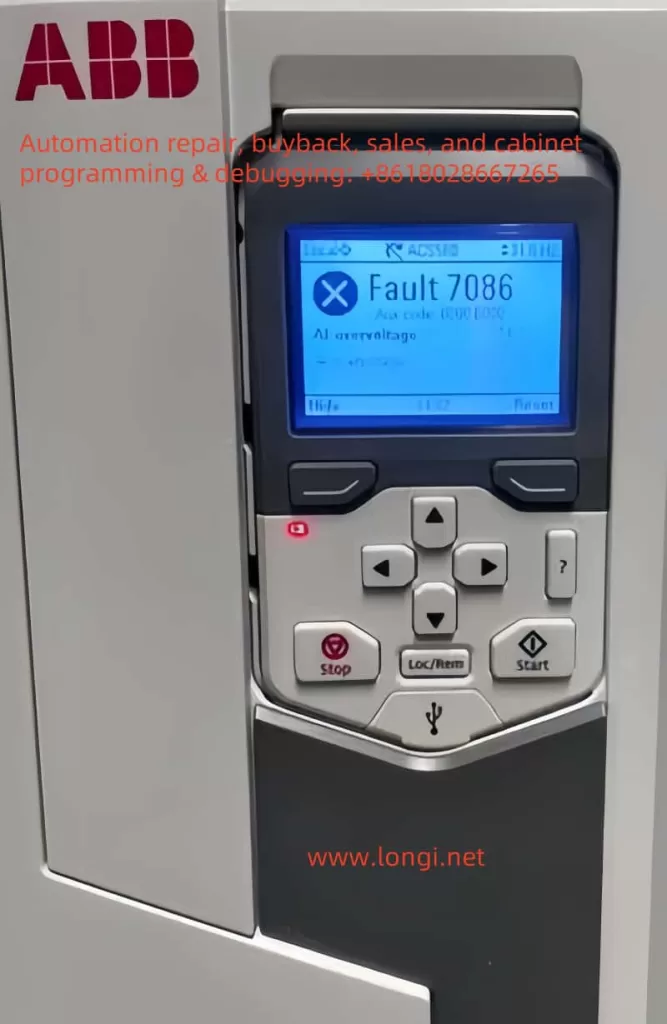
In the field of industrial automation, ABB’s ACS580 series inverter is widely used in various drive control scenarios due to its high efficiency and stable performance. However, during actual operation, the inverter may encounter faults for various reasons, among which FAULT 7086 is a relatively typical issue. This article will systematically analyze the handling strategies for this fault from the aspects of fault definition, causes, solutions, and preventive measures, providing comprehensive guidance for equipment maintenance personnel.
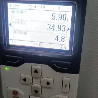
FAULT 7086 is officially defined as Analog Input Overvoltage (AI Overvoltage), which means the inverter detects that the voltage of the analog input (AI) signal exceeds the preset threshold. When this fault is triggered, the inverter will automatically switch the AI input mode from current mode to voltage mode to protect the circuit. After the signal returns to normal, the system can switch back manually or automatically.
From a design logic perspective, the AI input is a crucial interface for the inverter to receive external control signals (such as sensor data and setpoints). Its stability directly affects the control accuracy and system safety. When the input voltage rises abnormally, it may damage the internal circuit or cause control logic errors. Therefore, the inverter needs to issue an early warning through a fault code.
II. In-depth Analysis of Fault Causes
2.1 AI Signal Source Issues
Sensor Failure: Sensors for temperature, pressure, etc., may output abnormally high voltages due to aging or damage.
Signal Source Configuration Errors: For example, connecting a 0-10V output device to a 4-20mA input terminal, resulting in signal level mismatch.
2.2 Wiring and Interference Issues
Short Circuit in Wiring: Short circuits in AI signal lines or damage to connectors.
Electromagnetic Interference (EMI): Parallel routing of AI signal lines with high-power lines (such as motor cables and inverter output lines) without shielding measures.
2.3 External Device Failures
PLC or Controller Anomalies: Control devices may output error signals due to program errors or hardware failures.
Power Fluctuations: Unstable power supply to external devices, leading to signal level fluctuations.
2.4 Drive Internal Failures
AI Processing Circuit Damage: Aging components, lightning strikes, or operational errors causing circuit failure.
Firmware Version Defects: Old firmware versions may have vulnerabilities in AI input detection algorithms.
III. Fault Impact and Risk Assessment
3.1 Direct Impact on the Control System
Reduced Control Accuracy: AI input anomalies may cause deviations in setpoints such as speed and torque.
System Shutdown: If the fault is not cleared in time, the inverter may trigger protective shutdown.
3.2 Potential Risk Analysis
Equipment Damage: Prolonged overvoltage may burn out the AI input module or main control board.
Production Loss: Sudden shutdowns or control anomalies may halt production lines, resulting in economic losses.
IV. Systematic Solutions
4.1 Preliminary Diagnostic Process
Observe the Control Panel: Confirm whether fault code 7086 is accompanied by a red warning light.
Record Ax Code: If Ax code (00 000) is displayed, locate the specific channel with the manual.
4.2 Step-by-step Handling Strategies
4.2.1 Signal Source Inspection
Calibration Verification: Use a standard signal source to test the AI input channel and confirm detection accuracy.
Replacement Method for Troubleshooting: Temporarily replace sensors or signal lines to observe whether the fault transfers.
4.2.2 Wiring Optimization
Physical Isolation: Separate AI signal lines from high-power lines and add metal shielding.
Grounding Inspection: Ensure common grounding of the signal source, inverter, and control cabinet to reduce potential differences.
4.2.3 External Device Diagnostics
Signal Isolation: Add signal isolators between the PLC and inverter to block interference transmission.
Power Purification: Equip external devices with UPS or APF devices to eliminate power harmonics.
4.2.4 Drive System Handling
Firmware Upgrade: Update to the latest firmware version through Drive Composer tools.
Parameter Reset: Restore AI input parameters to factory settings and reconfigure them step-by-step.
4.3 Advanced Handling Techniques
Waveform Analysis: Use an oscilloscope to capture AI signal waveforms and identify transient interference or continuous overvoltage.
Temperature Monitoring: Check the internal temperature of the inverter to rule out circuit false alarms caused by overheating.
V. Preventive Maintenance Strategies
5.1 Regular Inspection Plan
Quarterly Inspections: Measure AI signal levels and verify sensor accuracy.
Annual Maintenance: Clean the inside of the control cabinet and inspect wiring aging.
5.2 Parameter Management Practices
Backup Configuration: Before modifying AI parameters, use Drive Composer to export the configuration file.
Version Control: Establish a firmware version ledger to track upgrade records.
5.3 Personnel Training Mechanisms
Skill Certification: Require maintenance personnel to pass ABB official training and master fault handling procedures.
Case Sharing: Establish a fault handling database and regularly analyze typical cases.
VI. Conclusion
Although FAULT 7086 involves multiple potential causes, the occurrence probability can be significantly reduced through systematic diagnostic procedures and preventive maintenance strategies. During actual handling, maintenance personnel should prioritize troubleshooting signal sources and wiring issues, utilizing oscilloscopes and other tools for in-depth analysis. Meanwhile, it is recommended that enterprises establish equipment health records and achieve predictive maintenance through data-driven approaches, thereby comprehensively enhancing the operational reliability of ACS580 series inverters. For complex faults, promptly contacting ABB technical support and leveraging the manufacturer’s professional resources can significantly shorten fault recovery time.
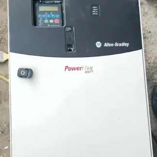
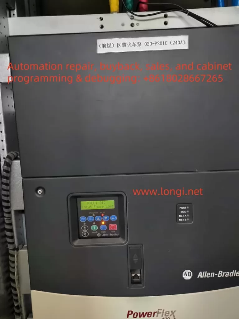
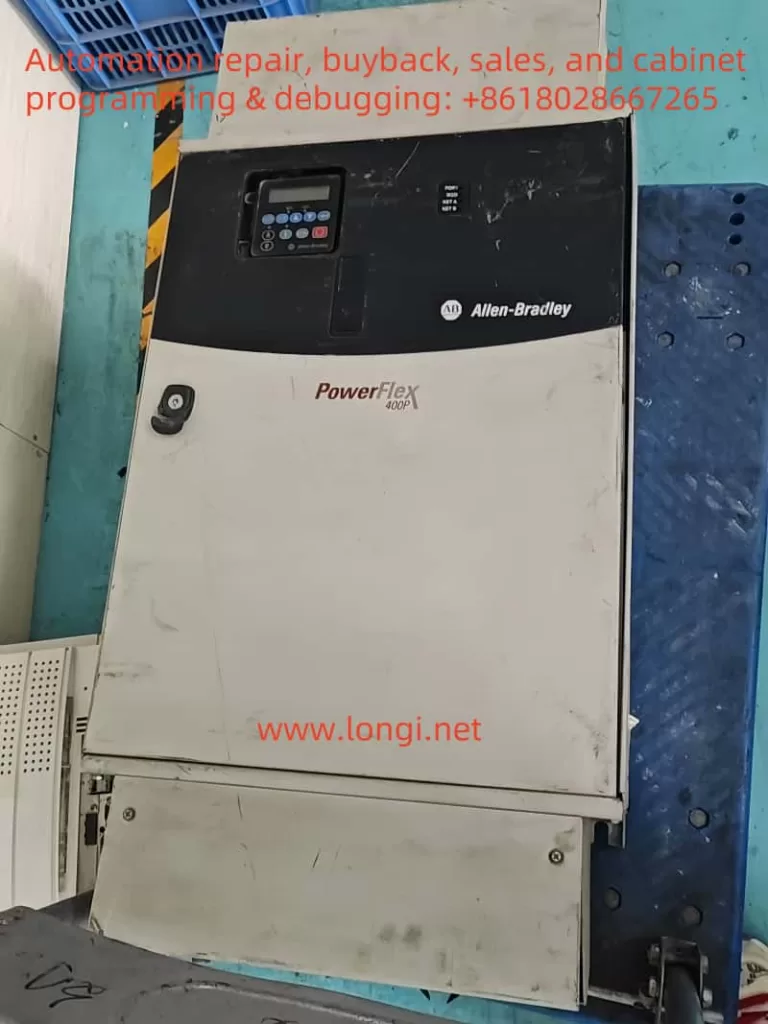
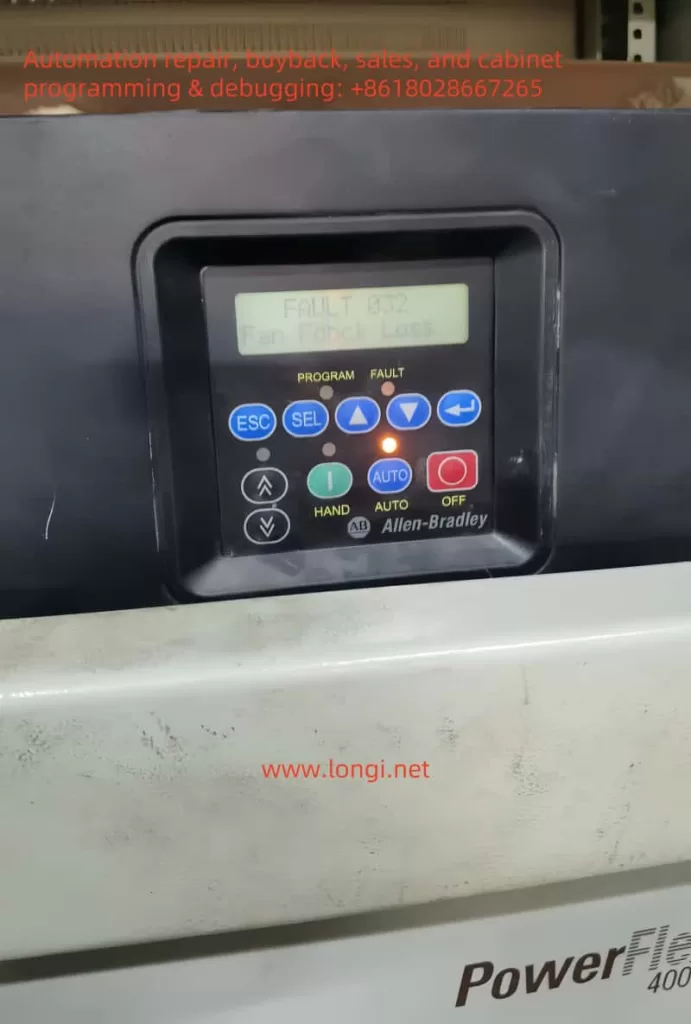
In modern industrial automation, variable frequency drives (VFDs) play a crucial role in adjusting motor speed, achieving energy savings, and providing precise control. Rockwell Automation’s PowerFlex 400 series, designed specifically for fan and pump applications, is known for its rich functionality and high stability. However, even the best drives can still encounter fault alarms in complex industrial settings. This article focuses on FAULT 017 (“Input Phase Loss”), commonly seen on the PowerFlex 400 series, offering an in-depth look at its implications and a clear, actionable approach to troubleshooting and remediation. With over a thousand words, it aims to provide practical, original guidance for readers.
Among the numerous fault codes of the PowerFlex 400, FAULT 017 (Input Phase Loss) often signifies a detected imbalance or loss of phase in the drive’s three-phase input power supply. In essence, the drive will trigger this alarm if one of the three-phase voltages is missing, or if the voltage imbalance exceeds the permissible threshold. Once triggered, the drive will shut down output to protect the power module—i.e., the rectifier, DC bus, and inverter section—from further damage.
From an application standpoint, fans and pumps commonly present large rotational inertia and high startup currents. If system voltage fluctuations are not well controlled, or if the power grid experiences significant swings, the drive is more likely to perceive an “input phase loss.” Furthermore, many users install fuses or circuit breakers upstream to protect the drive; a single blown fuse or faulty breaker contact in one phase can also cause this fault. Thus, FAULT 017 is not an isolated problem but rather a comprehensive alarm related to external power supply quality, the operational state of the load, and the health of the drive itself.
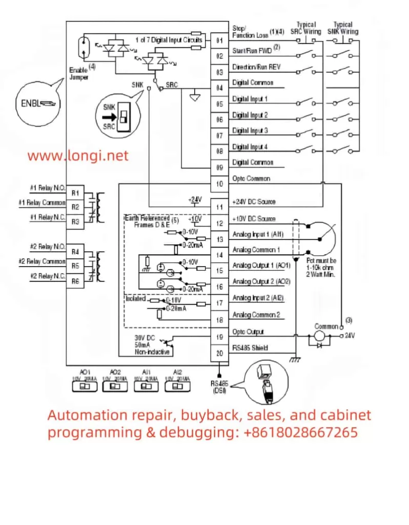
II. Causes and Underlying Principles
Line-Side Phase Loss or Severe Voltage Drop
In a three-phase circuit, if one fuse is blown, a circuit breaker trips on a single phase, or if a connection terminal is badly loosened, the drive might only receive two phases (or even one phase). Consequently, the rectifier section cannot create a balanced DC bus voltage, triggering the phase-loss alarm.
Large, sudden dips in voltage (caused by unexpected loading, inadequate transformer capacity, etc.) can also be interpreted by the drive as “lost input phase.”
Incorrect Fuse or Circuit Breaker Rating
If the chosen fuse/circuit breaker is undersized, or not matched to the nameplate specifications of the drive, the high inrush current when starting may cause one fuse to blow. Alternatively, continuous operation near or above rated limits can blow fuses in a single phase, leading to a phase loss alarm.
Defective Contactors or Loose Input Terminals
In industrial settings, loose terminal screws, oxidation, and contactor burn marks are quite common. These can cause abnormal current flow in one phase, resulting in voltage imbalance and triggering the alarm.
Malfunction of the Drive’s Internal Rectifier or Detection Circuit
Damage to the drive’s internal rectifier bridge, DC bus, or current detection modules—whether caused by overvoltage spikes or component aging—can lead the drive to incorrectly (or correctly) identify a phase loss. If external measurement confirms normal supply voltage, yet the fault persists, internal hardware failure is likely.
III. On-Site Troubleshooting Approach
Safe Shutdown and Visual Inspection
Always power off the system and wait at least three minutes before any inspection, giving sufficient time for internal high-voltage capacitors to discharge and ensuring safety. Check the drive’s cooling channels, enclosure, and cable terminals for signs of burn, overheating, or odor. If abnormalities are observed, the drive casing may need to be opened for a deeper inspection of internal components.
Measuring Three-Phase Input Voltage
Use a multimeter or clamp meter to measure voltages at R/L1, S/L2, T/L3 and check whether they are in the correct phase-to-phase range (normally ±10% of the drive rating). If one phase has no voltage or is significantly lower than the other two, focus on that line’s fuse, circuit breaker, or input terminal first.
Fuse and Circuit Breaker Checks
Reference the standard fuse or breaker sizing recommended in the drive manual to ensure proper matching. If a fuse is found to be blown or a breaker has tripped on one phase, replace it and investigate the cause (overload or short circuit).
Confirm the breaker has not partially tripped, leaving only two phases powered.
Inspection of Contactors and Terminal Tightness
In systems with contactor switching or star-delta transition, worn or pitted contacts can cause open-phase conditions. Examine all contacts with a meter to ensure they behave consistently.
Tighten all terminal screws on the drive input; vibration or temperature changes can loosen them over time.
Re-energize and Reset Fault
After external electrical issues are remedied, reapply power to the drive and see if the fault resets automatically or if a manual reset is required (consult the drive’s manual in Chapter 4, “Fault Handling”). If the fault remains, the drive may have an internal hardware failure.
IV. Root Cause Analysis and Countermeasures
Poor Power Supply Quality
Some plants have large loads starting or stopping simultaneously, causing dramatic voltage dips or fluctuations. Consider adding a line reactor or isolation transformer ahead of the drive to buffer against such interference. Where possible, upgrading network capacity or reducing high inrush loads can also mitigate phase-loss alarms.
Aging Components or Improper Ratings
If slow-blow fuses are unsuited for the motor startup characteristics, or if circuit breakers or contactors are poorly rated, single-phase fuse blowing and contact failures may occur frequently. In heavily used fan or pump systems, selecting protective devices properly rated for maximum operational current is crucial.
Site Vibration and High-Temperature Environments
Fans and pumps often operate in areas subject to vibration and temperature swings. Loose screws and increased contact resistance are common. Regular inspection schedules and using anti-vibration measures, such as thread-locking compounds on terminal screws, can improve connection reliability.
Internal Component Damage
Once external phase-loss causes are ruled out and the fault persists, open the casing to check for damage on the rectifier bridge, DC bus, or sensor board. Any burn marks, bulged capacitors, or cracked circuit traces may indicate the root failure. In such cases, a specialist or authorized service should handle repairs or replacements.
V. Fault Management and Maintenance Steps
Emergency Measures
If production needs to resume quickly after verifying balanced three-phase supply, attempt to reset or re-power the drive to see if the alarm disappears. This could indicate only a temporary fault.
If the fault cannot be cleared, temporarily switch the motor to run at line frequency (assuming the motor and process allow direct-on-line starts) to maintain production. Note that this bypasses the benefits of variable speed control, and starting current may spike significantly.
Long-Term Solutions
Following the guidelines in the drive manual (Sections 1-5, 1-6 on input power considerations), add a suitable line reactor or EMI filter to increase the drive’s immunity to supply disturbances.
If a fuse, breaker, or contactor is mismatched, replace or upgrade it per the drive’s power specifications.
Conduct regular inspections of both the drive and its upstream components. For demanding fan/pump environments, shorten the service interval accordingly.
Testing Hardware Components
If an internal failure is suspected, test the rectifier module or filter capacitors for short, open circuit, or performance degradation. Checking the driver board and DC bus voltage sensors thoroughly is advisable.
Replace damaged modules or send the drive for professional repair as needed. After repair, test the drive under no-load conditions, ensuring the fault does not recur, then reintroduce the motor load for final verification.
VI. Conclusion
PowerFlex 400 series drives are celebrated for their reliability and versatility, but under harsh or improperly maintained conditions, FAULT 017 (Input Phase Loss) may still occur. Essentially, this fault indicates a missing or unbalanced three-phase input supply. The root cause might be an external breaker or fuse issue, a loose terminal, or damage within the drive’s rectifier or detection circuitry. Operators should first confirm that the external supply is reliable and properly balanced, then troubleshoot and service drive components if necessary. Avoiding a hasty replacement of the drive without investigating the power system’s hidden risks is also key.
For routine maintenance and prevention, pay close attention to line cable connections, proper fuse ratings, and sudden system surges. When justified, install line reactors or EMI filters and maintain inspection logs. Only by thoroughly addressing the underlying causes can you reduce the frequency of FAULT 017, thereby extending the life of the drive and enhancing production efficiency.
In short, FAULT 017 is not merely a problem internal to the drive—it reflects a combined effect of input power and load conditions. Both short-term fixes and long-term measures require checking power supply, protective components, and the drive itself. A full understanding of the alarm’s meaning and trigger logic empowers you to tackle it effectively, ensuring stable operation of your PowerFlex 400 drive in complex industrial environments.
In the field of industrial automation, the PowerFlex 750 series drives by Rockwell Automation are highly regarded for their flexibility, scalability, and rich functionalities. However, precisely because these drives offer numerous optional modules and communication methods, certain fault messages can appear in ways that seem puzzling. Many engineers, for instance, encounter an alert such as “X06 Not Running” or “Port x06 Not Running,” only to open the drive’s enclosure and discover—much to their surprise—that there is no label or port physically marked “X6.” This article aims to address that very phenomenon by clarifying the relationship between logical ports and physical slots. We will delve into why the “X06 Not Running” error occurs, how to troubleshoot it systematically, and—given the possible scenario of drives connected in parallel—how to arrive at practical solutions.
In PowerFlex 750 series drives, the term “Port” represents not just a visible hardware interface, but a logical address assigned by the drive firmware. For example, Port 0 usually refers to the Main Control Board, Ports 1 and 2 might be for the front-panel Human Interface Module (HIM) or DPI devices, while Port 6 typically corresponds to the optional module slot, often labeled “Slot C” or “Option Slot 3.” When the drive reports “X06 Not Running” or “Port 6 Adapter Fault,” it is referring to logical Port 6, indicating a module at that position is malfunctioning, rather than some physical connector marked “X6.”
2. Physical Labels Often Appear as “Slot C” or “Option Slot 3”
From a design standpoint, to accommodate various expansion needs in a limited space, the main control board usually includes three to four optional module slots for installing communication adapters, I/O extension cards, or feedback modules. These slots are often labeled “Slot A/B/C” or “Option Slot 1/2/3.” At the software level, the drive maps these slots to Ports 4, 5, 6, and so forth. The main objective is to unify the management of internal and external resources: logical port numbering handles internal data flow, whereas hardware slot labels facilitate on-site module installation and removal.
Consequently, you may see a physical slot labeled “Slot C” or “Option 3” on the drive but not find any silkscreen or marking of “X6” or “Port 6.” If the module in this slot malfunctions or if the slot configuration is incorrect, the system will display an alarm specifically mentioning “Port 6,” leading to a mismatch between how the hardware is labeled and how the firmware identifies it.
II. Possible Causes of the “X06 Not Running” Error
When you see “X06 Not Running” or “Port 6 Not Running,” it generally indicates that the expansion module at Port 6 is in an abnormal state. Common causes include:
Uninstalled or Empty Slot, Yet Configured The drive might be configured to have a communication or I/O module at Port 6, but the slot is physically empty. Consequently, the system cannot detect the module and raises the error indicating that Port 6 is not running.
Improper Module Installation or Hardware Failure If the slot does have an expansion module (for example, a 20-750-ENETR Ethernet adapter or a 20-750-DNET DeviceNet adapter) but the module is loose, has poor contact, or is damaged, the drive will perceive it as disconnected. Hardware issues can include defective internal components, as well as firmware incompatibilities.
Network or Communication Configuration Conflicts For communication modules, if there is a duplicate network address, a mismatched baud rate, or a failure on the fieldbus (cabling short, bus power issues, and so on), the module cannot communicate properly with the drive’s main board. As a result, the drive may show “Port 6 Not Running” or “Comm Loss.”
Firmware and Configuration Incompatibility When the drive’s firmware version differs substantially from that of the module, the drive might not be able to fully recognize the module’s functionality or might detect an invalid configuration. An older drive firmware may not support certain features in a new adapter.
Parallel System Configuration Errors In systems where multiple PowerFlex 750 drives are connected in parallel to drive a high-power motor or share a common bus, Port 6 is often used for inter-drive synchronization or redundancy communication. An addressing conflict or a misconfiguration of master/slave roles can cause one of the drives to report a port error.
III. Why You Can’t Find “X6” After Disassembling the Drive
Many users, upon seeing the fault code, first attempt a physical inspection. However, after opening the enclosure, they notice that none of the slot labels match “Port 6,” and they don’t see anything labeled “X6.” This is likely due to the following factors:
Chassis Labels Only Read “Slot C” The PowerFlex series generally uses letters or numbers to identify slot order, and not a marking such as “X6” or “Port 6.”
Ports Are Assigned at the Software Level Port 6, Port 5, Port 4, etc., are naming conventions in the drive’s internal DPI or system bus rather than user-facing hardware markings.
Slot Position May Be Obscured by a Metal Bracket or Circuit Board On higher frame sizes (Frame 8 and above) or particular designs, there may be layered sub-boards or shielding that hides the slot labels. You might need to remove additional parts to locate “Slot C.”
Empty or Damaged Slots If the slot meant for Port 6 is truly empty or if the module has fallen out or is damaged, there is no direct label for the user to see.
IV. How to Identify and Locate Port 6
Refer to the Official Installation Manual’s “Slot Layout Diagram” Rockwell documentation typically provides a layout diagram for these optional slots, clearly explaining how “Slot A = Port 4,” “Slot B = Port 5,” “Slot C = Port 6.” Comparing the manual’s diagram with the physical drive helps pinpoint the slot corresponding to Port 6.
Check Module Information Using HIM or Software By accessing the parameters in the front-panel HIM or by using DriveTools or Studio 5000 software, you can view “Module Info” or “Adapter Info,” where each port’s installed hardware is displayed. If Port 6 shows a communication adapter model, that indicates it is mounted in “Slot C” or “Option Slot 3” physically.
Physical Observation of the Slot Layout Most PowerFlex 753/755 drives have three side-by-side optional slots on or near the main control board, labeled A, B, and C, or Option 1, 2, and 3. If you see a module in Slot C, that module is the physical carrier for Port 6 from the firmware’s perspective.
Cross-Check with the Drive’s Fault Log The HIM or the drive configuration software can display a fault queue. If there are repeated references to “Port 6 Adapter Fault” or “Port 6 Comm Loss,” that indicates issues specifically related to the module in Slot C.
V. Steps to Resolve the “X06 Not Running” Error
Confirm Whether Port 6 Module Is Needed
If the slot is supposed to be empty, disable or remove the configuration referencing Port 6 in the drive parameters.
If it does require a module, check whether the module is missing or physically damaged.
Examine Physical Installation and Connections
Power down the drive, remove the module, inspect for bent pins or contamination, then re-seat it firmly.
For communication modules, make sure the bus cables and terminators are set up properly, and that bus power is available.
Diagnose Network Conflicts
For DeviceNet or other fieldbus protocols, ensure all device addresses are unique and the baud rate matches.
In parallel systems, verify that each drive’s address and roles (master/slave) do not conflict.
Check Drive and Module Firmware Compatibility
Certain older drives might not recognize newer modules. Consult the official Rockwell documentation and release notes, and consider firmware updates that support the required module features.
Factory Reset or Reconfigure If Necessary
If hardware is intact but the issue persists, try restoring Port 6 parameters to defaults and then reapply correct settings. This step can help resolve initialization failures caused by parameter corruption.
VI. Avoiding Port Faults in Parallel Applications
When multiple PowerFlex 750 drives run in parallel to drive a high-power motor or share a common bus, they often rely on inter-drive communication and synchronization. Common issues leading to “X06 Not Running” in such scenarios include:
Address Conflicts: For instance, if each drive has a DeviceNet module with the same node address, then some modules will drop offline.
Improper N-1 Redundancy Configuration: If one drive is designated as the master and another is the follower, a misconfigured follower may cause the master drive to detect that Port 6 is down, stopping the entire system.
Missing Synchronization Signals: If the optical fiber or sync cables between parallel drives are disconnected, the drive can report a fault for the relevant port.
To prevent such faults, proper planning is essential from the outset—assigning unique addresses, defining consistent master/slave roles, and thoroughly testing each drive individually, then in collective operation. Regularly monitoring network status and each drive’s port modules will help you detect potential problems early.
VII. Conclusion
The message “X06 Not Running” may initially seem mysterious or perplexing, but in reality, it reflects the PowerFlex 750 drive’s internal scheme for managing expansion modules via logical ports. The drive firmware assigns port numbers to identify each module; as soon as a particular module is missing, malfunctioning, or misconfigured, the drive displays an alert naming that logical port—for example, Port 6. Effective troubleshooting requires a solid understanding of how hardware slots (such as Slot C) correspond to these logical ports, along with targeted use of official documentation or diagnostic tools. In multi-drive, parallel systems, you must also pay close attention to address settings, role assignments, and synchronization signals to ensure each drive operates in harmony. By applying the concepts outlined here, you can significantly reduce downtime and confusion related to “X06 Not Running” or similarly cryptic errors. This knowledge also lays a robust foundation for future maintenance and potential system expansions, where familiarity with port-slot logic and network coordination becomes even more valuable.
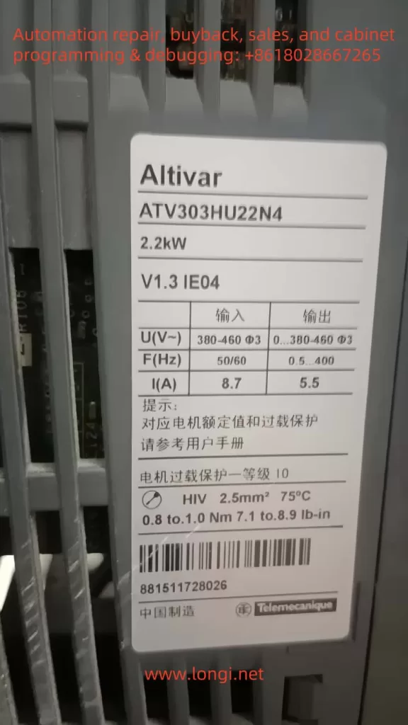
Within the realm of industrial automation, frequency inverters have become indispensable for motor control. Schneider Electric’s ATV series inverters enjoy a strong reputation for reliability and versatility, making them popular in many factories and engineering projects. The ATV303, in particular, is a cost-effective model frequently used with fans, pumps, and conveyor systems. For maintenance personnel, a solid understanding of the inverter’s fault and status codes is crucial for improving production efficiency, reducing downtime, and preventing unnecessary equipment damage.
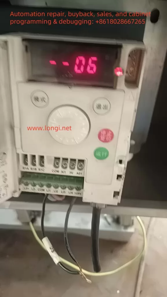
In actual usage, one may occasionally see the code “06” appear on the display panel of the ATV303 inverter. Since most real faults are labeled with an “F” prefix (e.g., F013 for motor overload or F011 for an overheat warning), many technicians might feel confused upon seeing “06”: Is it a fault code or just a normal state indicator? Is urgent shutdown and troubleshooting needed? In fact, the “06” code on the ATV303 is not a fault, but rather an indication of the Freewheel Stop state. This article provides a detailed explanation of the meaning of the “06” code, why it might appear, and how to deal with it properly so that readers can swiftly diagnose and address the situation.
II. The Real Meaning of Code 06
According to the official Schneider documentation for the ATV303, any code beginning with an “F” denotes an actual fault alarm—examples include F002, F006, F013, and so on. These alarms necessitate analysis of potential hardware or configuration issues, followed by the relevant reset or maintenance actions. In contrast, code “06” is explicitly categorized as a product status indicator. Rather than a hardware failure or system anomaly, it indicates a specific operational condition.
The “06” code stands for Freewheel Stop. In practical terms, freewheel stop means that the inverter is no longer supplying torque to the motor, allowing the motor shaft to come to rest solely through its own inertia. It differs from controlled or braked stopping methods: no active deceleration curve is applied, nor does the inverter inject direct current (DC) into the motor for braking. The time it takes the motor to stop primarily depends on load inertia.
Since the “06” state is not a failure, operators need not fear equipment damage or software errors. However, understanding why an inverter enters freewheel stop remains crucial. If “06” is triggered unexpectedly, it may disrupt normal operations or break the production rhythm. Only by identifying and addressing whatever caused the inverter to enter freewheel stop can the system resume normal operation.
III. Common Triggering Causes
Activation of a Logic Input The inverter’s logic inputs (e.g., LI1, LI2) can each be assigned custom functions. One of those functions is often “Freewheel Stop.” If a digital input is configured this way and happens to be energized—for instance, an external emergency stop circuit or sensor being triggered—then the ATV303 will automatically switch to freewheel stop and display “06.”
Selected Control Method In two-wire control setups (i.e., one input for Run/Stop), the inverter waits for a valid Run signal after power-up. If that signal is absent or the wiring logic dictates a stop condition, the inverter might remain in freewheel stop. In some designs, the user must explicitly toggle the Run input once the inverter is powered up before it can exit “06.”
Local/Remote Switching When the inverter is in remote-control mode, pressing the local STOP button or encountering a communication loss may force the inverter into freewheel stop. In these scenarios, code “06” will remain until a valid remote Run command is received again or communication is restored.
PID or Other Functional Settings If the inverter is configured for closed-loop PID control and the feedback signal is lost—or the user deliberately set a “freewheel stop on signal loss” strategy—the inverter will carry out that plan by showing “06.” Once the signal is restored or a different stopping approach is chosen, the operator must send a new Run command to exit freewheel stop.
IV. Handling Approach and Detailed Operation
Check the Logic Input Configuration If you suspect a particular digital input is assigned to freewheel stop, inspect the assignment in the inverter’s configuration menu (COnF). Should you find that an input is set for FSt (Freewheel Stop) and it is in an active state (e.g., turned on), you can disable this input or remove its power signal to release the inverter from freewheel stop, returning it to a ready state.
Examine Emergency Stop or Safety Circuits In many systems, an emergency stop circuit signals the inverter via a digital input or relay contact for freewheel stop. If an emergency stop is pressed, “06” will appear until you physically reset that emergency circuit. Ensure that no unsafe conditions remain in the machinery before re-engaging the e-stop circuit and clearing the “06” state.
Resend Run Command in a Two-Wire Control Setup In a two-wire control scheme, you often need to remove and then reapply the Run signal after power-up. Without this, the inverter stays in freewheel stop mode. Once you provide the correct Run input, the inverter leaves “06” and begins outputting to the motor.
Use a Start Button in a Three-Wire Setup If the system is wired for three-wire control (separate Start and Stop buttons), the inverter expects a start pulse after the stop button is released. Simply pressing the start button again should cause the display to switch from “06” to normal operation.
Check Communication Settings In scenarios where the inverter is governed by serial communication from a PLC or computer, the absence of a valid run command or a temporary communication fault can lead to freewheel stop. Verify that the communication settings (baud rate, parity, data bits) match, and confirm the controller has issued the correct commands to restore normal drive operation.
Avoid Signal Loss For advanced setups where the inverter is configured to freewheel stop upon losing an analog input (e.g., 4–20 mA), make sure sensors and cables are secure. Restoring the signal or adjusting the signal-loss strategy can eliminate “06.” Then, simply sending a valid run command should re-energize the motor.
V. Distinctions from Real Faults and Prevention
Unlike a code starting with “F,” which denotes actual faults requiring reset or more in-depth troubleshooting, “06” merely reflects the inverter’s execution of a normal freewheel stopping command. The user does not need to perform hardware inspections or a dedicated fault reset. However, an unintended or extended freewheel stop could disrupt production. Hence, it is crucial to configure your control logic carefully and secure all wiring to avoid unplanned “06” occurrences. Where higher safety requirements exist, you may prefer an alternative form of stopping such as fast ramp stop or DC injection, based on the demands of your process.
VI. Conclusion
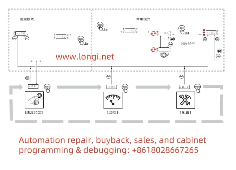
To summarize, code “06” on the Schneider ATV303 inverter is not a sign of component malfunction. Instead, it indicates that the inverter is currently in Freewheel Stop mode—no torque or braking is being applied to the motor, so the load is free to coast to a standstill under its own inertia. Restoring normal operation involves determining the specific reason for freewheel stop—whether it’s a digital input function, an emergency stop condition, a missing run command, or a lost feedback signal. Once you remove or correct that cause, the inverter will automatically revert to a ready state (–00) or re-engage in normal operation if a run command is still active.
For real-world projects, ensuring your ATV303 is configured correctly—and that all external wiring and control signals are stable—will go a long way toward preventing unwanted freewheel stops from interrupting production. By grasping the function and handling of the “06” status, maintenance personnel can promptly troubleshoot and restore equipment to service, minimizing downtime and optimizing operational safety.
By understanding the meaning and responses associated with “06,” operators and technicians can effectively manage a common inverter behavior without confusion. Adhering to official Schneider documentation and combining that guidance with the specific control requirements of your system will ensure that the freewheel stop state works for you, rather than against you, in all industrial automation scenarios.
The Rockwell (Allen-Bradley) PowerFlex 400 series inverter is a powerful industrial control device designed for applications such as fans and pumps, offering flexibility, ease of configuration, and high reliability. This article, based on the PowerFlex 400 series manual, provides a detailed guide on its operation panel functions, external terminal control methods, and fault code troubleshooting. It aims to help users fully grasp the skills needed for operating and maintaining the equipment. This guide is clear, logical, and comprehensive, suitable for engineers, technicians, and field operators.
The PowerFlex 400 series inverter is equipped with a user-friendly Human Interface Module (HIM), which allows parameter configuration, status monitoring, and fault diagnosis via buttons and a display screen. Below is a detailed explanation of its main functions and operation steps.
1. Panel Layout and Button Functions
The operation panel is the core interface for user interaction with the inverter. Its layout includes:
LCD Display: Shows running frequency, parameter numbers, fault codes, etc.
Arrow Keys (Up, Down, Left, Right): For menu navigation and parameter adjustment.
Enter Key: Confirms selections or saves settings.
Esc Key: Returns to the previous menu or cancels operations.
Start/Stop Keys: Starts or stops the inverter in manual mode (must be enabled via parameters).
Familiarity with these buttons allows users to easily navigate menus and complete configurations.
2. Copying Parameters to Another Inverter
The PowerFlex 400 supports parameter copying, making it easy to replicate settings across multiple devices. Follow these steps:
Step 1: On the source inverter’s HIM panel, enter the “Parameter” menu.
Step 2: Select “Copy to HIM” to save parameters to the panel’s memory.
Step 3: Remove the HIM panel from the source inverter and insert it into the target inverter.
Step 4: On the target inverter, enter the “Parameter” menu and select “Copy from HIM.”
Step 5: Confirm to load the parameters onto the target inverter.
Note: Both inverters must be of the same model and firmware version to avoid compatibility issues.
3. Initializing Parameter Settings
To reset the inverter to factory settings, follow these steps:
Step 1: Enter the “Parameter” menu and locate parameter P041 (Reset to Defaults).
Step 2: Set P041 to “1” (Reset) and press Enter to confirm.
Step 3: Wait for the inverter to complete the reset; the display will indicate success.
Note: Initialization erases all user settings; it is recommended to back up parameters first.
4. Setting Password and Parameter Access Restrictions
To protect parameters from unauthorized changes, the PowerFlex 400 offers a password feature:
Step 1: Enter the “Parameter” menu and find parameter P042 (Password).
Step 2: Enter a four-digit password (e.g., “1234”) and press Enter to save.
Step 3: Set parameter P043 (Password Enable) to “1” to activate password protection.
Step 4: In parameter P044 (Access Level), select the access level:
“0”: Basic (limited to common parameters).
“1”: Advanced (access to all parameters).
Note: If the password is forgotten, contact technical support or use specialized tools to unlock it.
II. External Terminal Control and Speed Regulation
The PowerFlex 400 supports forward/reverse control and frequency adjustment via external terminals, ideal for scenarios requiring manual switches or potentiometer control. Below are the wiring and parameter configuration methods.
1. External Terminal Forward/Reverse Control
To control start, stop, and direction via external switches, follow this wiring and setup:
Wiring Instructions:
Terminal 11 (Digital In 1): Connect to one end of the start/stop switch.
Terminal 12 (Digital In 2): Connect to the direction selection switch (forward/reverse).
Terminal 01 (Common): Common terminal, connect to the other end of the switches.
Parameter Settings:
P036 (Start Source): Set to “2” (2-Wire Control) to enable two-wire control mode.
P037 (Stop Mode): Set to “1” (Ramp) for smooth stopping.
A051 (Digital In1 Sel): Set to “4” (Run) to define terminal 11 as run control.
A052 (Digital In2 Sel): Set to “6” (Direction) to define terminal 12 as direction control.
Operation Verification: Close terminal 11 to start the inverter; switch terminal 12 to control direction.
2. External Potentiometer for Frequency Control
To adjust the operating frequency with an external potentiometer, follow this wiring and configuration:
Wiring Instructions:
Terminal 15 (Analog In 1+): Connect to the potentiometer’s wiper (signal output).
Terminal 16 (Analog In 1-): Connect to the potentiometer’s low potential end.
Terminal 17 (Analog In Common): Connect to the potentiometer’s high potential end (usually 10V supply).
Parameter Settings:
P038 (Speed Reference): Set to “2” (Analog In 1) to select analog input 1 as the frequency reference.
A065 (Analog In 1 Hi): Set to the maximum frequency (e.g., 60 Hz), corresponding to the potentiometer’s maximum.
A066 (Analog In 1 Lo): Set to the minimum frequency (e.g., 0 Hz), corresponding to the potentiometer’s minimum.
Operation Verification: Rotate the potentiometer to observe smooth frequency changes from minimum to maximum.
With these configurations, users can achieve external switch control for start/stop and direction, while precisely adjusting speed with a potentiometer.
III. Fault Codes and Their Handling
The PowerFlex 400 may trigger faults due to power, load, or environmental issues. Understanding fault codes and their solutions is crucial. Below are common fault codes, their meanings, and troubleshooting steps.
1. Common Fault Codes and Meanings
F005 (OverVoltage)
Meaning: DC bus voltage exceeds the allowable range, often due to rapid deceleration or power fluctuations.
Solution:
Check if the input power voltage is too high.
Extend the deceleration time in parameter P039 (Decel Time).
If frequent, consider installing a braking resistor.
F012 (UnderVoltage)
Meaning: DC bus voltage is below normal, possibly due to power interruption or poor wiring.
Solution:
Ensure the input power is stable and within the rated range.
Check for loose power connections.
F032 (Fan Feedback Loss)
Meaning: Cooling fan is not working or feedback signal is abnormal.
Solution:
Check for foreign objects blocking the fan.
Ensure the fan power cable is properly connected.
Replace the fan if damaged.
F048 (Params Defaulted)
Meaning: Parameters have been reset to factory defaults.
Solution: Reconfigure necessary parameters; consider backing up settings.
F081 (Comm Loss)
Meaning: Communication with the host or network is lost.
Solution:
Check communication cables and connectors.
Verify parameter A103 (Comm Format) is set correctly.
2. General Fault Handling Steps
Step 1: Record the fault code and operating conditions at the time.
Step 2: Refer to the manual’s fault code table to analyze possible causes.
Step 3: Check power, wiring, and load conditions to rule out external factors.
Step 4: Press the “Fault Reset” button to attempt a reset; resume operation if successful.
Step 5: If the fault recurs, contact Rockwell technical support for further assistance.
Conclusion
The Rockwell PowerFlex 400 series inverter, with its outstanding performance and flexible operation, is a preferred choice in industrial settings. This article covers the operation panel functions, external terminal control, and fault code handling, providing a comprehensive user guide. By mastering panel operations, users can efficiently configure parameters; through external terminal setups, they can achieve flexible control schemes; and with fault code analysis, they can quickly resolve issues to ensure stable operation. This guide aims to offer practical support, enhancing users’ efficiency and maintenance capabilities with the equipment.