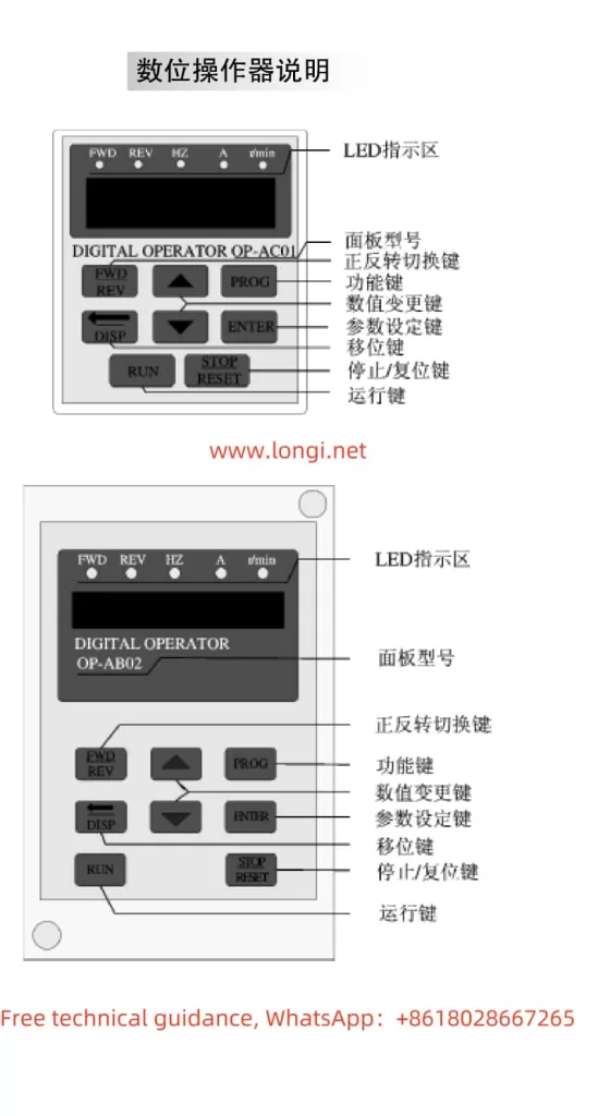
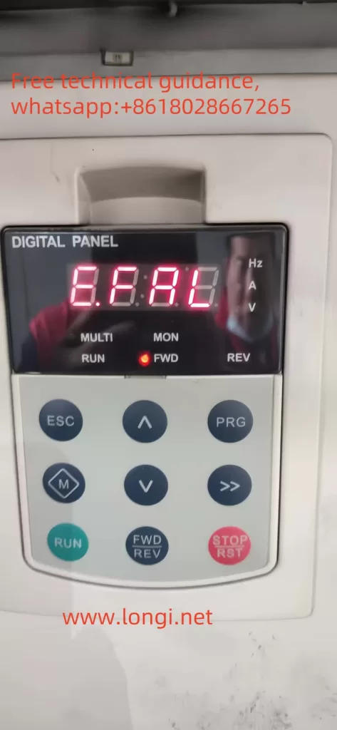
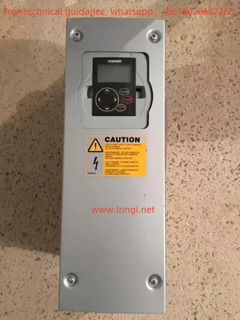
I. Introduction to the Operating Panel Functions
The Vacon NXS_NXP series inverters are equipped with an intuitive and user-friendly operating panel, providing users with a convenient interface for operation and monitoring. The operating panel typically includes a display screen, multiple function buttons, and status indicators. The display screen is used to show the current operating status, parameter values, and fault information. The function buttons are used for navigating menus, modifying parameter values, resetting faults, and other operations. The status indicators display the running status of the inverter, such as running, stopped, alarming, and faulting.
II. How to Initialize Parameters (Specific Parameters)
Before using the Vacon NXS_NXP series inverters, users may need to initialize the parameters to ensure all settings are at their default values. The initialization process usually includes restoring the factory settings of the inverter. Users can follow these steps to initialize the parameters:
- Enter the System Menu: First, access the system menu (usually labeled as M6) through the operating panel.
- Select Parameter Sets: In the system menu, find the parameter set option (typically labeled as S6.3.1).
- Restore Factory Defaults: In the parameter set option, select the “Load Factory Defaults” option and confirm the execution. This will restore all parameters of the inverter to their factory settings.
III. How to Set and Reset Passwords (Specific Parameters)
To protect the settings of the inverter from unauthorized changes, the Vacon NXS_NXP series inverters provide a password protection feature. Users can follow these steps to set and reset passwords:
- Setting a Password:
- Enter the system menu (M6).
- Find the password setting option (usually labeled as S6.5.1).
- Enter the password value (typically ranging from 1 to 65535) through the buttons on the operating panel.
- Confirm the password setting.
- Resetting a Password:
- Enter the system menu (M6).
- Find the password setting option (S6.5.1).
- Enter the current password (if already set).
- Set the password value to 0 and confirm the execution. This will disable the password protection feature.
IV. How to Set Parameter Access Restrictions (Specific Parameters and Operations)
In addition to password protection, the Vacon NXS_NXP series inverters also provide a parameter access restriction feature, allowing users to restrict access and modification of specific parameters. Users can follow these steps to set parameter access restrictions:
- Enter the System Menu (M6).
- Find the Parameter Lock Option (usually labeled as S6.5.2).
- Enable Parameter Lock: Set the parameter lock option to “Locked” and confirm the execution. This will restrict access and modification of most parameters.
- Disable Parameter Lock: When needing to modify locked parameters, first set the parameter lock option to “Unlocked” and confirm the execution.
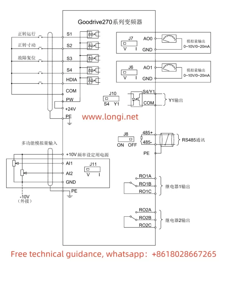
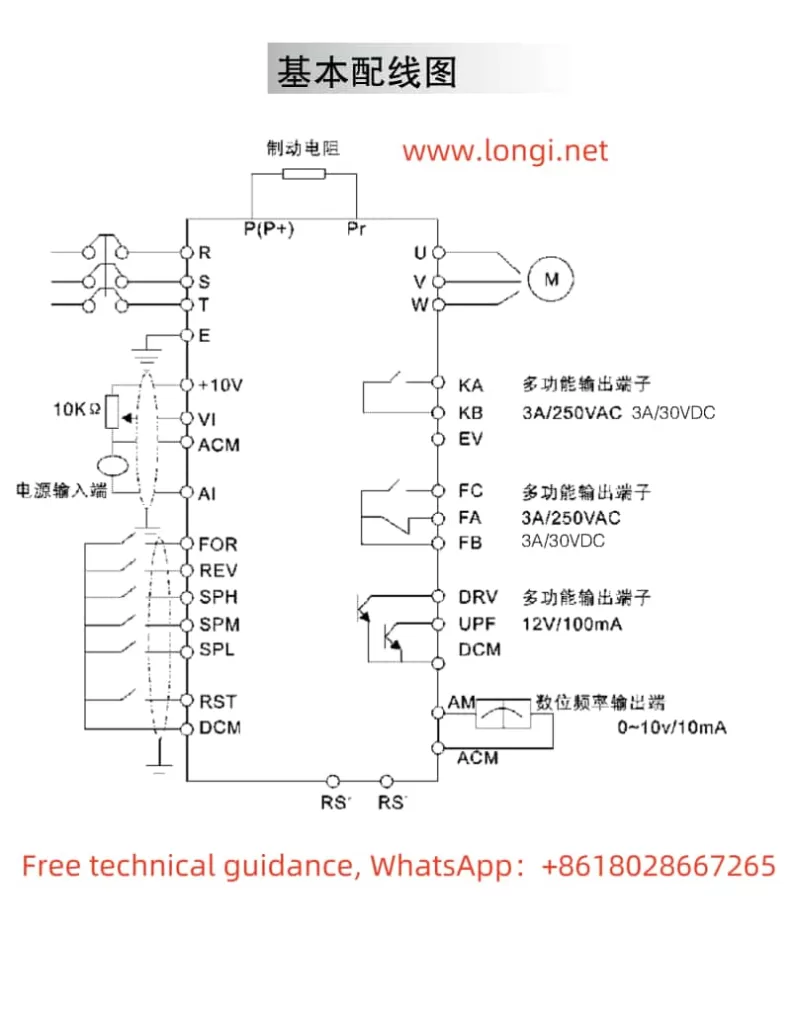
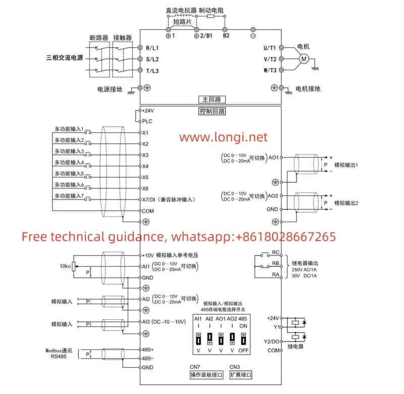
V. How to Achieve External Terminal Forward/Reverse Control and External Potentiometer Speed Regulation
The Vacon NXS_NXP series inverters support motor forward/reverse control through external terminals and speed regulation through external potentiometers. Users need to set the following parameters and connect corresponding terminals:
- Forward/Reverse Control:
- Parameter Settings: No specific parameter settings are required, but ensure the control signal source is set to external terminal control (P3.1=1).
- Wiring: Connect the external forward button or switch to DIN1 (or the designated forward input terminal), and connect the external reverse button or switch to DIN2 (or the designated reverse input terminal).
- External Potentiometer Speed Regulation:
- Parameter Settings: Ensure AI1 (or the designated analog input terminal) is set to accept analog voltage or current signals (specific settings depend on the potentiometer type).
- Wiring: Connect the output end of the potentiometer to AI1 (or the designated analog input terminal), and connect the common terminal of the potentiometer to AI1- (or the corresponding common terminal).
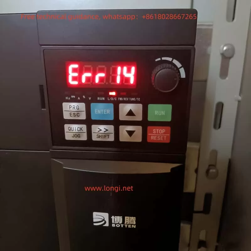
VI. Fault Codes and Their Solutions
The Vacon NXS_NXP series inverters feature comprehensive fault diagnosis capabilities. When a fault is detected, the inverter will display the corresponding fault code and fault information. The following are some common fault codes, their meanings, and solutions:
- Fault Code F01: Overcurrent
- Meaning: Motor current exceeds the rated value.
- Solution: Check if the motor load is too heavy, and check for short circuits or grounding in the motor and cables.
- Fault Code F02: Overvoltage
- Meaning: DC bus voltage is too high.
- Solution: Check if the power supply voltage is too high, extend the deceleration time, or increase the braking resistor.
- Fault Code F03: Ground Fault
- Meaning: Motor or cable grounding.
- Solution: Check the insulation resistance of the motor and cables.
- Fault Code F05: Charging Switch Fault
- Meaning: Charging switch failure.
- Solution: Check the charging switch and its connection lines, and replace the charging switch if necessary.
(Note: The above are only examples of some fault codes. For a complete list of fault codes and solutions, please refer to the inverter user manual.)
Through this guide, we hope to help users better understand and use the Vacon NXS_NXP series inverter user manual, achieving efficient and safe frequency control.