Introduction: The “Safety Red Line” in Inverter Protection
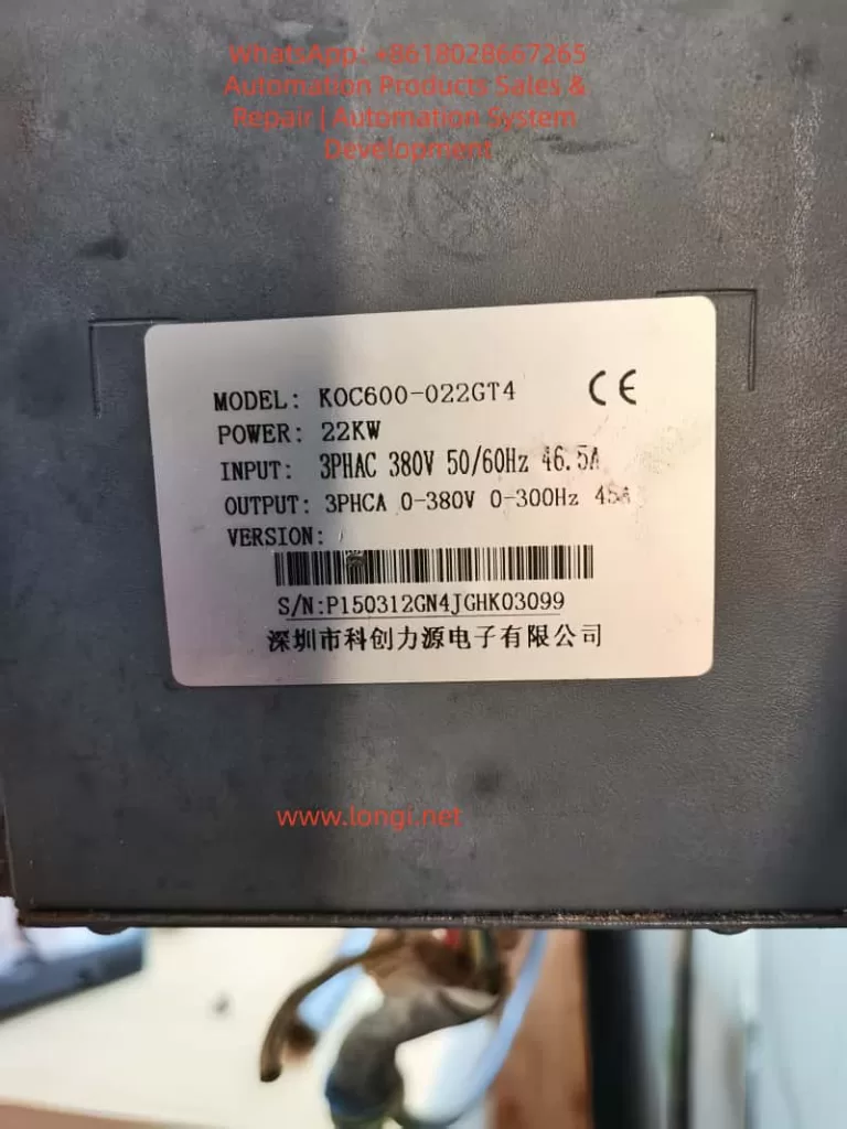
In modern industrial automation, the inverter is the heart of the motor drive system, and its stability directly impacts production efficiency. The KOC600 Series High-Performance Vector Inverter by Shenzhen Kechuan Liyuan (KCLY) is widely recognized for its precision and robust protection features.
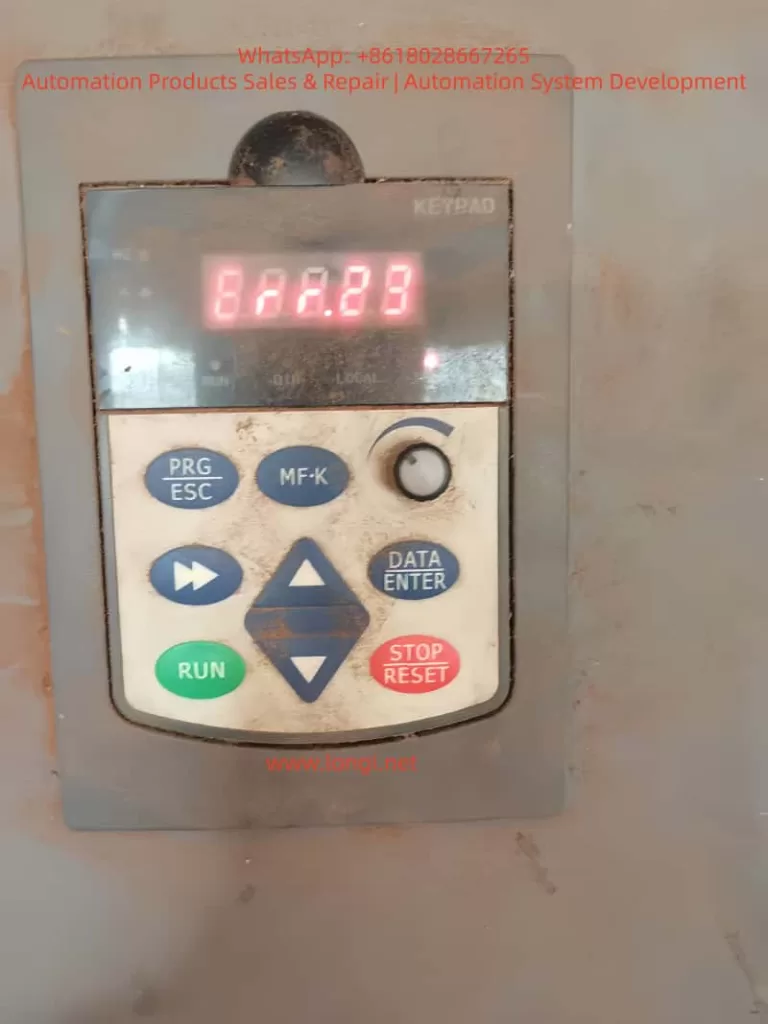
However, maintenance engineers occasionally encounter the Err.23 (Output to Ground Short Circuit) fault. A particularly puzzling scenario is when the inverter starts normally but suddenly trips with Err.23 after running for a period. This “dynamic fault” tests a technician’s diagnostic skills and threatens production continuity. This article provides a deep dive into the mechanisms, diagnostics, and solutions for Err.23 based on the KOC600 logic.
Chapter 1: Understanding Err.23 – The Technical Logic
1.1 What is an Output to Ground Short Circuit?
According to the KOC600 manual, Err.23 occurs when an unintended current path forms between the inverter’s output terminals (U, V, W) and the Ground (PE).
In a healthy state, the three-phase output currents are balanced; their vector sum should be near zero ($\vec{I_u} + \vec{I_v} + \vec{I_w} \approx 0$). If a phase leaks to the ground, this balance is broken. Internal Hall-effect current sensors detect this residual current. If it exceeds the safety threshold, the drive immediately blocks PWM output and triggers Err.23 to protect the internal IGBT power modules from destruction.
Chapter 2: Why Does it Fail After “Running for a While”?
When a fault occurs after minutes or hours of operation rather than at startup, it suggests a “dynamic” issue rather than a hard short circuit.
2.1 Heat-Induced Insulation Degradation
This is the most common cause. As the motor windings or cables heat up during operation:
- Mechanism: Micro-cracks in insulation may hold under cold conditions. As temperatures rise, materials expand or moisture evaporates into high-pressure pockets, causing the insulation resistance to drop momentarily and creating a flashover to the ground.
- Symptoms: The fault occurs once the motor reaches its rated load or thermal equilibrium.
2.2 Cumulative Leakage from Cable Capacitance
- Mechanism: Inverters output high-frequency PWM waves. Long cables act as capacitors between the conductors and the earth.
- Formula: $I = C \cdot \frac{dv}{dt}$.As operation continues, if humidity changes or the carrier frequency is set too high, high-frequency leakage current hits the protection circuit. At certain frequency points, resonance may cause the current peak to exceed the Err.23 threshold.
2.3 Environmental Factors: Condensation and Dust
In humid environments, temperature differences can cause condensation inside the motor terminal box. Initially, the system runs fine, but as moisture accumulates or mixes with conductive dust, it eventually creates a path to the chassis.
Chapter 3: The “Five-Step” Field Diagnostic Procedure
Step 1: Check Fault Scene Data (bC Parameter Group)
The KOC600 records vital data at the moment of failure. Before resetting, check the bC Group:
- bC-03: Output Frequency at fault.
- bC-04: Output Current at fault. Check if an overload accompanied the short.
- bC-05: Bus Voltage at fault. Fluctuations here can sometimes cause sensor errors.
Step 2: Decoupling Test (Disconnecting Motor Leads)
- Action: Remove all wires from the U/V/W terminals of the inverter.
- Conclusion:
- Still Err.23: Internal hardware damage (IGBT failure or sensor drift).
- No Error: The inverter is healthy; the fault lies in the cables or motor.
Step 3: Static Insulation Testing (Megger Test)
- Action: Use a 500V Megohmmeter to measure motor windings to ground.
- Standard: For a 380V motor, resistance should be > 5MΩ.
- Warning: Always disconnect the cables from the inverter before using a Megger, or you will destroy the drive’s power modules.
Step 4: Inspect Terminal Box and Cables
Check the motor terminal box for signs of moisture, carbonization (black marks), or loose screws touching the casing. Inspect the cable run for jacket wear, especially in conduits that may hold water.
Chapter 4: Advanced Optimization for KOC600
If no hard short is found, parameter tuning can often resolve nuisance trips caused by leakage or interference.
4.1 Adjust Carrier Frequency (Parameter b0-11)
Higher carrier frequencies increase ground leakage current.
- Optimization: Decrease the carrier frequency.
- Effect: This reduces the charging/discharging current of the cable capacitance, often eliminating “ghost” Err.23 reports.
4.2 Installation of Hardware Suppressors
For cable runs exceeding 50 meters:
- Output Reactor: Installed between the drive and motor to smooth the $dv/dt$ and suppress leakage.
- Zero-sequence Reactor (Ferrite Core): Looping the three output phases through a ferrite core to suppress high-frequency common-mode current.
Conclusion
Err.23 is a vital protective feature of the KOC600. When facing a fault that only appears after running for some time, technicians should apply a logical loop of Data Analysis -> Decoupling -> Insulation Testing -> Parameter Tuning.
Always prioritize safety: ensure the CHARGE lamp is completely off before touching any terminals. Proper maintenance and environmental control are the best defenses against “running-time” faults.