Table of Contents
- Introduction
- Basic Concept of AL-09 Overload Fault 2.1 What is AL-09 Overload Fault? 2.2 Common Manifestations of AL-09 Fault
- Structure and Working Principle of LS Servo Drive APD-VP Series 3.1 Hardware Structure of APD-VP Series Servo Drive 3.2 Control Logic and Feedback Mechanism of Servo Drive 3.3 Working Principle of Overload Protection Mechanism
- Causes of AL-09 Fault 4.1 Mechanical Load Abnormalities 4.2 Electrical Parameter Setting Errors 4.3 Motor or Encoder Failures 4.4 Power Supply Issues 4.5 Environmental Factors
- Diagnostic Steps for AL-09 Fault 5.1 Preliminary Inspection 5.2 Mechanical System Inspection 5.3 Electrical Parameter Inspection 5.4 Motor and Encoder Inspection 5.5 Power Supply and Wiring Inspection
- Solutions for AL-09 Fault 6.1 Optimization and Adjustment of Mechanical Load 6.2 Reconfiguration of Electrical Parameters 6.3 Maintenance and Replacement of Motor and Encoder 6.4 Improvement of Power Supply Stability 6.5 Control of Environmental Factors
- Preventive Measures for AL-09 Fault 7.1 Regular Maintenance and Upkeep 7.2 Parameter Backup and Optimization 7.3 Runtime Monitoring and Alarm System
- Case Studies 8.1 Case Study 1: AL-09 Fault Caused by Mechanical Jamming 8.2 Case Study 2: AL-09 Fault Caused by Parameter Setting Errors 8.3 Case Study 3: AL-09 Fault Caused by Unstable Power Supply
- Conclusion and Recommendations
- References
1. Introduction
In the field of modern industrial automation, servo drives are core components for precise motion control, widely used in robotic arms, CNC machines, packaging machinery, and other equipment. The LS Electric APD-VP series servo drives are renowned for their high performance, reliability, and flexible control methods. However, in practical applications, servo drives may encounter various faults, with AL-09 overload faults being one of the most common issues. AL-09 faults not only cause equipment downtime but also severely impact the continuity and quality of production lines. Therefore, a deep understanding of the causes, diagnostic methods, and solutions for AL-09 faults is of significant practical importance for engineers and technicians.
This article comprehensively analyzes the causes, diagnostic steps, solutions, and preventive measures for AL-09 overload faults in the LS servo drive APD-VP series. It also validates these through practical case studies, aiming to provide a systematic and practical reference guide for relevant technical personnel.
2. Basic Concept of AL-09 Overload Fault
2.1 What is AL-09 Overload Fault?
AL-09 is an alarm code for LS servo drives, indicating an overload fault (Over Load). When the load on the servo motor exceeds its rated capacity during operation, the drive triggers the overload protection mechanism and displays the AL-09 alarm. Overload faults can be caused by various factors, including mechanical load abnormalities, electrical parameter setting errors, motor or encoder failures, and power supply issues.
2.2 Common Manifestations of AL-09 Fault
When a servo drive encounters an AL-09 fault, the following phenomena typically occur:
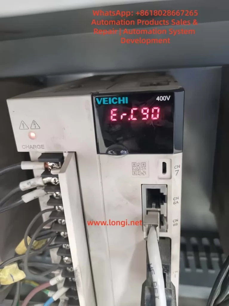
- The drive’s display shows the “AL-09” alarm code.
- The servo motor stops operating and cannot continue executing motion commands.
- The alarm indicator light turns on, usually red or yellow.
- The system may be accompanied by abnormal noises, such as motor humming or mechanical friction sounds.
- The upper-level machine or PLC may receive alarm signals, causing the entire control system to shut down.
3. Structure and Working Principle of LS Servo Drive APD-VP Series
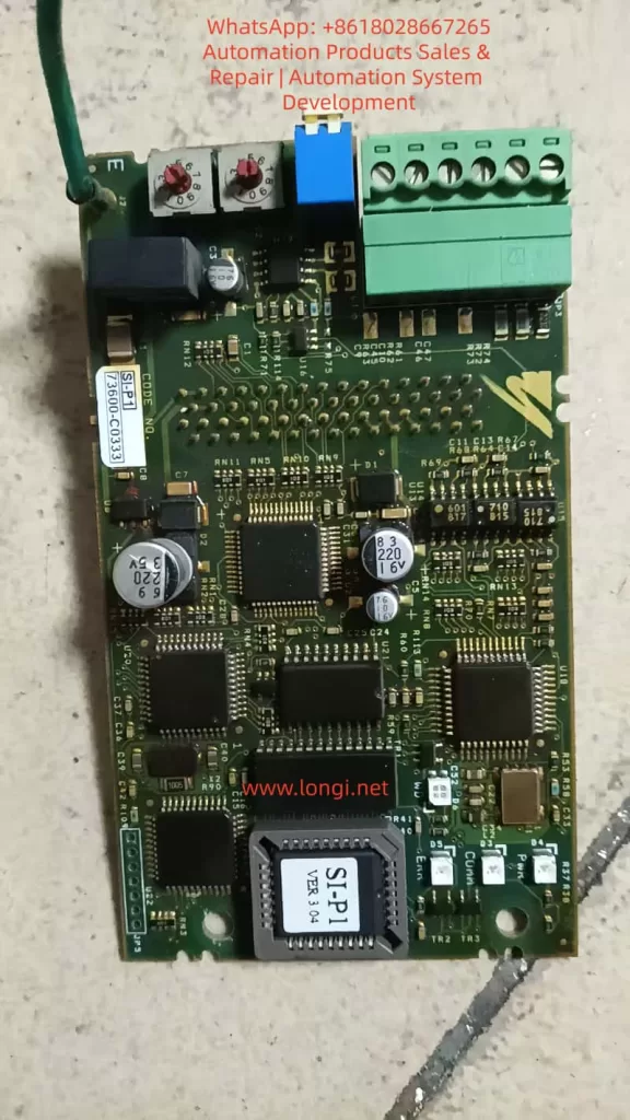
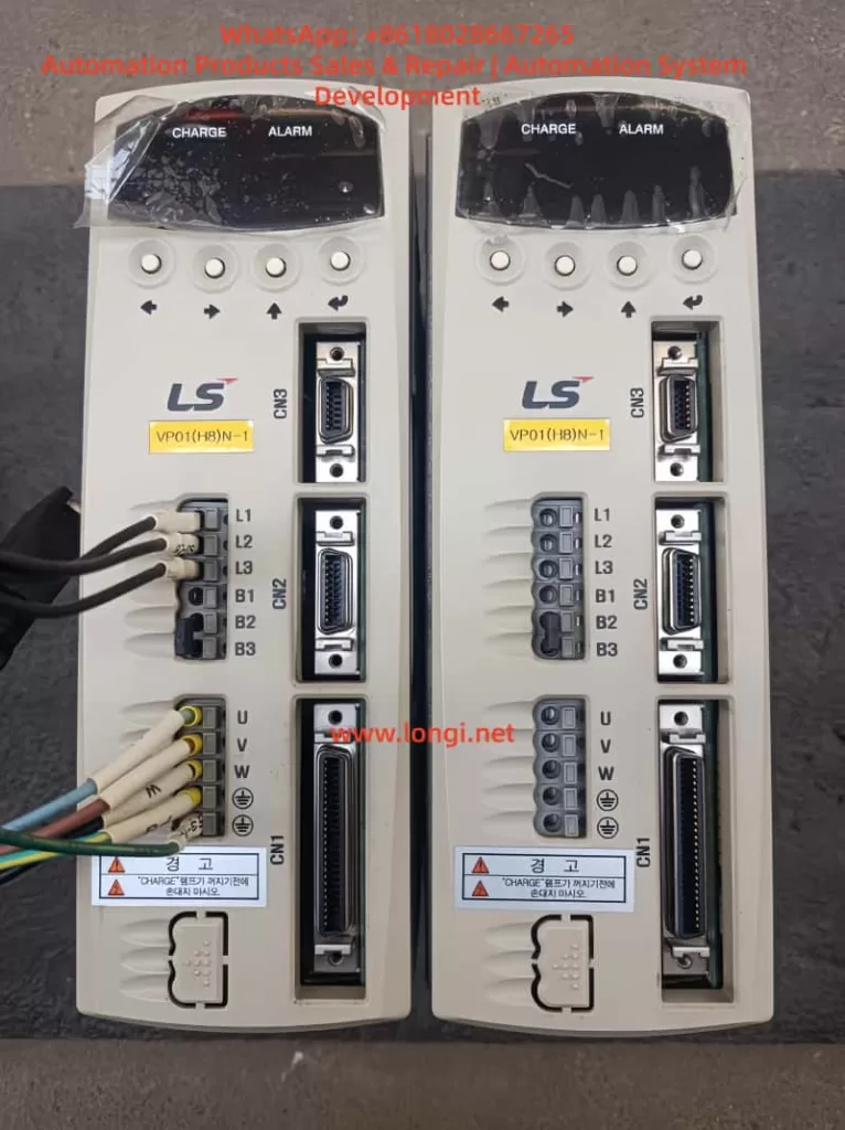
3.1 Hardware Structure of APD-VP Series Servo Drive
The LS servo drive APD-VP series adopts a modular design, primarily consisting of the following components:
- Main Circuit Board: Includes IGBT inverters, PWM control circuits, current/voltage detection circuits, etc., responsible for converting input AC power into controllable three-phase AC power to drive the servo motor.
- Control Circuit Board: Contains core control chips such as DSP (Digital Signal Processor) and FPGA (Field-Programmable Gate Array), responsible for motion control algorithms, parameter settings, communication interfaces, etc.
- Interface Board: Provides various input/output interfaces, including analog input/output, pulse input, encoder feedback interfaces, etc., for communication with upper-level machines, PLCs, sensors, and other devices.
- Power Supply Module: Supplies stable DC power to the internal circuits of the drive.
- Cooling System: Includes heat sinks and fans to ensure stable operation of the drive under high loads.
3.2 Control Logic and Feedback Mechanism of Servo Drive
The APD-VP series servo drive employs a closed-loop control method, achieving precise motion control through the following steps:
- Command Input: The upper-level machine (such as PLC or motion controller) sends motion commands (position, speed, or torque commands) to the drive.
- Control Algorithm: The internal DSP of the drive calculates the control output based on the commands and feedback signals (such as encoder pulses and current sensor signals).
- PWM Modulation: The control algorithm outputs PWM signals to drive the IGBT inverter, converting the DC bus voltage into variable frequency and amplitude three-phase AC power.
- Motor Drive: The three-phase AC power drives the servo motor.
- Feedback Detection: The encoder detects the motor’s position and speed in real-time, and the current sensor detects the actual current of the motor, sending feedback signals to the drive.
- Closed-Loop Adjustment: The drive compares the commands and feedback signals and adjusts the output through the PID controller to achieve precise control.
3.3 Working Principle of Overload Protection Mechanism
The APD-VP series servo drive is equipped with an overload protection mechanism, which operates as follows:
- Current Detection: The drive monitors the phase current of the motor in real-time. When the current exceeds the rated value, it triggers overload protection.
- Torque Calculation: The drive calculates the actual output torque based on the current and motor parameters (such as torque constant). When the torque exceeds the set torque limit ([PE-205], [PE-206]), it triggers overload protection.
- Load Monitoring: The drive calculates the actual load on the motor through encoder feedback and current detection. When the load exceeds the rated load (typically 300% of the rated torque), it triggers the AL-09 alarm.
- Protection Action: Once overload protection is triggered, the drive immediately cuts off the PWM output, stopping the motor and displaying the AL-09 alarm code.
4. Causes of AL-09 Fault
The causes of AL-09 overload faults are diverse and can be categorized as follows:
4.1 Mechanical Load Abnormalities
Mechanical load abnormalities are the most common cause of AL-09 faults, including:
- Mechanical Jamming: Transmission mechanisms (such as gears, guides, and screws) may jam or experience excessive friction, preventing the motor from rotating normally.
- Excessive Load: The actual load exceeds the motor’s rated load capacity, such as overweight workpieces or unreasonable mechanical design.
- Coupling Misalignment: The motor shaft and load shaft are misaligned, resulting in additional radial or axial forces that increase the motor load.
- Insufficient Lubrication: Transmission components lack lubrication, increasing friction and motor load.
4.2 Electrical Parameter Setting Errors
Incorrect parameter settings in the drive can directly affect the motor’s operating state. Common parameter setting errors include:
- Torque Limit Set Too Low: [PE-205] (CCW Torque Limit) and [PE-206] (CW Torque Limit) are set too low, causing the motor to trigger overload protection under normal loads.
- Incorrect Gain Parameter Settings: Speed proportional gain ([PE-307], [PE-308]) or position proportional gain ([PE-302], [PE-303]) are set too high, leading to system oscillation or overload.
- Electronic Gear Ratio Error: [PE-701] (Electronic Gear Ratio) is set incorrectly, causing a mismatch between pulse commands and actual positions, resulting in overload.
- Encoder Pulse Number Setting Error: [PE-204] (Encoder Pulse Number) does not match the actual encoder, leading to incorrect feedback signals and triggering overload protection.
4.3 Motor or Encoder Failures
Failures in the motor or encoder can also cause AL-09 alarms:
- Motor Winding Short Circuit or Open Circuit: Internal winding damage in the motor causes abnormal current increases.
- Encoder Signal Loss or Error: Encoder damage or loose wiring causes interruption or error in feedback signals.
- Motor Bearing Damage: Worn or jammed bearings increase the motor’s rotational resistance.
4.4 Power Supply Issues
The stability of the power supply directly affects the operation of the drive and motor:
- Voltage Fluctuations: Unstable input voltage, such as overvoltage or undervoltage, causes abnormal drive output.
- Poor Power Line Contact: Loose or oxidized power lines cause excessive voltage drops.
- Regenerative Resistor Failure: Damaged regenerative resistors or incorrect parameter settings prevent effective absorption of regenerative energy, leading to overvoltage or overload.
4.5 Environmental Factors
Environmental factors can indirectly cause AL-09 faults:
- High Temperature: Operation of the drive or motor in high-temperature environments leads to poor heat dissipation and performance degradation.
- Humidity or Corrosive Gases: Moisture or corrosive environments may cause short circuits or poor contact in the circuit board.
- Vibration or Impact: Mechanical vibration or impact may loosen or damage internal components of the drive.

5. Diagnostic Steps for AL-09 Fault
When the APD-VP series servo drive displays an AL-09 fault, follow these steps for diagnosis:
5.1 Preliminary Inspection
- Confirm Alarm Code: Verify that the alarm code displayed on the drive is AL-09.
- Check Mechanical Load: Manually rotate the motor shaft to confirm if there is jamming or abnormal resistance.
- Check Power Supply: Ensure the input voltage is within the allowed range (AC200-230V) and the power line is normal.
5.2 Mechanical System Inspection
- Inspect Transmission Mechanism:
- Ensure gears, guides, screws, and other transmission components are well-lubricated and free from jamming.
- Check if the coupling is aligned and free from offset or deformation.
- Check Load:
- Confirm that the load is within the motor’s rated range, such as workpiece weight and mechanical friction.
- Reduce the load and observe if the fault disappears.
5.3 Electrical Parameter Inspection
- Check Torque Limit:
- Enter menus [PE-205] and [PE-206] to confirm if the torque limit is set too low.
- If the torque limit is too low, increase the setting appropriately (usually not exceeding 300%).
- Check Gain Parameters:
- Check if the speed proportional gain ([PE-307], [PE-308]) and position proportional gain ([PE-302], [PE-303]) are too high.
- If the gain is too high, gradually reduce the gain value and observe if the fault disappears.
- Check Electronic Gear Ratio:
- Ensure [PE-701] (Electronic Gear Ratio) matches the mechanical transmission ratio.
- Check Encoder Settings:
- Ensure [PE-204] (Encoder Pulse Number) matches the motor nameplate.
5.4 Motor and Encoder Inspection
- Inspect Encoder:
- Ensure encoder wiring is secure and free from breaks or short circuits.
- Use an oscilloscope to check encoder signals (A, B, Z phases) for normality.
- Inspect Motor:
- Measure the insulation resistance of the motor windings to ensure no short circuits or open circuits.
- Manually rotate the motor shaft to ensure bearings are free from abnormal noises or jamming.
5.5 Power Supply and Wiring Inspection
- Check Power Supply:
- Use a multimeter to measure the input voltage, ensuring it is within the AC200-230V range.
- Check the power line for poor contact or oxidation.
- Check Regenerative Resistor:
- Ensure the regenerative resistor is connected correctly and parameters are set reasonably.
- Check if the regenerative resistor is damaged and if the resistance value is normal.
6. Solutions for AL-09 Fault
Based on the diagnostic results, the following solutions can be implemented:
6.1 Optimization and Adjustment of Mechanical Load
- Reduce Load:
- Lighten the workpiece weight or optimize the mechanical structure to reduce the motor load.
- Lubricate Transmission Components:
- Regularly add lubricating oil or grease to gears, guides, screws, and other transmission components.
- Adjust Coupling:
- Ensure the motor shaft and load shaft are aligned to avoid radial or axial forces.
6.2 Reconfiguration of Electrical Parameters
- Adjust Torque Limit:
- Based on the actual load, appropriately increase the torque limit values in [PE-205] and [PE-206].
- Optimize Gain Parameters:
- Gradually reduce the speed proportional gain ([PE-307], [PE-308]) and position proportional gain ([PE-302], [PE-303]) to avoid system oscillation.
- Recalibrate Electronic Gear Ratio:
- Reset [PE-701] (Electronic Gear Ratio) according to the mechanical transmission ratio.
6.3 Maintenance and Replacement of Motor and Encoder
- Replace Damaged Encoder:
- If the encoder signal is abnormal, replace it with a new one and ensure correct wiring.
- Repair or Replace Motor:
- If the motor windings or bearings are damaged, send them for repair or replace them with new ones.
6.4 Improvement of Power Supply Stability
- Stabilize Power Voltage:
- Use a voltage regulator or UPS (Uninterruptible Power Supply) to ensure stable input voltage.
- Check Power Line:
- Ensure the power line is in good contact and free from oxidation.
6.5 Control of Environmental Factors
- Improve Cooling Conditions:
- Ensure the cooling fans of the drive and motor operate normally to avoid high-temperature environments.
- Prevent Moisture and Corrosion:
- In humid or corrosive environments, take protective measures such as sealing the drive cabinet.
7. Preventive Measures for AL-09 Fault
To prevent the occurrence of AL-09 faults, the following measures can be taken:
7.1 Regular Maintenance and Upkeep
- Regularly Inspect Mechanical Transmission Components:
- Check the wear and lubrication of gears, guides, screws, and other components.
- Regularly Clean Drive and Motor:
- Remove dust and debris to ensure good heat dissipation.
- Regularly Check Electrical Connections:
- Ensure all terminal connections are secure and free from oxidation or loosening.
7.2 Parameter Backup and Optimization
- Backup Drive Parameters:
- Regularly back up the drive’s parameter settings for quick recovery after faults.
- Optimize Parameter Settings:
- Optimize parameters such as gain and torque limit based on actual load and operating conditions.
7.3 Runtime Monitoring and Alarm System
- Real-Time Monitoring of Operating Status:
- Use upper-level machines or PLCs to monitor motor current, speed, position, and other parameters in real-time.
- Set Alarm Thresholds:
- Set reasonable alarm thresholds in the drive to detect and handle abnormalities promptly.
8. Case Studies
8.1 Case Study 1: AL-09 Fault Caused by Mechanical Jamming
Fault Phenomenon: A CNC machine suddenly stopped during operation, and the drive displayed an AL-09 alarm. Manual rotation of the motor shaft revealed significant jamming in the screw transmission.
Diagnostic Process:
- Inspected the mechanical transmission and found that the screw guide lacked lubrication, causing excessive friction.
- Checked the drive parameters and found that the torque limit settings were normal.
Solution:
- Added lubricating oil to the screw guide.
- Adjusted the coupling alignment to reduce radial forces.
- Reset the alarm, and the equipment resumed normal operation.
Experience Summary: Mechanical jamming is a common cause of AL-09 faults. Regular maintenance and lubrication of transmission components are crucial.
8.2 Case Study 2: AL-09 Fault Caused by Parameter Setting Errors
Fault Phenomenon: An automated production line frequently displayed AL-09 alarms during debugging, and the motor failed to start normally.
Diagnostic Process:
- Inspected the mechanical load and found no abnormalities.
- Checked the drive parameters and found that the speed proportional gain ([PE-307]) was set too high, causing system oscillation.
Solution:
- Gradually reduced the speed proportional gain until the system stabilized.
- Optimized other control parameters, such as the integral time constant ([PE-309]).
- Reset the alarm, and the equipment operated normally.
Experience Summary: Parameter setting errors are another significant cause of AL-09 faults. During debugging, parameters should be adjusted gradually to avoid excessive settings.
8.3 Case Study 3: AL-09 Fault Caused by Unstable Power Supply
Fault Phenomenon: A packaging machine suddenly stopped during operation, and the drive displayed an AL-09 alarm. Inspection revealed significant voltage fluctuations in the input power.
Diagnostic Process:
- Used a multimeter to measure the input voltage, which fluctuated between 180V and 250V.
- Inspected the power line and found poor contact causing excessive voltage drops.
Solution:
- Replaced the power line to ensure good contact.
- Added a voltage regulator to stabilize the input voltage.
- Reset the alarm, and the equipment resumed normal operation.
Experience Summary: Unstable power supply can cause abnormal drive output, triggering overload protection. Ensuring power stability is key to preventing AL-09 faults.
9. Conclusion and Recommendations
AL-09 overload faults are common issues in the LS servo drive APD-VP series in practical applications. Through this analysis, we can draw the following conclusions:
- AL-09 faults have diverse causes, including mechanical load abnormalities, electrical parameter setting errors, motor or encoder failures, power supply issues, and environmental factors.
- Diagnosing AL-09 faults requires a systematic approach, involving inspections from mechanical, electrical, and environmental perspectives.
- Solving AL-09 faults requires targeted measures, such as optimizing mechanical loads, adjusting electrical parameters, maintaining motors and encoders, and stabilizing power supplies.
- Preventing AL-09 faults requires proactive measures, including regular maintenance, parameter optimization, and runtime monitoring.
Recommendations:
- Establish Equipment Maintenance Records: Document the equipment’s operating status, fault history, and maintenance activities.
- Regularly Train Operators: Enhance their ability to diagnose and handle servo drive faults.
- Introduce Remote Monitoring Systems: Monitor equipment operating status in real-time to detect and address abnormalities promptly.