Posted on Leave a comment

Fuji Inverter FRENIC 5000 G11S/P11S Series User Manual Guide

I. Operation Panel Function Introduction

The operation panel of the Fuji INVERTER FRENIC 5000 G11S/P11S series is the primary interface for user interaction with the frequency converter. It is equipped with a series of buttons and an LED display for setting parameters, monitoring operating status, and executing control operations.

Fuji FRENIC5000G11SP11S KEYPAD PANEL

1.1 Button Functions

  • FWD/REV Keys: Used to start the frequency converter, enabling the motor to rotate forwards or backwards.
  • STOP Key: Used to stop the frequency converter.
  • ∨ or ∨ Keys: In program mode, these keys are used to vertically move the cursor to select function codes or data.
  • FUNC DATA Key: In program mode, this key is used to store modified data or switch display screens.
  • RESET Key: In program mode, this key is used to cancel the current input data; in fault mode, it is used to release the fault stop status.
  • PRG Key: Used to switch between operation mode and program mode.
  • SHIFT Key (Column Shift): In program mode, when used in combination with the ∨ or ∨ keys, it moves the cursor horizontally.

1.2 Restoring Factory Default Parameter Settings

To restore factory default parameter settings, follow these steps:

  1. Press the PRG key to enter program mode.
  2. Use the ∨ or ∨ keys to select “1. DATA SET”.
  3. Press the FUNC DATA key to confirm the selection.
  4. Simultaneously press the STOP key and the ∨ key to change the parameter protection value from “1” to “0”, allowing parameter modifications.
  5. Again, use the ∨ or ∨ keys to select “F00 Data protection” and set its value to “0”.
  6. Press the FUNC DATA key to save the settings. The frequency converter will restart and restore the factory default parameters.

1.3 Setting and Clearing Passwords

The Fuji FRENIC G11S/P11S series provides password protection to restrict access to parameters. However, the specific methods for setting and clearing passwords are not detailed in the provided manual. Typically, such functions may require setting through specific parameter codes, and the unlocking process may involve the manufacturer or authorized service personnel. It is recommended to refer to Fuji’s official technical support documentation or contact the manufacturer for detailed guidance.

Fuji FRENIC5000 G11S/G9S Inverter wiring-diagraml

II. Terminal Start/Stop and Potentiometer Speed Regulation

2.1 Terminal Start/Stop

The Fuji FRENIC G11S/P11S series supports start/stop control via external terminals. To achieve this, relevant parameters need to be set correctly, and wiring must be done accordingly:

  • Parameter Setting: Set function code F02 to “1” to select external signal input mode.
  • Wiring: Connect the control power to terminals R0 and T0; connect the start signal (e.g., FWD) to the corresponding digital input terminal (e.g., X1); connect the stop signal to the REST terminal.

2.2 Potentiometer Speed Regulation

Potentiometer speed regulation is a method of changing the frequency output by adjusting the resistance value of an external potentiometer. The setup steps are as follows:

  • Parameter Setting: Set function code F01 to “1” to select voltage input mode.
  • Wiring: Connect the output terminal of the potentiometer to the frequency setting terminal of the frequency converter (e.g., terminal 12), and simultaneously ground the common terminal of the potentiometer (e.g., 0V terminal).

III. Frequency Converter Fault Code Analysis and Solutions

When the Fuji FRENIC G11S/P11S series encounters a fault, it will display the corresponding error code, helping users quickly locate the problem. The following are some common fault codes, their analyses, and solutions:

  • OC1: Overcurrent during acceleration. Possible causes include motor blockage, excessive load, or improper parameter settings. Solutions include checking the motor and load status, and adjusting acceleration time and current limit parameters.
  • OU: DC bus overvoltage. Possible causes include braking resistor failure, excessively short deceleration time, or abnormal supply voltage. Solutions include checking the braking resistor and wiring, and adjusting deceleration time and voltage limit parameters.
  • OL: Electronic thermal relay overload. Possible causes include motor overload, poor heat dissipation, or improper parameter settings. Solutions include checking the motor load and heat dissipation conditions, and adjusting the overload protection parameters.
  • Er1: Memory error. Possible causes include internal frequency converter faults or program abnormalities. Solutions include restarting the frequency converter; if the problem persists, contact the manufacturer for repair.

Summary

The Fuji Inverter FRENIC 5000 G11S/P11S series user manual provides detailed operation guides and parameter setting instructions, helping users fully utilize the various functions of the frequency converter. Through this guide, users can understand the functions of the operation panel, the method for restoring factory default parameter settings, the setup steps for terminal start/stop and potentiometer speed regulation, as well as the analysis and solutions for common fault codes. This information is crucial for ensuring the normal operation and efficient use of the frequency converter.

Posted on Leave a comment

Operation Guide for Yaskawa Inverter H1000 Series User Manual

I. Operation Panel Function Introduction and Usage Instructions

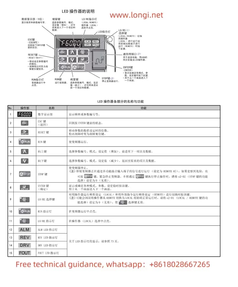
The operation panel of the Yaskawa Inverter H1000 series serves as its control hub, enabling parameter setting, monitoring of operating status, and fault diagnosis. The primary buttons and functions on the operation panel include:

Function diagram of Yaskawa INVERTER H1000 operation panel
  • ESC: Exits the current mode or cancels operations.
  • RUN: Starts the inverter.
  • STOP: Stops the inverter.
  • ENTER: Confirms inputs or enters parameter settings.
  • RESET: Resets faults.
  • ALM: Displays fault or warning messages.
  • DIGIT: Selects digits during parameter setting.
  • OPRATOR: The operation panel display, which shows various information and parameters.

Parameter Initialization

Parameter initialization restores the inverter’s settings to the factory defaults. The steps are as follows:

  1. Enter Initialization Mode: Press the “ESC” button on the operation panel, then press “ENTER” to enter the parameter setting mode.
  2. Select Initialization Parameter: Use the “DIGIT” buttons to select parameter “A1-03” and press “ENTER”.
  3. Set Initialization Value: Set the value of “A1-03” to “2220” or “3330” for initialization of 2-wire or 3-wire sequential control, respectively.
  4. Confirm and Save: Press “ENTER” to confirm the setting, and the inverter will automatically restart and complete the initialization.

Setting and Resetting Passwords

To protect the inverter settings from unauthorized changes, passwords can be set. The steps are as follows:

  1. Enter Password Setting Mode: In the parameter setting mode, select “A1-04” and press “ENTER”.
  2. Enter Password: Use the “DIGIT” buttons to input a 4-digit password and press “ENTER” to confirm.
  3. Confirm Password: Enter the same password again to confirm the setting and press “ENTER”.

To reset the password, simply enter the correct password in the password input interface to unlock the parameter settings.

Wiring diagram of Yaskawa INVERTER H1000 series control circuit

II. Terminal Start/Stop and External Potentiometer Speed Adjustment

To achieve terminal start/stop and external potentiometer speed adjustment, the corresponding control terminals need to be connected and parameters set accordingly.

Wiring Instructions

  1. Start/Stop Terminals: Typically, use terminals S1 (Run) and S2 (Stop). Closing (connecting) terminal S1 starts the inverter, while closing terminal S2 stops it.
  2. External Potentiometer: Use terminal A1 as the input terminal for the external potentiometer. Connect the potentiometer’s output to terminal A1 and adjust the potentiometer to change the frequency command.

Parameter Settings

  1. Run Command Selection: Set parameter “b1-01” to “10” to select the operation panel as the frequency command source.
  2. Multi-function Input Settings: Set parameter “H1-01” to “04” (Run command) and “H1-02” to “05” (Stop command), corresponding to the functions of terminals S1 and S2, respectively.
  3. Analog Input Gain and Offset: Adjust parameters “H3-03” (Gain) and “H3-04” (Offset) according to the output range of the external potentiometer to ensure that the frequency command changes proportionally with the potentiometer output.

III. Crane Control Wiring and Parameter Setup

In crane applications, special attention must be paid to safety control and precise speed regulation.

Wiring Instructions

  1. Main Circuit Wiring: Connect the inverter’s R/L1, S/L2, and T/L3 terminals to the crane motor according to its voltage and power requirements.
  2. Control Circuit Wiring: In addition to the basic start/stop terminals, emergency stop, limit switches, and other safety control terminals also need to be connected.
  3. PG (Encoder) Wiring: For cranes requiring precise speed control and positioning, connect the PG encoder and output its signals to the inverter’s PG option card.

Parameter Settings

  1. Control Mode Selection: Set parameter “A1-02” to the appropriate vector control mode (e.g., Vector Control with PG) to ensure precise speed and position control.
  2. PG Parameter Settings: Set parameters such as “F1-06” (PG Output Division Ratio) and “F1-12/F1-13” (PG Gear Ratio) according to the encoder specifications.
  3. Safety Function Settings: Enable the external emergency stop function and set the relevant parameter, such as “H2-01” (Multi-function Contact Output Selection), to output an emergency stop signal.
  4. Speed Search Function: For heavy-duty applications like cranes, it is recommended to enable the speed search function to improve stability and safety during startup. Set parameter “b3-01” to effective and adjust other related parameters as needed.

IV. Fault Code Meanings and Solutions

The Yaskawa Inverter H1000 series has comprehensive fault self-diagnosis functions. When a fault occurs, the operation panel will display the corresponding fault code. Below are the meanings of some common fault codes and their solutions:

  • CPF00/CPF01: Control circuit fault. Possible causes include incorrect control circuit wiring or damaged circuit boards. The solution is to check the control circuit wiring and replace the circuit board if necessary.
  • oH: Overheating of the heatsink. Possible causes are high ambient temperature, excessive load, or a faulty cooling fan. The solution is to improve ventilation, reduce the load, or replace the cooling fan.
  • Uv: Undervoltage in the main circuit. Possible causes are low supply voltage or phase loss in the power supply. The solution is to check the supply voltage and wiring to ensure they are normal.
  • oL1: Motor overload. Possible causes are excessive load or improper motor parameter settings. The solution is to reduce the load or reset the motor parameters.

When a fault occurs in the inverter, first check the fault code displayed on the operation panel to identify the cause and follow the corresponding solution. If the issue cannot be resolved, promptly contact a professional technician for repairs.

Through this operation guide, users can better understand and operate the Yaskawa Inverter H1000 series, ensuring its stable operation in various applications.

Posted on Leave a comment

User Manual Guide for INVT INVERTER Goodrive 10 (GD10) Series

I. Function Introduction of VFD Operation Panel (Keyboard)

The operation panel (keyboard) of the INVT Goodrive 10 series INVERTER serves as the primary interface for user interaction. This keyboard is highly functional, capable of performing basic operations, status monitoring, and parameter settings on the INVERTER. Here are some key functions:

Function diagram of the operation panel of the NVIDIA GD10 Inverter
  1. Status Indicators:
    • RUN/TUNE: Indicates whether the INVERTER is running.
    • FWD/REV: Indicates the forward or reverse rotation status of the motor.
    • LOCAL/REMOT: Indicates the current control mode (local keyboard control or remote communication control).
    • TRIP: Indicates whether the INVERTER is in a fault state.
  2. Digital Display Area: A 5-digit LED display for showing set frequencies, output frequencies, currents, voltages, and various monitoring data and alarm codes.
  3. Operation Buttons:
    • PRG/ESC: Programming key for entering or exiting the parameter setting menu.
    • DATA/ENT: Confirmation key for validating parameter settings or entering the next menu level.
    • UP/DOWN: Increment/decrement keys for adjusting parameter values.
    • SHIFT: Right shift key for selecting different modification bits during parameter setting.
    • RUN/STOP/RST: Run/Stop/Reset keys for controlling the start, stop, and fault reset of the INVERTER.
    • QUICK/JOG: Quick multifunction key, whose function is set by parameter P07.02 and can include jogging, display state switching, etc.
Control Circuit and Terminal Wiring Diagram of AD10 Inverter from Envision

II. Methods for Setting and Deleting Passwords on the INVERTER

  1. Setting a Password:
    • Enter the parameter setting menu (press PRG/ESC). Locate parameter P07.00 and set it to a non-zero value, which will serve as the user password. After exiting the parameter setting menu, password protection will be activated.
  2. Deleting a Password:
    • Set parameter P07.00 to 0 to disable password protection. Note that password deletion must be performed without password protection in place.

III. Steps to Restore the INVERTER to Factory Defaults

To restore the INVERTER to its factory settings, follow these steps:

  1. Enter the parameter setting menu (press PRG/ESC).
  2. Locate parameter P00.18 and set it to 1 (restore default values). The INVERTER will begin restoring default parameters, which may take a few seconds.
  3. After restoration, parameter P00.18 automatically reverts to 0. At this point, the INVERTER has been restored to its factory settings.

IV. Specific Steps for Terminal Start/Stop and External Potentiometer Speed Adjustment

Wiring Steps:

  1. Start/Stop Terminal Wiring:
    • Connect the start signal from the external control circuit to the S1 terminal of the INVERTER and the stop signal to the S2 terminal.
    • Ensure that the control circuit power matches the INVERTER’s control power.
  2. External Potentiometer Wiring:
    • Connect the output end of the potentiometer to the AI1 terminal (analog input terminal) of the INVERTER.
    • Connect the power end of the potentiometer to an appropriate power source, typically a 10V DC power supply.

Parameter Setting Steps:

  1. Set the Run Command Channel:
    • Enter the parameter setting menu and locate parameter P00.01. Set it to 1 (terminal run command channel).
  2. Set the Analog Input Function:
    • Locate parameter P00.06 and set it to 1 (keyboard analog AI1 setting). This way, the frequency of the INVERTER will be determined by the analog input from the AI1 terminal.
  3. Adjust Other Related Parameters (if necessary):
    • Adjust acceleration time, deceleration time, maximum output frequency, and other parameters based on actual application requirements to achieve optimal control performance.

V. Analysis and Solution of INVERTER Fault Codes

The Goodrive 10 series INVERTER features comprehensive fault protection functions, capable of monitoring the INVERTER’s operating status in real-time and providing fault codes when issues arise. Here are some common fault codes and their solutions:

  1. OV1 (Acceleration Overvoltage):
    • Possible Causes: Excessively high input voltage; too short deceleration time.
    • Solutions: Check if the input voltage is normal; increase the deceleration time as needed.
  2. OC1 (Acceleration Overcurrent):
    • Possible Causes: Excessive load; low grid voltage.
    • Solutions: Check if the load exceeds the INVERTER’s rated load; check if the grid voltage is normal.
  3. UV (Bus Undervoltage Fault):
    • Possible Causes: Low grid voltage; input power phase loss.
    • Solutions: Check if the grid voltage is normal; check for input power phase loss.
  4. OH2 (Inverter Module Overheat Fault):
    • Possible Causes: High ambient temperature; poor heat dissipation.
    • Solutions: Improve the INVERTER’s heat dissipation conditions; reduce the ambient temperature.

When the INVERTER encounters a fault, users should first refer to the fault code to identify possible causes and apply the corresponding solutions. If the problem persists, contact INVT’s technical support for assistance.

VI. Conclusion

The user manual for the INVT Goodrive 10 series INVERTER serves as an essential reference for users to operate and maintain the INVERTER. This document provides detailed information on the INVERTER’s operation panel functions, password setting and deletion, steps to restore factory defaults, specific procedures for terminal start/stop and external potentiometer speed adjustment, as well as fault code analysis and solutions. We hope this content will help users better utilize and maintain the Goodrive 10 series INVERTER.

Posted on Leave a comment

What Does “LL” Fault Mean on Eura Drives E800 Series Inverter, and How to Solve It?

Introduction

The E800 series of Eura Drives inverters is a widely used device in the field of industrial control, with its stability and reliability being crucial to users’ production activities. However, in practical applications, users may encounter various faults and issues, among which the “LL” fault displayed upon power-up is a particularly perplexing one.

The label of Eura Drives E800 Inverter

The Meaning of “LL” Fault

Upon power-up, if the E800 series inverter of Eura Drives displays the “LL” fault code and cannot be reset by pressing any buttons, it typically indicates a specific issue with the inverter. Unfortunately, the user manual may not explicitly state the meaning of the “LL” fault code. However, within the communication section, under the explanation of communication address meanings, the operational status parameter address 1005 mentions the inverter status: “OXOC (LL)”.

Despite the brief mention, there is no further elaboration on the “LL” fault code in the manual. Nevertheless, based on our experience and understanding of inverter fault codes, the “LL” fault on Eura Drives E800 series inverters generally indicates a low voltage fault. This means that the input voltage to the inverter is below the acceptable range, causing the inverter to malfunction and display the “LL” fault code.

Physical image of Eura Drives inverter displaying LL fault

Solutions to the “LL” Fault

To resolve the “LL” fault on Eura Drives E800 series inverters, the following steps can be taken:

  1. Check the Input Voltage:
    • Verify that the input voltage supplied to the inverter is within the specified range. For the E800 series, the input voltage range is typically three-phase 380V to 480V (with a tolerance of +10% to -15%) or single-phase 220V to 240V (with a tolerance of ±15%).
    • Use a voltmeter to measure the voltage at the inverter’s input terminals.
  2. Inspect the Power Supply:
    • Ensure that the power supply is stable and reliable. Check for any potential issues such as voltage fluctuations, surges, or drops that may affect the input voltage to the inverter.
  3. Review the Wiring:
    • Examine the wiring between the power source and the inverter to ensure that it is correct and free from any damage or loose connections.
  4. Check the Fuse and Circuit Breaker:
    • Verify that the fuse or circuit breaker protecting the inverter’s power supply circuit is not blown or tripped. Replace it if necessary.
  5. Consult the Manual and Technical Support:
    • If the issue persists after checking the above points, refer to the user manual for additional troubleshooting steps or contact Eura Drives’ technical support for assistance.
  6. Reset the Inverter:
    • Once the issue with the input voltage has been resolved, try resetting the inverter by pressing the reset button or cycling the power to see if the “LL” fault code clears.

Conclusion

The “LL” fault on Eura Drives E800 series inverters is generally indicative of a low voltage issue. By carefully checking the input voltage, power supply, wiring, fuse, and circuit breaker, and taking appropriate corrective actions, users can often resolve this fault and restore normal operation of the inverter. If the problem persists, seeking assistance from the manufacturer’s technical support is recommended.

Posted on Leave a comment

User Manual for Invt GD300-01A-RT Series VFD Dedicated for Air Compressors – Usage Guide

This guide aims to assist users in better understanding and utilizing the Invt GD300-01A-RT Series VFD, a single frequency converter specifically designed for air compressor control, featuring efficiency, ease of use, and reliability. Below is a detailed usage guide.

GD300-01A-RT menu interface diagram

I. Operating Methods for Controlling Air Compressors

  1. Wiring Method
    Main Circuit Wiring:
    Connect the power input terminals (R, S, T or L1, L2, L3) to the electrical grid.
    Connect the motor output terminals (U, V, W) to the main motor of the air compressor.
    The grounding terminal PE must be grounded with a grounding resistance of less than 10Ω.
    Control Circuit Wiring:
    Connect signal lines, such as pressure sensors and temperature sensors, to the corresponding input terminals (e.g., P1+, P1-) as per actual requirements.
    Connect external control signals (e.g., start, stop, load, unload) to the respective input terminals (e.g., S1, S2, S3).
    If needed, connect fault outputs, alarm outputs, etc., to external devices.
  2. Parameter Settings
    Motor Parameter Settings:
    Enter the “Main Unit Parameter Settings” interface and set parameters such as motor type, rated power, rated frequency, rated voltage, and rated current based on the actual motor nameplate parameters.
    Perform motor parameter self-learning to ensure the VFD can accurately control the motor.
    Air Compressor-Specific Parameter Settings:
    Set the range and calibration points for pressure sensors and temperature sensors.
    Set parameters such as loading pressure, unloading pressure, no-load operating frequency, and minimum loading operating frequency to suit the operational needs of the air compressor.
    Set parameters such as fan control mode and maintenance timeout as required.

II. Using External Terminals for Starting and External Potentiometer for Frequency Adjustment

  1. Wiring Method
    External Start Terminal Wiring:
    Connect the external start signal (e.g., push-button switch) to the S1 terminal (forward start) and the COM terminal.
    For reverse start, connect the signal to the S2 terminal.
    External Potentiometer Wiring:
    Connect the center tap of the external potentiometer to the AI1 terminal (analog input 1).
    Connect the other two terminals of the potentiometer to +10V and GND terminals to provide the required power supply voltage for the potentiometer.
  2. Parameter Settings
    Operation Command Channel Settings:
    Enter the “Basic Function Group” parameter settings and set P00.01 to 1 (terminal operation command channel).
    Frequency Command Selection:
    Set P00.06 to 1 (analog P1-setting) to enable external potentiometer frequency adjustment.
GD300-01A-RT system wiring diagram

III. Setting Password Function and Restoring Factory Settings

  1. Setting Password Function
    Enter the “Human-Machine Interface Group” parameter settings and locate the P07.00 (user password) parameter.
    Enter the desired password value (0~65535) and save the settings.
    After setting the password, the correct password must be entered for parameter modification.
  2. Restoring Factory Settings
    Enter the “Basic Function Group” parameter settings and locate the P00.18 parameter.
    Set P00.18 to 1 (restore default values) and save the settings.
    The VFD will automatically restore to the factory default parameter settings.

IV. Fault Analysis and Handling Methods

  1. Fault Code Query
    When a fault occurs in the VFD, first check the fault code on the VFD panel.
    Refer to the “VFD Faults and Countermeasures” section in the manual based on the fault code to find possible fault causes and corrective actions.
  2. Fault Troubleshooting Steps
    Check the power supply and wiring: Ensure normal power input and secure wiring.
    Check external control signals: Ensure normal input of external control signals (e.g., start, stop, load, unload).
    Check sensor signals: Ensure normal input of signals from pressure sensors, temperature sensors, etc., and correct range and calibration point settings.
    Check the motor and load: Ensure normal motor operation and no abnormalities in the load.
  3. Fault Handling Examples
    Overcurrent Fault (OC1, OC2, OC3):
    Check if the grid voltage is too low.
    Check for short circuits or locked rotor phenomena in the motor and load.
    Increase the acceleration/deceleration time or select a VFD with a higher power.
    Overvoltage Fault (OV1, OV2, OV3):
    Check if the input power voltage is too high.
    Check for energy feedback phenomena and add energy consumption braking components if necessary.
    Undervoltage Fault (UV):
    Check if the grid voltage is too low or fluctuating significantly.

By following this usage guide, users can better grasp the operation of the Invt GD300-01A-RT Series VFD dedicated for air compressors, ensuring stable operation of the air compressor system.

Posted on Leave a comment

ABB VFD ACS510 Series F0035 Fault (Fault 35) Cause Analysis and Troubleshooting Methods

Introduction

The ABB VFD (Variable Frequency Drive) ACS510 series is widely utilized in industrial applications due to its high efficiency, reliability, and ease of maintenance. However, users may encounter various fault alarms during operation, with F0035 (Fault 35) being a relatively common one. This article will combine the content of the ABB VFD ACS510 series user manual with relevant online information to provide a detailed analysis of the causes of F0035 faults and corresponding troubleshooting methods.

ACS510 vfd FAULT 35

Overview of F0035 Fault

The F0035 fault, also known as “OUTPUT WIRING” fault, refers to an alarm triggered by the VFD when it detects incorrect connections between the input power cables and output power cables. According to the ABB VFD ACS510 series user manual, when the drive is stopped, this fault code monitors the correct connection of the input and output power cables. If a connection error is detected, the VFD will alarm and stop working to prevent possible equipment damage or safety accidents.

Cause Analysis of F0035 Fault

1. Incorrect Input Cable Connection

Incorrect input cable connection is one of the main causes of F0035 faults. If the supply voltage is mistakenly connected to the drive output terminal, the VFD will be unable to function correctly and will trigger an F0035 fault alarm. This connection error may result from negligence or misoperation by the wiring personnel.

2. Incorrect Output Cable Connection

In addition to incorrect input cable connections, incorrect output cable connections can also lead to F0035 faults. If the output power cables of the drive are connected improperly, such as reversed phase sequence or phase loss, the VFD will be unable to control the motor correctly, thereby triggering a fault alarm.

3. Capacitance Effect of Input Power Cables

In some cases, even if the input power cables are connected correctly, a large capacitance of the cables may cause false F0035 fault alarms. Especially when the input power cables are connected in a delta configuration, the capacitance effect may be more pronounced. This is because capacitance generates current in AC circuits, interfering with the normal operation of the VFD.

4. Environmental Interference

Environmental factors, such as electromagnetic interference, excessive temperature, and high humidity, may also affect the normal operation of the VFD, triggering F0035 faults. Particularly in industrial settings, electromagnetic interference is a non-negligible issue.

Troubleshooting Methods for F0035 Fault

1. Check and Correct Cable Connections

First, it is necessary to carefully inspect the connections of the input power cables and output power cables. Ensure that the supply voltage is correctly connected to the input terminal of the VFD, and the output power cables are correctly connected to the motor terminal, with phase sequence, phase, and other parameters meeting requirements. If any connection errors are found, they should be corrected immediately.

2. Disable Wiring Fault Detection Using Parameter 3023

If the capacitance of the input power cables is large and frequently triggers false F0035 fault alarms, consider disabling the wiring fault detection function using parameter 3023 WIRING FAULT. In the stopped state of the VFD, set the value of parameter 3023 to 1 to disable wiring fault detection. However, it should be noted that disabling this function may reduce the fault protection capability of the VFD, so it should be used cautiously.

3. Enhance Electromagnetic Interference Protection

For F0035 faults caused by electromagnetic interference, the following measures can be taken for protection:

  • Use shielded cables or twisted pairs with better anti-interference performance;
  • Install filters or isolation transformers at the input and output terminals of the VFD;
  • Install the VFD away from sources of electromagnetic interference, such as high-power motors and high-frequency welding equipment.

4. Improve Operating Environment

To address F0035 faults caused by environmental factors, the following measures can be taken to improve the operating environment:

  • Maintain cleanliness and dryness in the VFD operating environment to avoid the impact of dust and moisture on the VFD;
  • Enhance ventilation and heat dissipation to ensure that the VFD operating temperature remains within the normal range;
  • For VFDs installed outdoors or in harsh environments, add protective covers or take other protective measures.

5. Regular Maintenance and Inspection

Regular maintenance and inspection of the VFD are effective measures to prevent F0035 faults. Maintenance personnel should regularly check cable connections, measure input and output voltages and currents to ensure their normalcy, and clean dust inside the VFD. Additionally, they should pay attention to the operating status and alarm records of the VFD to promptly identify and address potential issues.

Conclusion

The F0035 fault is a common fault alarm in the ABB VFD ACS510 series, with causes including incorrect input cable connections, incorrect output cable connections, capacitance effects of input power cables, and environmental interference. To address these causes, corresponding troubleshooting methods can be adopted, such as checking and correcting cable connections, disabling wiring fault detection using parameter 3023, enhancing electromagnetic interference protection, improving the operating environment, and regular maintenance and inspection. By implementing these measures, the incidence of F0035 faults can be effectively reduced, improving the operational reliability and stability of the VFD.

Posted on Leave a comment

Operation Guide for Mitsubishi VFD FR-D700 (D740,D720)Series User Manual

I. Introduction to VFD Operation Panel Functions
The operation panel of the Mitsubishi VFD FR-D700 series(D740,D720) is straightforward, facilitating various settings and operations for users. The panel primarily includes the following buttons and a rotary potentiometer:

Mitsubishi VFD FR-D700 Operation Panel Function Diagram

RUN: Press this button to start the VFD.
STOP/RESET: Press this button to stop the VFD or reset alarms.
MODE: Mode switching button used to toggle between different setting and display modes.
SET: Confirmation button used to confirm current settings or enter the next menu level.
PU/EXT: Operation mode switching button used to switch between PU (operation panel) mode and EXT (external terminal) mode.
Rotary Potentiometer: Used to manually adjust the output frequency of the VFD.

Setting Operation Modes
The VFD offers multiple operation modes, which can be set via parameter P79:

P79=0: PU operation mode, controlled via buttons and the rotary potentiometer on the operation panel.
P79=2: External operation mode, receiving start, stop, and speed commands via external terminals.

II. Terminal Start/Stop and External Potentiometer Speed Adjustment
Wiring Instructions
To achieve terminal start/stop and external potentiometer speed adjustment, proper wiring to the corresponding terminals of the VFD is required. Typically, the wiring is as follows:

STF (Forward Start): Connect to the normally open contact of an external start button or relay.
STR (Reverse Start): If reverse function is needed, connect to the normally open contact of an external reverse start button or relay.
SD (Stop): Connect to the normally closed contact of an external stop button or relay.
RH, RM, RL (Speed Setting): These terminals are typically used to connect an external potentiometer for speed adjustment. Among them, RH and RL are connected to the two ends of the potentiometer, and RM is connected to the sliding contact of the potentiometer.

Parameter Settings
Apart from proper wiring, relevant parameters need to be set to ensure the VFD operates as expected:

P79: Set to 2 to select external operation mode.
Pr7, Pr8: Set acceleration and deceleration times respectively to suit different application needs.
Pr9: Set the electronic overcurrent protection parameter to protect the VFD and motor from overcurrent damage.

Mitsubishi VFD FR-D700 Series External Wiring Diagram

III. VFD Fault Code Analysis and Solutions
When faults occur in the Mitsubishi VFD FR-D700 series, corresponding error codes are displayed, allowing users to analyze and resolve the faults. Below are some common fault codes and their solutions:

ER1: Overcurrent during acceleration. Check if the motor is overloaded, if there is a short circuit in the output, and if the acceleration time is set too short.
ER2: Overcurrent during constant speed. Check for sudden changes in load, and if there is a short circuit in the output.
ER3: Overcurrent during deceleration. Check for rapid deceleration, if there is a short circuit in the output, and if the motor’s mechanical brake is applied too early.
OL: Overspeed prevention (overcurrent). Check if the motor is overloaded.
TH: Motor overheat. Check if the motor is operating overloaded for a long time, if the ambient temperature is too high, and if the cooling system is functioning properly.
PS: PU stop. Check if the STOP button on the operation panel is pressed.
MT: Main circuit terminal abnormality. Check if the connections of the main circuit terminals are loose or damaged.
uV: Undervoltage protection. Check if the power supply voltage is too low, and if there is a large-capacity motor starting up causing instantaneous voltage drop.

Solutions
For overcurrent faults (ER1, ER2, ER3, OL): First, check if the motor and load are normal, then adjust acceleration time, deceleration time, and electronic overcurrent protection parameters.
For overheating faults (TH): Improve the motor’s cooling conditions, such as adding fans or lowering the ambient temperature.
For PU stop (PS): Confirm if the STOP button was pressed by mistake; if not, check the related control circuits.
For main circuit terminal abnormality (MT): Check and tighten the connections of the main circuit terminals, and replace if damaged.
For undervoltage protection (uV): Check if the power supply voltage is stable, and consider adding a power supply voltage stabilizing device.

The above is the operation guide for the Mitsubishi VFD FR-D700 series user manual, hoping to assist users in practical operations. If encountering other issues during use, it is recommended to refer to the detailed user manual of the VFD or contact professional technicians of longi for consultation.

Posted on Leave a comment

User Guide for Danfoss VLT2800 Frequency Converter


Danfoss VLT2800 Frequency Converter User Guide

1. Introduction to the Operation Panel

The operation panel of the Danfoss VLT2800 frequency converter is designed to be simple and user-friendly, allowing users to control basic functions and adjust parameters. The key components of the panel are:

  1. Display Screen: Shows current status, parameter values, fault codes, etc.
  2. Navigation Keys: Used to navigate between menus and parameters, including arrow keys for up, down, left, and right.
  3. Operation Keys: Includes keys for start, stop, reset, and other control functions for easy operation.
  4. Quick Menu Key: Provides quick access to commonly used menus and parameters.
  5. Change Data Keys: These keys allow users to modify displayed parameters and adjust the operating status of the converter.

With these buttons, users can perform parameter settings, switch operating modes, and monitor the running status of the frequency converter in real-time.

VLT2800 Multi Panel Function Diagram

2. Parameter Initialization and Adjustment

When using the VLT2800 frequency converter for the first time or when restoring factory settings, follow these steps for parameter initialization and adjustment:

  1. Restoring Factory Settings:
  • Enter the main menu and select the “Restore Factory Settings” option. The frequency converter will reset all user settings to default parameters.
  1. Motor Parameter Settings:
    Configure the motor parameters through parameter group 102-106:
  • 102: Motor Power (PM,N): Set the motor’s rated power.
  • 103: Motor Voltage (UM,N): Set the motor’s rated voltage.
  • 104: Motor Frequency (fM,N): Set the motor’s rated working frequency.
  • 105: Motor Current (IM,N): Set the motor’s rated current.
  • 106: Motor Speed (nM,N): Set the motor’s rated speed.
  1. Speed Control Mode:
  • Choose between open-loop or closed-loop speed control to ensure precise control based on application requirements.
VLT2800 Control Circuit Wiring Diagram

3. Start/Stop Function and External Potentiometer Adjustment

1. Start and Stop Functions via Terminals

The Danfoss VLT2800 frequency converter can be started and stopped using terminal connections. Follow these steps for terminal wiring:

  • Start Signal: Connect the start signal to terminals 12 (START) and GND. The converter will start the motor according to the set parameters once the signal is received.
  • Stop Signal: Connect the stop signal to terminals 13 (STOP) and GND. The motor will decelerate and stop as per the set deceleration time when the stop signal is triggered.
  • Reset Function: Connect an external reset signal to terminal 16 (RESET) to reset the converter when needed.
2. External Potentiometer for Speed Adjustment

To adjust the output frequency using an external potentiometer, follow these wiring steps:

  • Potentiometer Wiring:
  • Connect the positive terminal of the potentiometer to terminal 55 (+10V output), the negative terminal to terminal 53 (analog input), and ground to GND.
  • Parameter Settings:
  1. In parameter group 300, set the analog input type and configure terminal 53 to be controlled by the external potentiometer.
  2. Adjust parameters 204 (RefMIN) and 205 (RefMAX) to set the minimum and maximum reference values corresponding to the potentiometer.

By adjusting the potentiometer, the frequency converter’s output frequency can be dynamically controlled, allowing for smooth linear speed regulation from minimum to maximum.

4. Fault Code Analysis and Troubleshooting

The VLT2800 frequency converter features a self-diagnostic function. If a fault occurs during operation, the relevant fault code will be displayed on the control panel. Below are some common fault codes and their solutions:

  1. E1: Overcurrent Protection
  • Cause: Fast motor acceleration, excessive load, or motor short circuit.
  • Solution: Check motor wiring, reduce load, or extend the acceleration time.
  1. E2: Overvoltage Protection
  • Cause: Power supply voltage too high or large voltage fluctuations.
  • Solution: Check if the power supply voltage is within the specified range, and use a voltage stabilizer if necessary.
  1. E3: Undervoltage Protection
  • Cause: Power supply voltage too low or a sudden voltage drop.
  • Solution: Ensure stable power supply and check voltage levels.
  1. E4: Overheating Protection
  • Cause: Poor heat dissipation or high ambient temperature.
  • Solution: Check the cooling system of the converter, ensure the fan is working properly, and reduce the environmental temperature or improve ventilation if needed.
  1. E14: Communication Failure
  • Cause: Communication line fault or loss of communication between the controller and the converter.
  • Solution: Inspect communication cable connections and reconfigure communication parameters.

By setting the correct parameters, ensuring proper wiring, and accurately identifying fault codes, users can ensure the stable operation of the Danfoss VLT2800 frequency converter and troubleshoot issues as they arise.


This guide provides users with a comprehensive overview of the VLT2800 frequency converter, covering panel operation, parameter setup, terminal functions, and troubleshooting to help them get started and maintain smooth operation of the device.

Posted on Leave a comment

Analysis and Solutions for Overheating Alarm 2010 or Fault Code F009 in ABB ACS510 Series Drives

Introduction
ABB ACS510 series drives are widely used in industrial automation to control various types of motors. Overheating alarms (2010) and fault codes (F009) are common issues that relate to motor overheating. If not addressed promptly, these issues can lead to motor or drive damage. This article will explain the mechanisms behind overheating alarms 2010 and fault code 9 in detail and offer solutions to address them.


ACS510 alarm 2010 physical picture

1. Overview of the Alarm and Fault

When the ABB ACS510 series drive detects that the motor temperature exceeds safe limits, it may display an overheating alarm (2010) or a fault code (F009). The key difference between these two is:

  • Overheating Alarm 2010: The drive detects that the motor temperature is higher than the set threshold, issuing a warning but allowing the drive to continue running, giving the user time to intervene.
  • Fault Code 9: The motor temperature rises to a critical level, and the drive shuts down to prevent further damage to the motor or drive.

2. Mechanism of Overheating Alarms and Faults

In traditional motor temperature protection systems, thermal resistors (PTC or NTC) are used to directly monitor the motor’s internal temperature. When the motor exceeds a set temperature, the resistance value of the thermal resistor changes, and the drive detects this, triggering alarms or shutdowns. However, in the ABB ACS510 series, there is no direct connection to the motor’s thermal resistor. Instead, the drive uses a sophisticated thermal model algorithm to estimate the motor temperature.

1. The Relationship Between Motor Current and Temperature

The motor current is a key factor in determining the motor’s temperature during operation. Generally, the higher the current, the greater the heat generated in the motor windings due to resistive losses (I²R losses). However, the relationship between current and temperature is not linear. The temperature rise in the motor also depends on:

  • Thermal time constant: The rate at which the motor heats up and cools down is affected by its thermal time constant. Even if the current increases suddenly, the motor temperature doesn’t immediately rise to dangerous levels because the motor has thermal inertia. Similarly, cooling takes time once the motor is stopped.
  • Cooling efficiency: The effectiveness of motor cooling also influences temperature changes, especially when running at low or zero speed. At low speeds, cooling is less effective, and the temperature tends to rise faster.

2. Thermal Model Algorithm in the Drive

The ABB ACS510 drive estimates motor temperature based on the actual current, time, and set parameters, even without direct temperature sensor input.

  • Parameter 3005 (Motor Thermal Protection): This parameter enables or disables motor thermal protection. When enabled, the drive estimates the motor’s temperature based on current and time.
  • Parameter 3006 (Motor Thermal Time Constant): This defines the motor’s thermal time constant, determining how quickly the motor heats up or cools down. The longer the time constant, the slower the temperature rise, and vice versa.
  • Parameter 3007 (Zero Speed Cooling Factor) and 3009 (Full Speed Cooling Factor): These parameters influence how the motor cools at low and high speeds, respectively. Since motor cooling fans often rely on motor speed, cooling is less effective at low speeds, making the motor more prone to overheating.

The drive uses these parameters to determine if the motor is at risk of overheating. When the current is high for an extended period, the drive accumulates the thermal load, and once the temperature estimate reaches the threshold, it triggers either an alarm (2010) or a fault (9).

3. Solutions for Resolving the Fault

When an overheating alarm (2010) or fault code (9) occurs, the following steps can be taken to troubleshoot and resolve the issue:

1. Check the Motor Load and Operating Conditions

First, verify if the motor is overloaded. A motor running at high load or full load for an extended time will heat up quickly. If the load exceeds the motor’s rated capacity, reduce the load or stop the motor temporarily to allow it to cool down.

2. Check Drive Parameter Settings

  • Parameters 3005 to 3009: Ensure that these parameters are correctly configured, particularly the motor thermal time constant (3006) and cooling factors (3007, 3009). If the motor often runs at low speed, adjust the cooling factors to improve temperature estimation accuracy.
  • Overload Protection Settings: Make sure that overload protection is correctly enabled to prevent the motor from running under excessive load for extended periods.

3. Inspect the Drive and Motor Cooling Systems

The drive includes thermal resistors to monitor its internal temperature. If the cooling system fails, such as if the cooling fan malfunctions, the heat sink becomes clogged, or the ambient temperature is too high, this can affect both the drive and motor cooling.

  • Clean the heat sink and check the fan: Regularly clean the heat sink and ensure the cooling fan operates correctly for optimal heat dissipation.
  • Improve the working environment: Ensure that the drive and motor are in a well-ventilated area to avoid high ambient temperatures.

4. Check Cables and Connections

Inspect the cables between the motor and drive for damage or poor connections. Faulty cables can cause irregular currents, which may lead to overheating alarms.

5. Monitor and Maintain the System

For motors and drives running for long periods, regularly monitor their operation, logging key data like current and temperature. Adjust drive parameters according to the actual operating conditions to keep the system running within safe temperature limits.


4. Conclusion

Overheating alarms (2010) and fault code (F009) in the ABB ACS510 series drives are primarily triggered by the internal thermal model, which estimates the motor temperature based on current and runtime. This model eliminates the need for a direct motor thermal resistor connection while providing effective motor temperature monitoring and alarm functionality to prevent motor damage.

In practical use, adjusting drive parameters, performing regular maintenance, and controlling the motor load are key to preventing and resolving such issues. Through this analysis, electricians and technicians can better understand the mechanisms behind overheating alarms and faults, take appropriate measures to resolve them, and ensure the safe operation of both the motor and drive.

Posted on Leave a comment

Operation Guide for LS Electric VFD LSLV-S100 Series User Manual

  1. Introduction to VFD Panel Functions
    Panel Composition
    The panel of the LS Electric VFD LSLV-S100 series consists of the following main parts:
LS S100 VFD Operation Panel Function Diagram

Display: Shows operating status, parameter information, fault indications, etc.
Keys:
RUN: Forward start key; pressing it starts the VFD in forward rotation.
REV: Reverse start key; pressing it starts the VFD in reverse rotation.
STOP/RESET: Stop/reset key; used to stop the VFD or reset faults.
Up/Down Arrow Keys: Used to increase or decrease values during parameter setting.
Left/Right Arrow Keys: Used to navigate between parameter groups or codes.
ENT: Enter key; used to confirm parameter settings or enter a function menu.
ESC: Multi-function key; can be set to move to the initial position, jog operation, switch between local/remote operation, etc.
SET/RUN Indicator: Indicates whether the VFD is in setting mode or running status.
FWD/REV Indicators: Indicate whether the VFD is in forward or reverse rotation, respectively.
Accessing Function Menus
Navigating Parameter Groups: Use the left/right arrow keys to move between different parameter groups.
Parameter Setting: Enter a parameter group, use the up/down arrow keys to select a specific parameter, press ENT to enter editing mode, and press ENT again to confirm the setting.
Jog Operation: If set to jog mode, press the ESC key, and then use the RUN and REV keys for jog operation.

  1. Terminal Start and Potentiometer Speed Control
    Wiring Instructions
    To achieve terminal start and potentiometer speed control, wire as follows:

Forward Start Terminal: Connect the forward start signal (e.g., FX terminal) of the control circuit to the P1 (or specified) terminal of the VFD.
Reverse Start Terminal: Connect the reverse start signal (e.g., RX terminal) of the control circuit to the P2 (or specified) terminal of the VFD.
Stop Terminal: Connect the stop signal of the control circuit to one of the multifunction input terminals of the VFD (e.g., a terminal set for stop function).
Potentiometer Wiring: Connect the three terminals of the potentiometer to the V1 terminal (voltage input), GND (ground), and VR terminal (reference voltage) of the VFD, respectively.
Parameter Setting
Operation Command Method: In the drive group (dr), set the drv parameter to Fx/Rx-1 or Fx/Rx-2 to select the terminal start mode.
Frequency Setting Method: In the basic function group (bA), set the Freq Ref Src parameter to V1 to select potentiometer speed control.
Multifunction Terminal Setting: In the input terminal function group (In), set terminals such as P1, P2 for forward and reverse start functions, and set the required stop terminal for stop function.

  1. VFD Initialization Setting
    To initialize VFD parameters, follow these steps:
LS Power VFD LSLV-S100 Series Control Terminal Diagram

Enter the drive group (dr) parameters.
Locate the dr.93 parameter (parameter initialization).
Press ENT to enter editing mode.
Use the up/down arrow keys to set the value to 9 (full initialization).
Press ENT again to confirm the setting.
The VFD will restart and apply the default parameter settings.

  1. Fault Code Analysis and Solutions
    Reading Fault Codes
    When a fault occurs in the VFD, a corresponding fault code will be displayed. You can view the fault code on the display of the panel or enter the protection function group (Pr) to view detailed fault information through related parameters.

Common Fault Codes and Solutions
OC (Overcurrent): Check if the motor is overloaded, if the motor cable is short-circuited, or if the output terminals have poor contact.
OV (Overvoltage): Check if the input voltage is too high, if the deceleration time is too short, or if the braking resistor is functioning properly.
UV (Undervoltage): Check if the input power supply is stable and if the voltage is within the allowed range.
OH (Overheat): Check if the ambient temperature around the VFD is too high or if the cooling fan is working normally.
EF (External Fault): Check if the external control circuit is normal or if there is an external fault signal input.
Solutions typically include adjusting parameter settings (e.g., increasing deceleration time, setting appropriate current limits, etc.), checking and repairing wiring issues, and replacing faulty components. When dealing with faults, always disconnect the power supply of the VFD to ensure safety.

This operation guide covers the main panel functions, wiring and parameter settings for terminal start and potentiometer speed control, initialization settings, and fault code analysis and solutions of the LS Electric VFD LSLV-S100 series. We hope this guide helps you better use and maintain this series of VFDs.