Posted on Leave a comment

Analysis of the PowerFlex 400 Series “FAULT 017” on Rockwell Drives and Its Solutions

In modern industrial automation, variable frequency drives (VFDs) play a crucial role in adjusting motor speed, achieving energy savings, and providing precise control. Rockwell Automation’s PowerFlex 400 series, designed specifically for fan and pump applications, is known for its rich functionality and high stability. However, even the best drives can still encounter fault alarms in complex industrial settings. This article focuses on FAULT 017 (“Input Phase Loss”), commonly seen on the PowerFlex 400 series, offering an in-depth look at its implications and a clear, actionable approach to troubleshooting and remediation. With over a thousand words, it aims to provide practical, original guidance for readers.


I. Brief Overview of the Fault

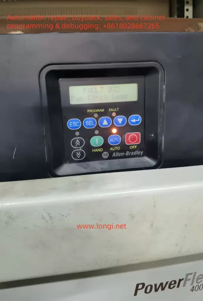
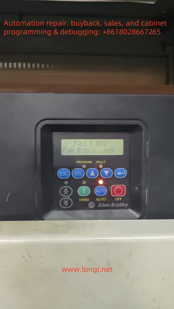
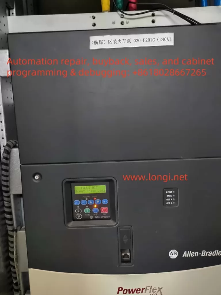
Among the numerous fault codes of the PowerFlex 400, FAULT 017 (Input Phase Loss) often signifies a detected imbalance or loss of phase in the drive’s three-phase input power supply. In essence, the drive will trigger this alarm if one of the three-phase voltages is missing, or if the voltage imbalance exceeds the permissible threshold. Once triggered, the drive will shut down output to protect the power module—i.e., the rectifier, DC bus, and inverter section—from further damage.

From an application standpoint, fans and pumps commonly present large rotational inertia and high startup currents. If system voltage fluctuations are not well controlled, or if the power grid experiences significant swings, the drive is more likely to perceive an “input phase loss.” Furthermore, many users install fuses or circuit breakers upstream to protect the drive; a single blown fuse or faulty breaker contact in one phase can also cause this fault. Thus, FAULT 017 is not an isolated problem but rather a comprehensive alarm related to external power supply quality, the operational state of the load, and the health of the drive itself.


fault 017

II. Causes and Underlying Principles

  1. Line-Side Phase Loss or Severe Voltage Drop
    • In a three-phase circuit, if one fuse is blown, a circuit breaker trips on a single phase, or if a connection terminal is badly loosened, the drive might only receive two phases (or even one phase). Consequently, the rectifier section cannot create a balanced DC bus voltage, triggering the phase-loss alarm.
    • Large, sudden dips in voltage (caused by unexpected loading, inadequate transformer capacity, etc.) can also be interpreted by the drive as “lost input phase.”
  2. Incorrect Fuse or Circuit Breaker Rating
    • If the chosen fuse/circuit breaker is undersized, or not matched to the nameplate specifications of the drive, the high inrush current when starting may cause one fuse to blow. Alternatively, continuous operation near or above rated limits can blow fuses in a single phase, leading to a phase loss alarm.
  3. Defective Contactors or Loose Input Terminals
    • In industrial settings, loose terminal screws, oxidation, and contactor burn marks are quite common. These can cause abnormal current flow in one phase, resulting in voltage imbalance and triggering the alarm.
  4. Malfunction of the Drive’s Internal Rectifier or Detection Circuit
    • Damage to the drive’s internal rectifier bridge, DC bus, or current detection modules—whether caused by overvoltage spikes or component aging—can lead the drive to incorrectly (or correctly) identify a phase loss. If external measurement confirms normal supply voltage, yet the fault persists, internal hardware failure is likely.

III. On-Site Troubleshooting Approach

  1. Safe Shutdown and Visual Inspection
    • Always power off the system and wait at least three minutes before any inspection, giving sufficient time for internal high-voltage capacitors to discharge and ensuring safety. Check the drive’s cooling channels, enclosure, and cable terminals for signs of burn, overheating, or odor. If abnormalities are observed, the drive casing may need to be opened for a deeper inspection of internal components.
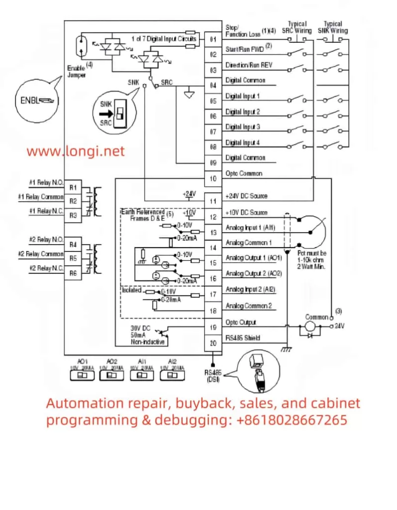
  2. Measuring Three-Phase Input Voltage
    • Use a multimeter or clamp meter to measure voltages at R/L1, S/L2, T/L3 and check whether they are in the correct phase-to-phase range (normally ±10% of the drive rating). If one phase has no voltage or is significantly lower than the other two, focus on that line’s fuse, circuit breaker, or input terminal first.
  3. Fuse and Circuit Breaker Checks
    • Reference the standard fuse or breaker sizing recommended in the drive manual to ensure proper matching. If a fuse is found to be blown or a breaker has tripped on one phase, replace it and investigate the cause (overload or short circuit).
    • Confirm the breaker has not partially tripped, leaving only two phases powered.
  4. Inspection of Contactors and Terminal Tightness
    • In systems with contactor switching or star-delta transition, worn or pitted contacts can cause open-phase conditions. Examine all contacts with a meter to ensure they behave consistently.
    • Tighten all terminal screws on the drive input; vibration or temperature changes can loosen them over time.
  5. Re-energize and Reset Fault
    • After external electrical issues are remedied, reapply power to the drive and see if the fault resets automatically or if a manual reset is required (consult the drive’s manual in Chapter 4, “Fault Handling”). If the fault remains, the drive may have an internal hardware failure.

Physical image of Powerflex 400

IV. Root Cause Analysis and Countermeasures

  1. Poor Power Supply Quality
    • Some plants have large loads starting or stopping simultaneously, causing dramatic voltage dips or fluctuations. Consider adding a line reactor or isolation transformer ahead of the drive to buffer against such interference. Where possible, upgrading network capacity or reducing high inrush loads can also mitigate phase-loss alarms.
  2. Aging Components or Improper Ratings
    • If slow-blow fuses are unsuited for the motor startup characteristics, or if circuit breakers or contactors are poorly rated, single-phase fuse blowing and contact failures may occur frequently. In heavily used fan or pump systems, selecting protective devices properly rated for maximum operational current is crucial.
  3. Site Vibration and High-Temperature Environments
    • Fans and pumps often operate in areas subject to vibration and temperature swings. Loose screws and increased contact resistance are common. Regular inspection schedules and using anti-vibration measures, such as thread-locking compounds on terminal screws, can improve connection reliability.
  4. Internal Component Damage
    • Once external phase-loss causes are ruled out and the fault persists, open the casing to check for damage on the rectifier bridge, DC bus, or sensor board. Any burn marks, bulged capacitors, or cracked circuit traces may indicate the root failure. In such cases, a specialist or authorized service should handle repairs or replacements.

V. Fault Management and Maintenance Steps

  1. Emergency Measures
    • If production needs to resume quickly after verifying balanced three-phase supply, attempt to reset or re-power the drive to see if the alarm disappears. This could indicate only a temporary fault.
    • If the fault cannot be cleared, temporarily switch the motor to run at line frequency (assuming the motor and process allow direct-on-line starts) to maintain production. Note that this bypasses the benefits of variable speed control, and starting current may spike significantly.
  2. Long-Term Solutions
    • Following the guidelines in the drive manual (Sections 1-5, 1-6 on input power considerations), add a suitable line reactor or EMI filter to increase the drive’s immunity to supply disturbances.
    • If a fuse, breaker, or contactor is mismatched, replace or upgrade it per the drive’s power specifications.
    • Conduct regular inspections of both the drive and its upstream components. For demanding fan/pump environments, shorten the service interval accordingly.
  3. Testing Hardware Components
    • If an internal failure is suspected, test the rectifier module or filter capacitors for short, open circuit, or performance degradation. Checking the driver board and DC bus voltage sensors thoroughly is advisable.
    • Replace damaged modules or send the drive for professional repair as needed. After repair, test the drive under no-load conditions, ensuring the fault does not recur, then reintroduce the motor load for final verification.

VI. Conclusion

PowerFlex 400 series drives are celebrated for their reliability and versatility, but under harsh or improperly maintained conditions, FAULT 017 (Input Phase Loss) may still occur. Essentially, this fault indicates a missing or unbalanced three-phase input supply. The root cause might be an external breaker or fuse issue, a loose terminal, or damage within the drive’s rectifier or detection circuitry. Operators should first confirm that the external supply is reliable and properly balanced, then troubleshoot and service drive components if necessary. Avoiding a hasty replacement of the drive without investigating the power system’s hidden risks is also key.

For routine maintenance and prevention, pay close attention to line cable connections, proper fuse ratings, and sudden system surges. When justified, install line reactors or EMI filters and maintain inspection logs. Only by thoroughly addressing the underlying causes can you reduce the frequency of FAULT 017, thereby extending the life of the drive and enhancing production efficiency.

In short, FAULT 017 is not merely a problem internal to the drive—it reflects a combined effect of input power and load conditions. Both short-term fixes and long-term measures require checking power supply, protective components, and the drive itself. A full understanding of the alarm’s meaning and trigger logic empowers you to tackle it effectively, ensuring stable operation of your PowerFlex 400 drive in complex industrial environments.

Posted on Leave a comment

From “X06 Not Running” to an In-depth Understanding of PowerFlex 750 Drive Ports and Fault Diagnosis

In the field of industrial automation, the PowerFlex 750 series drives by Rockwell Automation are highly regarded for their flexibility, scalability, and rich functionalities. However, precisely because these drives offer numerous optional modules and communication methods, certain fault messages can appear in ways that seem puzzling. Many engineers, for instance, encounter an alert such as “X06 Not Running” or “Port x06 Not Running,” only to open the drive’s enclosure and discover—much to their surprise—that there is no label or port physically marked “X6.” This article aims to address that very phenomenon by clarifying the relationship between logical ports and physical slots. We will delve into why the “X06 Not Running” error occurs, how to troubleshoot it systematically, and—given the possible scenario of drives connected in parallel—how to arrive at practical solutions.


I. Why Can’t We Find “X6” on the Hardware?

1. Logical Ports vs. Physical Slots

In PowerFlex 750 series drives, the term “Port” represents not just a visible hardware interface, but a logical address assigned by the drive firmware. For example, Port 0 usually refers to the Main Control Board, Ports 1 and 2 might be for the front-panel Human Interface Module (HIM) or DPI devices, while Port 6 typically corresponds to the optional module slot, often labeled “Slot C” or “Option Slot 3.” When the drive reports “X06 Not Running” or “Port 6 Adapter Fault,” it is referring to logical Port 6, indicating a module at that position is malfunctioning, rather than some physical connector marked “X6.”

Device conflict, X port X06 is not running

2. Physical Labels Often Appear as “Slot C” or “Option Slot 3”

From a design standpoint, to accommodate various expansion needs in a limited space, the main control board usually includes three to four optional module slots for installing communication adapters, I/O extension cards, or feedback modules. These slots are often labeled “Slot A/B/C” or “Option Slot 1/2/3.” At the software level, the drive maps these slots to Ports 4, 5, 6, and so forth. The main objective is to unify the management of internal and external resources: logical port numbering handles internal data flow, whereas hardware slot labels facilitate on-site module installation and removal.

Consequently, you may see a physical slot labeled “Slot C” or “Option 3” on the drive but not find any silkscreen or marking of “X6” or “Port 6.” If the module in this slot malfunctions or if the slot configuration is incorrect, the system will display an alarm specifically mentioning “Port 6,” leading to a mismatch between how the hardware is labeled and how the firmware identifies it.


II. Possible Causes of the “X06 Not Running” Error

When you see “X06 Not Running” or “Port 6 Not Running,” it generally indicates that the expansion module at Port 6 is in an abnormal state. Common causes include:

  1. Uninstalled or Empty Slot, Yet Configured The drive might be configured to have a communication or I/O module at Port 6, but the slot is physically empty. Consequently, the system cannot detect the module and raises the error indicating that Port 6 is not running.
  2. Improper Module Installation or Hardware Failure If the slot does have an expansion module (for example, a 20-750-ENETR Ethernet adapter or a 20-750-DNET DeviceNet adapter) but the module is loose, has poor contact, or is damaged, the drive will perceive it as disconnected. Hardware issues can include defective internal components, as well as firmware incompatibilities.
  3. Network or Communication Configuration Conflicts For communication modules, if there is a duplicate network address, a mismatched baud rate, or a failure on the fieldbus (cabling short, bus power issues, and so on), the module cannot communicate properly with the drive’s main board. As a result, the drive may show “Port 6 Not Running” or “Comm Loss.”
  4. Firmware and Configuration Incompatibility When the drive’s firmware version differs substantially from that of the module, the drive might not be able to fully recognize the module’s functionality or might detect an invalid configuration. An older drive firmware may not support certain features in a new adapter.
  5. Parallel System Configuration Errors In systems where multiple PowerFlex 750 drives are connected in parallel to drive a high-power motor or share a common bus, Port 6 is often used for inter-drive synchronization or redundancy communication. An addressing conflict or a misconfiguration of master/slave roles can cause one of the drives to report a port error.

Physical image of Powerflex 750

III. Why You Can’t Find “X6” After Disassembling the Drive

Many users, upon seeing the fault code, first attempt a physical inspection. However, after opening the enclosure, they notice that none of the slot labels match “Port 6,” and they don’t see anything labeled “X6.” This is likely due to the following factors:

  1. Chassis Labels Only Read “Slot C” The PowerFlex series generally uses letters or numbers to identify slot order, and not a marking such as “X6” or “Port 6.”
  2. Ports Are Assigned at the Software Level Port 6, Port 5, Port 4, etc., are naming conventions in the drive’s internal DPI or system bus rather than user-facing hardware markings.
  3. Slot Position May Be Obscured by a Metal Bracket or Circuit Board On higher frame sizes (Frame 8 and above) or particular designs, there may be layered sub-boards or shielding that hides the slot labels. You might need to remove additional parts to locate “Slot C.”
  4. Empty or Damaged Slots If the slot meant for Port 6 is truly empty or if the module has fallen out or is damaged, there is no direct label for the user to see.

IV. How to Identify and Locate Port 6

  1. Refer to the Official Installation Manual’s “Slot Layout Diagram” Rockwell documentation typically provides a layout diagram for these optional slots, clearly explaining how “Slot A = Port 4,” “Slot B = Port 5,” “Slot C = Port 6.” Comparing the manual’s diagram with the physical drive helps pinpoint the slot corresponding to Port 6.
  2. Check Module Information Using HIM or Software By accessing the parameters in the front-panel HIM or by using DriveTools or Studio 5000 software, you can view “Module Info” or “Adapter Info,” where each port’s installed hardware is displayed. If Port 6 shows a communication adapter model, that indicates it is mounted in “Slot C” or “Option Slot 3” physically.
  3. Physical Observation of the Slot Layout Most PowerFlex 753/755 drives have three side-by-side optional slots on or near the main control board, labeled A, B, and C, or Option 1, 2, and 3. If you see a module in Slot C, that module is the physical carrier for Port 6 from the firmware’s perspective.
  4. Cross-Check with the Drive’s Fault Log The HIM or the drive configuration software can display a fault queue. If there are repeated references to “Port 6 Adapter Fault” or “Port 6 Comm Loss,” that indicates issues specifically related to the module in Slot C.

Powerflex 750 internal structure and terminal diagram

V. Steps to Resolve the “X06 Not Running” Error

  1. Confirm Whether Port 6 Module Is Needed
    • If the slot is supposed to be empty, disable or remove the configuration referencing Port 6 in the drive parameters.
    • If it does require a module, check whether the module is missing or physically damaged.
  2. Examine Physical Installation and Connections
    • Power down the drive, remove the module, inspect for bent pins or contamination, then re-seat it firmly.
    • For communication modules, make sure the bus cables and terminators are set up properly, and that bus power is available.
  3. Diagnose Network Conflicts
    • For DeviceNet or other fieldbus protocols, ensure all device addresses are unique and the baud rate matches.
    • In parallel systems, verify that each drive’s address and roles (master/slave) do not conflict.
  4. Check Drive and Module Firmware Compatibility
    • Certain older drives might not recognize newer modules. Consult the official Rockwell documentation and release notes, and consider firmware updates that support the required module features.
  5. Factory Reset or Reconfigure If Necessary
    • If hardware is intact but the issue persists, try restoring Port 6 parameters to defaults and then reapply correct settings. This step can help resolve initialization failures caused by parameter corruption.

VI. Avoiding Port Faults in Parallel Applications

When multiple PowerFlex 750 drives run in parallel to drive a high-power motor or share a common bus, they often rely on inter-drive communication and synchronization. Common issues leading to “X06 Not Running” in such scenarios include:

  • Address Conflicts: For instance, if each drive has a DeviceNet module with the same node address, then some modules will drop offline.
  • Improper N-1 Redundancy Configuration: If one drive is designated as the master and another is the follower, a misconfigured follower may cause the master drive to detect that Port 6 is down, stopping the entire system.
  • Missing Synchronization Signals: If the optical fiber or sync cables between parallel drives are disconnected, the drive can report a fault for the relevant port.

To prevent such faults, proper planning is essential from the outset—assigning unique addresses, defining consistent master/slave roles, and thoroughly testing each drive individually, then in collective operation. Regularly monitoring network status and each drive’s port modules will help you detect potential problems early.


VII. Conclusion

The message “X06 Not Running” may initially seem mysterious or perplexing, but in reality, it reflects the PowerFlex 750 drive’s internal scheme for managing expansion modules via logical ports. The drive firmware assigns port numbers to identify each module; as soon as a particular module is missing, malfunctioning, or misconfigured, the drive displays an alert naming that logical port—for example, Port 6.
Effective troubleshooting requires a solid understanding of how hardware slots (such as Slot C) correspond to these logical ports, along with targeted use of official documentation or diagnostic tools. In multi-drive, parallel systems, you must also pay close attention to address settings, role assignments, and synchronization signals to ensure each drive operates in harmony.
By applying the concepts outlined here, you can significantly reduce downtime and confusion related to “X06 Not Running” or similarly cryptic errors. This knowledge also lays a robust foundation for future maintenance and potential system expansions, where familiarity with port-slot logic and network coordination becomes even more valuable.

Posted on Leave a comment

User Guide for the Rockwell PowerFlex 400 Series Inverter Manual

The Rockwell (Allen-Bradley) PowerFlex 400 series inverter is a powerful industrial control device designed for applications such as fans and pumps, offering flexibility, ease of configuration, and high reliability. This article, based on the PowerFlex 400 series manual, provides a detailed guide on its operation panel functions, external terminal control methods, and fault code troubleshooting. It aims to help users fully grasp the skills needed for operating and maintaining the equipment. This guide is clear, logical, and comprehensive, suitable for engineers, technicians, and field operators.


I. Introduction to the Operation Panel Functions

The PowerFlex 400 series inverter is equipped with a user-friendly Human Interface Module (HIM), which allows parameter configuration, status monitoring, and fault diagnosis via buttons and a display screen. Below is a detailed explanation of its main functions and operation steps.

Powerflex 400 in operation

1. Panel Layout and Button Functions

The operation panel is the core interface for user interaction with the inverter. Its layout includes:

  • LCD Display: Shows running frequency, parameter numbers, fault codes, etc.
  • Arrow Keys (Up, Down, Left, Right): For menu navigation and parameter adjustment.
  • Enter Key: Confirms selections or saves settings.
  • Esc Key: Returns to the previous menu or cancels operations.
  • Start/Stop Keys: Starts or stops the inverter in manual mode (must be enabled via parameters).

Familiarity with these buttons allows users to easily navigate menus and complete configurations.

2. Copying Parameters to Another Inverter

The PowerFlex 400 supports parameter copying, making it easy to replicate settings across multiple devices. Follow these steps:

  • Step 1: On the source inverter’s HIM panel, enter the “Parameter” menu.
  • Step 2: Select “Copy to HIM” to save parameters to the panel’s memory.
  • Step 3: Remove the HIM panel from the source inverter and insert it into the target inverter.
  • Step 4: On the target inverter, enter the “Parameter” menu and select “Copy from HIM.”
  • Step 5: Confirm to load the parameters onto the target inverter.
  • Note: Both inverters must be of the same model and firmware version to avoid compatibility issues.

3. Initializing Parameter Settings

To reset the inverter to factory settings, follow these steps:

  • Step 1: Enter the “Parameter” menu and locate parameter P041 (Reset to Defaults).
  • Step 2: Set P041 to “1” (Reset) and press Enter to confirm.
  • Step 3: Wait for the inverter to complete the reset; the display will indicate success.
  • Note: Initialization erases all user settings; it is recommended to back up parameters first.

4. Setting Password and Parameter Access Restrictions

To protect parameters from unauthorized changes, the PowerFlex 400 offers a password feature:

  • Step 1: Enter the “Parameter” menu and find parameter P042 (Password).
  • Step 2: Enter a four-digit password (e.g., “1234”) and press Enter to save.
  • Step 3: Set parameter P043 (Password Enable) to “1” to activate password protection.
  • Step 4: In parameter P044 (Access Level), select the access level:
  • “0”: Basic (limited to common parameters).
  • “1”: Advanced (access to all parameters).
  • Note: If the password is forgotten, contact technical support or use specialized tools to unlock it.

II. External Terminal Control and Speed Regulation

The PowerFlex 400 supports forward/reverse control and frequency adjustment via external terminals, ideal for scenarios requiring manual switches or potentiometer control. Below are the wiring and parameter configuration methods.

1. External Terminal Forward/Reverse Control

To control start, stop, and direction via external switches, follow this wiring and setup:

  • Wiring Instructions:
  • Terminal 11 (Digital In 1): Connect to one end of the start/stop switch.
  • Terminal 12 (Digital In 2): Connect to the direction selection switch (forward/reverse).
  • Terminal 01 (Common): Common terminal, connect to the other end of the switches.
  • Parameter Settings:
  • P036 (Start Source): Set to “2” (2-Wire Control) to enable two-wire control mode.
  • P037 (Stop Mode): Set to “1” (Ramp) for smooth stopping.
  • A051 (Digital In1 Sel): Set to “4” (Run) to define terminal 11 as run control.
  • A052 (Digital In2 Sel): Set to “6” (Direction) to define terminal 12 as direction control.
  • Operation Verification: Close terminal 11 to start the inverter; switch terminal 12 to control direction.

2. External Potentiometer for Frequency Control

To adjust the operating frequency with an external potentiometer, follow this wiring and configuration:

  • Wiring Instructions:
  • Terminal 15 (Analog In 1+): Connect to the potentiometer’s wiper (signal output).
  • Terminal 16 (Analog In 1-): Connect to the potentiometer’s low potential end.
  • Terminal 17 (Analog In Common): Connect to the potentiometer’s high potential end (usually 10V supply).
  • Parameter Settings:
  • P038 (Speed Reference): Set to “2” (Analog In 1) to select analog input 1 as the frequency reference.
  • A065 (Analog In 1 Hi): Set to the maximum frequency (e.g., 60 Hz), corresponding to the potentiometer’s maximum.
  • A066 (Analog In 1 Lo): Set to the minimum frequency (e.g., 0 Hz), corresponding to the potentiometer’s minimum.
  • Operation Verification: Rotate the potentiometer to observe smooth frequency changes from minimum to maximum.

With these configurations, users can achieve external switch control for start/stop and direction, while precisely adjusting speed with a potentiometer.


PowerFlex400 Control Wiring Diagram

III. Fault Codes and Their Handling

The PowerFlex 400 may trigger faults due to power, load, or environmental issues. Understanding fault codes and their solutions is crucial. Below are common fault codes, their meanings, and troubleshooting steps.

1. Common Fault Codes and Meanings

  • F005 (OverVoltage)
  • Meaning: DC bus voltage exceeds the allowable range, often due to rapid deceleration or power fluctuations.
  • Solution:
    1. Check if the input power voltage is too high.
    2. Extend the deceleration time in parameter P039 (Decel Time).
    3. If frequent, consider installing a braking resistor.
  • F012 (UnderVoltage)
  • Meaning: DC bus voltage is below normal, possibly due to power interruption or poor wiring.
  • Solution:
    1. Ensure the input power is stable and within the rated range.
    2. Check for loose power connections.
  • F032 (Fan Feedback Loss)
  • Meaning: Cooling fan is not working or feedback signal is abnormal.
  • Solution:
    1. Check for foreign objects blocking the fan.
    2. Ensure the fan power cable is properly connected.
    3. Replace the fan if damaged.
  • F048 (Params Defaulted)
  • Meaning: Parameters have been reset to factory defaults.
  • Solution: Reconfigure necessary parameters; consider backing up settings.
  • F081 (Comm Loss)
  • Meaning: Communication with the host or network is lost.
  • Solution:
    1. Check communication cables and connectors.
    2. Verify parameter A103 (Comm Format) is set correctly.

2. General Fault Handling Steps

  • Step 1: Record the fault code and operating conditions at the time.
  • Step 2: Refer to the manual’s fault code table to analyze possible causes.
  • Step 3: Check power, wiring, and load conditions to rule out external factors.
  • Step 4: Press the “Fault Reset” button to attempt a reset; resume operation if successful.
  • Step 5: If the fault recurs, contact Rockwell technical support for further assistance.

Conclusion

The Rockwell PowerFlex 400 series inverter, with its outstanding performance and flexible operation, is a preferred choice in industrial settings. This article covers the operation panel functions, external terminal control, and fault code handling, providing a comprehensive user guide. By mastering panel operations, users can efficiently configure parameters; through external terminal setups, they can achieve flexible control schemes; and with fault code analysis, they can quickly resolve issues to ensure stable operation. This guide aims to offer practical support, enhancing users’ efficiency and maintenance capabilities with the equipment.

Posted on Leave a comment

Analysis and Solution of F 032 Fault in Rockwell PowerFlex 400 Series Inverter


The Rockwell (Allen-Bradley) PowerFlex 400 series inverter is a widely used, high-performance device in industrial automation, valued for its stability and reliability. However, during prolonged operation, it may encounter faults, one of which is the F 032 fault, known as Fan Feedback Loss. This article analyzes this fault in detail—its meaning, causes, on-site troubleshooting steps, and repair methods—offering clear guidance for field engineers to restore equipment operation efficiently.


What the F 032 Fault Means and Why It Happens

Meaning of the Fault

The F 032 fault code indicates Fan Feedback Loss, a common issue in Frame E and F models (higher power units) of the PowerFlex 400 series. These models feature a cooling fan feedback monitoring system. When the inverter cannot detect the fan’s normal operation, it triggers this fault and shuts down to prevent overheating damage.

f032

How It Occurs

The inverter generates significant heat during power conversion, and the cooling fan is essential to keep internal components (like IGBT modules and capacitors) at safe temperatures. In Frame E and F models, the fan sends a feedback signal to the inverter’s control system to confirm it’s working. If this signal is lost—due to fan failure, wiring issues, or control circuit problems—the F 032 fault is activated.

Possible Causes:

  • Fan Mechanical Failure: Blocked blades, damaged motor, or seized bearings.
  • Power/Circuit Problems: Open or short circuits, or loose power supply connections.
  • Feedback Signal Issues: Disconnected, broken, or faulty signal lines or control board circuits.
  • Environmental Factors: Excessive heat or dust affecting fan performance.

Why It Matters

The F 032 fault is a self-protection mechanism. Without proper cooling, sensitive components could overheat, leading to equipment failure. By stopping operation, the inverter prevents damage, prioritizing long-term reliability over temporary production continuity.


On-Site Troubleshooting Steps

When an F 032 fault appears, follow these steps to diagnose and fix it quickly, minimizing downtime:

  1. Check Fan Operation
  • Action: Power off the inverter, open the panel, and check if the fan spins.
  • Steps: Remove dust or debris from blades; manually spin the fan to detect jams or resistance.
  • Goal: Rule out mechanical issues.
  1. Inspect Power and Control Circuits
  • Action: Examine the fan’s power and signal line connections.
  • Steps: Use a multimeter to verify voltage at the fan’s power terminal; check for circuit breaks or shorts.
  • Goal: Ensure power delivery isn’t the issue.
  1. Verify Feedback Signal Lines
  • Action: Check the connection between the fan’s feedback line and the control board.
  • Steps: Confirm the line isn’t loose or broken; test continuity with a multimeter if possible.
  • Goal: Fix signal transmission problems.
  1. Reset and Test
  • Action: Reset the fault via the panel’s “FAULT RESET” button or programming mode.
  • Steps: Restart the inverter and monitor if the fault recurs; continue operation if cleared.
  • Goal: Confirm if it was a temporary glitch.
  1. Review Parameter Settings
  • Action: Access programming mode to check fan monitoring parameters (e.g., P040).
  • Steps: Verify the function is enabled and settings are correct.
  • Goal: Eliminate false alarms from misconfiguration.
  1. Assess Environmental Conditions
  • Action: Evaluate the inverter’s surroundings.
  • Steps: Clean the heat sink; ensure ambient temperature is within 0-50°C.
  • Goal: Address environmental triggers.

Most F 032 faults can be resolved with these steps. If the issue persists, deeper repairs are needed.


Repair Methods When On-Site Fixes Fail

If troubleshooting doesn’t work, the problem may involve hardware damage. Here’s how to proceed:

  1. Disassemble the Inverter
  • Action: Power off, discharge residual voltage, and remove the casing.
  • Tips: Follow safety protocols; note disassembly steps for reassembly.
  • Tools: Screwdriver, multimeter.
  1. Examine Fan and Circuits
  • Action: Inspect the fan, power lines, control lines, and feedback lines.
  • Steps: Test power supply voltage; look for burns or breaks in circuits.
  • Fix: Repair or replace damaged parts; test the fan next if power is fine.
  1. Test the Fan Independently
  • Action: Connect the fan to a separate power source.
  • Steps: Check if it spins; replace it if it doesn’t (use a matching model).
  • Tips: Ensure compatibility with the original fan.
  1. Check the Control Board
  • Action: Inspect the main control board or fan control circuit.
  • Steps:
    • Look for burned components or loose solder joints.
    • Test feedback signal input with a multimeter.
    • Identify issues like damaged chips or connectors.
  • Fix: Re-solder joints; replace faulty components; consider board replacement if damage is severe.
  1. Reassemble and Verify
  • Action: Reassemble, power on, and test.
  • Steps: Confirm fan operation and fault clearance; monitor cooling performance.
  • Goal: Ensure the repair worked.

powerflex 400

Preventing Future F 032 Faults

To minimize recurrence:

  • Routine Cleaning: Clear dust from the inverter and fan every three months.
  • Wiring Checks: Regularly inspect power and signal line connections.
  • Ventilation: Keep the installation area well-ventilated and within temperature limits.

Conclusion

The F 032 fault in the PowerFlex 400 series inverter is a vital alert tied to fan failure, designed to prevent overheating damage. By understanding its causes and following structured on-site troubleshooting, engineers can often resolve it quickly. For persistent issues, detailed repairs targeting the fan or control board are effective. Combined with preventive maintenance, these steps ensure equipment reliability and support uninterrupted industrial operations.


Posted on Leave a comment

User Manual Guide for Rockwell PowerFlex 400 Series Variable Frequency Drive

I. Function Introduction and Parameter Setting of the Operation Panel (Numeric Keypad)

The PowerFlex 400 Series Variable Frequency Drive (VFD) is equipped with an intuitive operation panel. Users can easily complete parameter settings, monitor operating status, and perform fault diagnosis through the numeric keypad. The main keys on the operation panel include the Increment Key, Decrement Key, PRG Function/Data Toggle Key, STOP Key, SET/Data Confirmation Key, and MF.K/Multi-Function Key.

Powerflex 400 numeric keypad function diagram

Password Setting and Parameter Modification Restriction:

After entering the parameter editing mode, users can set a password to restrict parameter modifications by selecting a specific parameter (e.g., P042). Once the password is set, unauthorized users will be unable to change the protected parameters.

To eliminate the password, simply set the password parameter (P042) to 0 and save the changes.

Restoring Factory Default Parameters:

With the VFD in the stopped state, press the programming key to enter the menu, select the F0.13 function to restore parameters, change the current value to 2, and press the confirmation key to save. This will restore all parameters to their factory defaults, eliminating any user-defined settings.

II. External Terminal Control for Forward/Reverse Operation and Potentiometer Speed Adjustment Settings

Forward/Reverse Control:

The PowerFlex 400 Series VFD supports forward/reverse control of the motor through external terminals. The specific setting parameters are T051 to T054, which define the functions of the multi-function input terminals. For example, set T051 to 1 (forward operation) and T052 to 2 (reverse operation), and then connect the corresponding external switches or relays to the respective input terminals to achieve forward/reverse control of the motor.

Potentiometer Speed Adjustment:

Potentiometer speed adjustment is a common analog speed control method. First, configure the VFD’s analog input terminals (e.g., AI1 or AI2) to accept voltage or current signals from the potentiometer. This can be achieved by setting parameters T069 or T073 to select the corresponding input range and signal type (e.g., 0-10V voltage or 4-20mA current). When wiring, connect the sliding end of the potentiometer to the VFD’s analog input terminal and the fixed ends to the power supply and ground respectively.

Powerflex 400 External Terminal Control Diagram

III. Analysis of Fault Codes and Solutions

The PowerFlex 400 Series VFD features comprehensive fault diagnosis capabilities. When a fault occurs, the VFD displays the corresponding fault code. Below are some common fault codes, their meanings, and solutions:

  • F36: Output Overcurrent. Possible causes include motor overload, output short circuit, or improper parameter settings. Solutions include checking motor load, inspecting the output circuit, and adjusting relevant parameters (e.g., P033 motor overload current setting).
  • Drive-HIM: Drive Alarm. Typically caused by EEPROM checksum errors. Solutions include power cycling or replacing the HIM module.
  • F22: Drive Reset Fault. May occur during power-up or operation. The solution is to check the correctness of the wiring, especially the connections at the TB2 terminal.
  • F32: EEPROM Fault. May be due to corrupted EEPROM data or inability to program valid data. Solutions include checking the connection between the main control board and the power board, resetting to default parameters, and power cycling.

IV. Summary

The Rockwell PowerFlex 400 Series VFD, with its powerful functions, flexible configuration, and reliable performance, is widely used in the field of industrial automation. Through the introduction in this article, users can better understand and master the functions of the VFD’s operation panel, external terminal control settings, fault diagnosis, and solutions, thereby ensuring safe and efficient operation of the VFD. Whether for users who are new to VFDs or experienced engineers, this user manual provides valuable information and practical operating tips. In practical applications, it is recommended that users configure VFD parameters based on specific application scenarios and needs, and regularly inspect and maintain the VFD to extend its service life and improve production efficiency.

Posted on Leave a comment

PowerFlex 750 Series AC Drive User Guide

PowerFlex 750 Series AC Drive User Guide

1. Operation Panel (Keypad) Usage

The operation panel (keypad) of the PowerFlex 750 series AC drive serves as the primary interface for user interaction. It allows users to navigate menus, set parameters, and view status information.

Navigation and Selection: Use the arrow keys to navigate through menus and the “Select” button to enter specific settings or parameter editing mode.

Parameter Editing: In edit mode, enter or adjust parameter values using the numeric keys or arrow keys.

Saving and Exiting: After making changes, use the “Save” button to save modifications and the “Exit” button to return to the previous menu or the main interface.

Status Viewing: Select the appropriate option from the menu to view the drive’s output frequency, current, voltage, fault codes, and other status information.

Rockwell Powerflex 755 Series VFD Status Indicator Light Description

2. Open-Loop V/F Control Parameter Settings

In open-loop V/F (Volts per Hertz) control mode, the drive regulates the motor speed by adjusting the ratio between the output voltage and frequency. Here are guidelines for setting key parameters:

  • P35 (Motor Control Mode): Set to “V/Hz” mode to enable open-loop V/F control.
  • P25 (Motor Nameplate Voltage): Enter the motor’s rated voltage.
  • P27 (Motor Nameplate Frequency): Input the motor’s rated frequency.
  • P60 (V/F Curve Settings): Adjust the V/F curve as needed to optimize motor performance.
  • P520/P521 (Maximum Forward/Reverse Speed): Set the maximum operating frequency limits for the motor.
I/O Wiring Diagram for Rockwell Powerflex 755 Series VFD

3. Terminal Start and Potentiometer Speed Adjustment Wiring and Parameter Settings

Wiring Instructions:

  • Main Power and Control Power Connection: Connect the three-phase main power and (if required) control power as specified in the manual.
  • Motor Connection: Wire the motor’s three-phase leads to the U, V, W output terminals.
  • Start/Stop Terminal Connection: Connect the contacts of the external start/stop buttons to the drive’s DI (Digital Input) terminals and configure the related parameters.
  • Potentiometer Speed Adjustment Connection: Connect the potentiometer’s wiper to the AI (Analog Input) terminal for speed regulation.

Parameter Settings:

  • Digital Input Configuration: Configure relevant parameters to assign DI terminals for start/stop functions.
  • Analog Input Configuration: Ensure AI terminals are set as the speed reference source and adjust the input range to match the potentiometer’s output range.
  • Speed Reference Selection: Specify the analog input as the source for speed references in the parameters.

4. Fault Code Analysis and Troubleshooting Summary

According to the fault code list provided in the manual (pages 316-323, fault numbers 0-155), here are summaries of a few common faults, their possible causes, and troubleshooting methods:

  • F001: Overcurrent Protection. Check for motor overload, stable power supply voltage, and short circuits in the output circuit.
  • F002: Overvoltage Protection. Verify that the input voltage is within the allowed range and consider installing a voltage stabilizer or adjusting the input filter.
  • F003: Undervoltage Protection. Check if the power supply voltage is too low and confirm correct power line connections.
  • F004: Overheat Protection. Inspect the drive and motor cooling, clean dust from the heat sink, and ensure proper ventilation.
  • F005: Communication Failure. Check communication line connections, verify correct communication parameter settings (including baud rate, data bits, etc.).

Please note, the above fault codes are examples, and specific fault codes and their solutions should be referenced directly from the manual.

5. General Troubleshooting Steps

  • Check Fault Code: Read and record the fault code on the operation panel.
  • Consult the Manual: Look up the corresponding fault description, possible causes, and solutions in the manual.
  • Perform Preliminary Checks: Examine power sources, motors, communication lines, etc.
  • Reset the Drive: If initial checks reveal no issues, attempt to reset the drive to clear temporary faults.
  • Advanced Diagnostics: If problems persist, professional tools may be