Posted on Leave a comment

A Deep Dive into the Pro-face SP-5B10 Module: The “Brain” Behind the Touchscreen and the Key to System Operation


I. Introduction

In modern industrial automation, the Human Machine Interface (HMI) plays a critical role in boosting production efficiency and ensuring operational safety. Pro-face, a Japanese brand well-known in the HMI field, has adopted a modular design in its SP series touchscreens: users can freely choose different display sizes and pair them with the appropriate “box modules” to handle complex control tasks. Thanks to this design, the Pro-face SP series is widely used across industries such as machinery manufacturing, electronics assembly, pharmaceuticals, and food processing.

Despite its popularity, many users have questions when disassembling or maintaining an SP series touchscreen. Specifically, they may wonder about the module located on the back that looks like a “power box” or “processor unit.” What function does it serve? If you remove this module, can the display still operate as long as it is powered? This article will take an in-depth look at the Pro-face SP-5B10 (PFXSP5B10) box module—its features and importance, how it interacts with the display module, and whether or not the touchscreen can still function normally once the module is removed.


II. Overview of the Pro-face SP-5B10 Module

Module SP-5B10

1. Module Positioning: The Core Processing Unit of the HMI

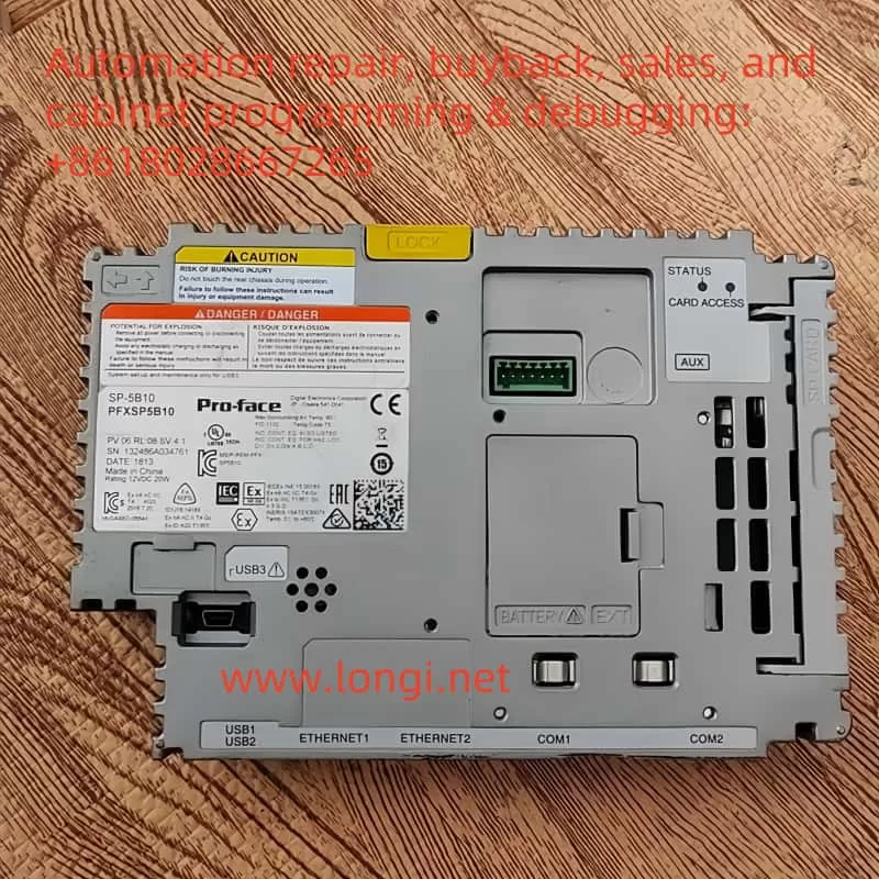
The Pro-face SP-5B10 box module (also known as the “enhanced box module” or “Power Box”) is the “brain” of the SP5000 series touchscreen system. It houses the processor, memory, and various industrial communication interfaces. Unlike a traditional, single-unit HMI device, Pro-face introduced a modular approach in the SP series by separating the display section and the processing section, referred to as the display module and the box module, respectively. As the box module, SP-5B10 is in charge of running control logic, storing project data, connecting devices via different networks, and overseeing the overall operation of the system.

2. The “Brain” for Running Business Logic and Display Screens

In practical applications, an HMI often needs to run custom programs for production lines, equipment, or processes—such as displaying workflows, monitoring real-time data, and sending or receiving control commands. These configured screens and logic programs are developed via software like GP-Pro EX and are downloaded to the box module. The SP-5B10 provides ample processing power and memory to execute these screen logics, data collection tasks, and alarm management. It then transmits the resulting display data to the display module. Essentially, without the box module’s processing and control, the HMI’s “intelligence” does not exist, and the touchscreen would be reduced to a blank display panel.

3. Data and System Software Storage

The SP-5B10 box module integrates storage features, including an SD card slot, internal flash memory, and backup battery. In more detail:

  • System Storage: Contains the HMI’s system firmware, operating system, and basic drivers needed for startup.
  • Project Data Storage: Stores project files, alarm information, recipe data, etc., that are downloaded from development software such as GP-Pro EX. This approach allows easy maintenance; for instance, if the display module needs replacing, simply removing and reattaching the box module or swapping the storage card can restore the entire application.
  • Alarm and Historical Records: Many industrial environments require the recording of alarm data and operational logs—sometimes for weeks or months. The SP-5B10’s internal flash memory or SD card meets these demands.

4. The Central Hub for Multiple Industrial Communication Interfaces

In industrial settings, an HMI commonly exchanges data with PLCs, inverters, sensors, or upper-level management systems, making diverse interfaces and protocols critical. The SP-5B10 often includes:

  • Ethernet Ports: Typically at least one or two RJ-45 ports supporting 10/100/1000 Mbps to connect PLCs, SCADA, or MES systems.
  • Serial Interfaces (COM Ports): RS-232C, RS-422/485, etc., for older PLCs and instruments still widely used.
  • USB Host/Device Ports: For connecting USB peripherals such as flash drives or barcode scanners, as well as for direct communication or program downloads from a PC.
  • Expansion Bus: Some box modules allow additional interface cards (e.g., fieldbus expansions, field I/O boards) to suit a variety of automation scenarios.

As the conduit for all external signals and data, the SP-5B10 processes information before passing it on to the display module, allowing seamless “field–HMI–network” connectivity.


III. How the SP-5B10 Works with the Display Module

1. Physical Connection: A Rear Plug-in Connector

In the Pro-face SP5000 series, the box module and display module link up via a specialized connector on the display’s rear side. The box module securely latches onto the display module through a rail or clip mechanism:

  • Power Supply: The display module connects to external power (e.g., 24 V DC) and converts it internally to power the box module, which does not require its own power input.
  • Signal Transmission: The connector transmits video signals while also carrying touch input signals and other data between the processor and display.

This modular concept makes it easy for users to replace or upgrade components. For example, if you want to switch to a larger display but keep the same box module, simply remove the original display and connect the SP-5B10 to a new, larger SP series display. Likewise, if you need higher processing performance, you can upgrade only the box module without having to swap out the entire display screen.

2. Logical Coordination: Clear Division of Labor, Integrated Operation

The SP-5B10 handles core computing, communications, and data storage, while the display module is responsible for UI presentation and touch sensing. Their cooperation can be summarized as:

  • Screen Data Transmission: The SP-5B10 runs the screen logic and sends the display content to the display module, which then renders and displays it.
  • Touch Feedback: When an operator touches a button or drags an object on the screen, the display module detects the action and relays it back to the box module for processing, which either responds or carries out related control commands.
  • System Health Management: If the box module detects high temperature or an internal fault, it can alert the display module to show warnings or shut off the backlight, ensuring safe operation of the entire system.

IV. What Happens if You Remove the SP-5B10?

Many wonder whether the front display panel can still function if the box module is taken out. The short answer is no. The SP-5B10 is not a simple add-on accessory; it is the “brain” and “heart” of the entire HMI system. Once it is removed, the display module loses its processor, memory, and communication interfaces, which means it becomes non-functional. Specifically:

  1. No Display
    Without the display data provided by the SP-5B10, the screen may only have power for the backlight (if at all) but will show no graphics or text. All HMI screens are generated by the box module, so with it removed, there is no output signal for the display panel.
  2. No Touch Operation
    Since no box module is present to read and process touch coordinates, any touch input is rendered meaningless. Typically, the screen’s coordinate signals must be sent to and interpreted by higher-level software or the OS, which runs on the SP-5B10.
  3. Loss of Data Collection and Communication
    The box module provides interfaces like serial ports, Ethernet, and USB. Removing it also removes these interfaces, and thus the touchscreen can no longer communicate with PLCs, sensors, or PCs. Effectively, all monitoring and control functions cease.
  4. Loss of System and Project Data
    The SP-5B10 stores screen projects, recipes, alarm history, and more on an SD card or in internal memory. Removing the module effectively takes away all critical data needed for system operation. The display module itself usually does not retain these files and cannot independently load the application.

Hence, removing the SP-5B10 renders the Pro-face touchscreen incapable of displaying or interacting with any functionality. The system will only resume normal operation once the box module (or a compatible alternative) is reattached and powered up.


Display screen SP-5700TP

V. Conclusion and Recommendations

In summary, the Pro-face SP-5B10 box module is an irreplaceable core component of the SP series touchscreen. It not only handles screen display and touch input processing, but also provides the storage space, communication interfaces, and expansion capabilities vital for complete HMI functionality. For engineers and maintenance personnel who rely on Pro-face HMIs for field device monitoring, data collection, and process visualization, ensuring that the box module and display module remain properly connected and functioning is crucial.

If you need a functioning display, you cannot rely solely on the screen hardware. During maintenance, if you must remove the box module, always do so with the power off and take precautions to protect the storage card and the module from static or physical damage. Bear in mind that once the SP-5B10 is removed, the touchscreen loses its central processing capability and will not operate; only by reinstalling the compatible box module and powering the system can normal functions be restored.

In essence, the SP-5B10 module is like the processor and storage system in a smartphone—without it, even the best screen is just inert “glass.” Removing it inevitably leads to loss of the original interface, disabling any touch inputs or data communications. Therefore, to ensure stable, continuous operation of Pro-face HMIs, the SP-5B10 and display module must remain tightly integrated so that the system can take full advantage of the module’s high-speed processing and multi-interface communication features, enabling better equipment monitoring and process management on the industrial floor.


Posted on Leave a comment

A Comprehensive Analysis of the “06” Code on Schneider ATV303 Inverters and How to Handle It


I. Background and Importance

Within the realm of industrial automation, frequency inverters have become indispensable for motor control. Schneider Electric’s ATV series inverters enjoy a strong reputation for reliability and versatility, making them popular in many factories and engineering projects. The ATV303, in particular, is a cost-effective model frequently used with fans, pumps, and conveyor systems. For maintenance personnel, a solid understanding of the inverter’s fault and status codes is crucial for improving production efficiency, reducing downtime, and preventing unnecessary equipment damage.

In actual usage, one may occasionally see the code “06” appear on the display panel of the ATV303 inverter. Since most real faults are labeled with an “F” prefix (e.g., F013 for motor overload or F011 for an overheat warning), many technicians might feel confused upon seeing “06”: Is it a fault code or just a normal state indicator? Is urgent shutdown and troubleshooting needed? In fact, the “06” code on the ATV303 is not a fault, but rather an indication of the Freewheel Stop state. This article provides a detailed explanation of the meaning of the “06” code, why it might appear, and how to deal with it properly so that readers can swiftly diagnose and address the situation.


--06

II. The Real Meaning of Code 06

According to the official Schneider documentation for the ATV303, any code beginning with an “F” denotes an actual fault alarm—examples include F002, F006, F013, and so on. These alarms necessitate analysis of potential hardware or configuration issues, followed by the relevant reset or maintenance actions. In contrast, code “06” is explicitly categorized as a product status indicator. Rather than a hardware failure or system anomaly, it indicates a specific operational condition.

The “06” code stands for Freewheel Stop. In practical terms, freewheel stop means that the inverter is no longer supplying torque to the motor, allowing the motor shaft to come to rest solely through its own inertia. It differs from controlled or braked stopping methods: no active deceleration curve is applied, nor does the inverter inject direct current (DC) into the motor for braking. The time it takes the motor to stop primarily depends on load inertia.

Since the “06” state is not a failure, operators need not fear equipment damage or software errors. However, understanding why an inverter enters freewheel stop remains crucial. If “06” is triggered unexpectedly, it may disrupt normal operations or break the production rhythm. Only by identifying and addressing whatever caused the inverter to enter freewheel stop can the system resume normal operation.


III. Common Triggering Causes

  1. Activation of a Logic Input
    The inverter’s logic inputs (e.g., LI1, LI2) can each be assigned custom functions. One of those functions is often “Freewheel Stop.” If a digital input is configured this way and happens to be energized—for instance, an external emergency stop circuit or sensor being triggered—then the ATV303 will automatically switch to freewheel stop and display “06.”
  2. Selected Control Method
    In two-wire control setups (i.e., one input for Run/Stop), the inverter waits for a valid Run signal after power-up. If that signal is absent or the wiring logic dictates a stop condition, the inverter might remain in freewheel stop. In some designs, the user must explicitly toggle the Run input once the inverter is powered up before it can exit “06.”
  3. Local/Remote Switching
    When the inverter is in remote-control mode, pressing the local STOP button or encountering a communication loss may force the inverter into freewheel stop. In these scenarios, code “06” will remain until a valid remote Run command is received again or communication is restored.
  4. PID or Other Functional Settings
    If the inverter is configured for closed-loop PID control and the feedback signal is lost—or the user deliberately set a “freewheel stop on signal loss” strategy—the inverter will carry out that plan by showing “06.” Once the signal is restored or a different stopping approach is chosen, the operator must send a new Run command to exit freewheel stop.

ATV303HU22N4

IV. Handling Approach and Detailed Operation

  1. Check the Logic Input Configuration
    If you suspect a particular digital input is assigned to freewheel stop, inspect the assignment in the inverter’s configuration menu (COnF). Should you find that an input is set for FSt (Freewheel Stop) and it is in an active state (e.g., turned on), you can disable this input or remove its power signal to release the inverter from freewheel stop, returning it to a ready state.
  2. Examine Emergency Stop or Safety Circuits
    In many systems, an emergency stop circuit signals the inverter via a digital input or relay contact for freewheel stop. If an emergency stop is pressed, “06” will appear until you physically reset that emergency circuit. Ensure that no unsafe conditions remain in the machinery before re-engaging the e-stop circuit and clearing the “06” state.
  3. Resend Run Command in a Two-Wire Control Setup
    In a two-wire control scheme, you often need to remove and then reapply the Run signal after power-up. Without this, the inverter stays in freewheel stop mode. Once you provide the correct Run input, the inverter leaves “06” and begins outputting to the motor.
  4. Use a Start Button in a Three-Wire Setup
    If the system is wired for three-wire control (separate Start and Stop buttons), the inverter expects a start pulse after the stop button is released. Simply pressing the start button again should cause the display to switch from “06” to normal operation.
  5. Check Communication Settings
    In scenarios where the inverter is governed by serial communication from a PLC or computer, the absence of a valid run command or a temporary communication fault can lead to freewheel stop. Verify that the communication settings (baud rate, parity, data bits) match, and confirm the controller has issued the correct commands to restore normal drive operation.
  6. Avoid Signal Loss
    For advanced setups where the inverter is configured to freewheel stop upon losing an analog input (e.g., 4–20 mA), make sure sensors and cables are secure. Restoring the signal or adjusting the signal-loss strategy can eliminate “06.” Then, simply sending a valid run command should re-energize the motor.

Schneider inverter ATV303 menu structure

V. Distinctions from Real Faults and Prevention

Unlike a code starting with “F,” which denotes actual faults requiring reset or more in-depth troubleshooting, “06” merely reflects the inverter’s execution of a normal freewheel stopping command. The user does not need to perform hardware inspections or a dedicated fault reset. However, an unintended or extended freewheel stop could disrupt production. Hence, it is crucial to configure your control logic carefully and secure all wiring to avoid unplanned “06” occurrences. Where higher safety requirements exist, you may prefer an alternative form of stopping such as fast ramp stop or DC injection, based on the demands of your process.


VI. Conclusion

To summarize, code “06” on the Schneider ATV303 inverter is not a sign of component malfunction. Instead, it indicates that the inverter is currently in Freewheel Stop mode—no torque or braking is being applied to the motor, so the load is free to coast to a standstill under its own inertia. Restoring normal operation involves determining the specific reason for freewheel stop—whether it’s a digital input function, an emergency stop condition, a missing run command, or a lost feedback signal. Once you remove or correct that cause, the inverter will automatically revert to a ready state (–00) or re-engage in normal operation if a run command is still active.

For real-world projects, ensuring your ATV303 is configured correctly—and that all external wiring and control signals are stable—will go a long way toward preventing unwanted freewheel stops from interrupting production. By grasping the function and handling of the “06” status, maintenance personnel can promptly troubleshoot and restore equipment to service, minimizing downtime and optimizing operational safety.

By understanding the meaning and responses associated with “06,” operators and technicians can effectively manage a common inverter behavior without confusion. Adhering to official Schneider documentation and combining that guidance with the specific control requirements of your system will ensure that the freewheel stop state works for you, rather than against you, in all industrial automation scenarios.


Posted on Leave a comment

Implementing 485 Communication between Schneider ATV12 Series Inverter and PLC

In modern industrial automation systems, the inverter plays a crucial role in controlling motor operations. Communication between the inverter and the Programmable Logic Controller (PLC) is essential for precise control and monitoring. The Schneider ATV12 series inverter utilizes the RS-485 communication protocol to exchange data with the PLC, enabling accurate motor control. This article provides a detailed guide on implementing 485 communication between the Schneider ATV12 series inverter and PLC, including specific wiring, communication features, and implementation methods.

ATV12 physical working status

I. Overview of Schneider ATV12 Series Inverter

The Schneider ATV12 series inverter is a high-performance variable frequency drive widely used in various industrial settings. It offers a broad power range, high control precision, and significant energy savings. By communicating with the PLC, the inverter can achieve more flexible and efficient control, meeting the demands of complex industrial environments.

ATV12 communication wiring

II. Features of RS-485 Communication Protocol

RS-485 is a half-duplex communication protocol commonly used in industrial automation. Its key features include:

  1. Long-Distance Transmission: RS-485 supports long-distance data transmission, up to 1200 meters, making it suitable for large industrial sites.
  2. Multi-Drop Communication: It supports multiple devices on the same bus, ideal for complex industrial control networks.
  3. Strong Anti-Interference Capability: Using differential signaling, RS-485 offers strong anti-interference capabilities, suitable for environments with significant electromagnetic interference.
PLC communication wiring

III. Specific Wiring between Schneider ATV12 Inverter and PLC

To implement 485 communication between the Schneider ATV12 inverter and PLC, follow these steps:

  1. Preparation:
  • Ensure that the power to both the inverter and PLC is turned off for safety.
  • Prepare the RS-485 communication cable, typically a shielded twisted pair.
  1. Inverter-Side Wiring:
  • Locate the communication port on the Schneider ATV12 inverter labeled “RDA+” and “RDA-”.
  • Connect the two signal wires of the RS-485 cable to the “RDA+” and “RDA-” terminals.
  • Ground the cable shield to enhance anti-interference capability.
  1. PLC-Side Wiring:
  • On the PLC’s 485 communication module, find the corresponding “A” and “B” terminals.
  • Connect the RS-485 cable from the inverter to the “A” and “B” terminals on the PLC.
  • Ground the cable shield.
  1. Termination Resistor Matching:
  • Add a 120-ohm termination resistor at each end of the bus to eliminate signal reflections and ensure communication quality.

IV. Communication Features of Schneider ATV12 Inverter

The Schneider ATV12 series inverter has the following communication features:

  1. Multi-Protocol Support: Supports multiple communication protocols such as Modbus RTU, accommodating various industrial control requirements.
  2. High Reliability: Built-in EMC filters reduce electromagnetic interference, enhancing communication reliability.
  3. Flexible Configuration: Communication parameters such as baud rate and address can be flexibly configured to meet different communication needs.

V. Implementation Method

  1. Parameter Configuration:
  • Enter the inverter’s configuration mode and set communication parameters, including baud rate, data bits, parity, and stop bits.
  • Ensure that the communication parameters match those of the PLC to enable correct data transmission.
  1. Communication Testing:
  • After powering on, use the PLC’s communication software or programming tools to test the connection with the inverter.
  • Verify that data transmission is correct and that the inverter responds accurately to the PLC’s control commands.
  1. Function Verification:
  • In actual operation, verify the communication functionality between the inverter and PLC to ensure the motor operates as expected.
  • Adjust communication parameters and control strategies as needed to optimize system performance.
Touchscreen working status

VI. Conclusion

The Schneider ATV12 series inverter achieves efficient and reliable data exchange with the PLC through the RS-485 communication protocol, providing strong support for industrial automation control systems. Proper wiring and parameter configuration enable stable communication between the inverter and PLC, enhancing control precision and reliability. In practical applications, attention to communication line layout and shielding is crucial to ensure communication quality and minimize interference. Through thoughtful design and testing, the Schneider ATV12 inverter can leverage its high-efficiency control advantages in complex industrial environments.

Posted on Leave a comment

Schneider Inverter Error Code 0004Hex and Safety Function Error: What Is the Problem and How to Solve It?

During operation, Schneider inverters may display a “Safety Function Error” along with the error code “0004Hex.” This error code can cause confusion for many technicians. This article will provide a detailed explanation of the issue, common solutions, and possible hardware failure causes.

 Error Code 0004Hex

1. Meaning of Error Code 0004Hex

In Schneider inverter manuals, error code “0004Hex” typically indicates a “Safety Function Error.” This type of fault is often related to safety functions inside or outside the inverter, such as emergency stop, door protection, emergency braking, and other safety features. In this case, the inverter may disable or limit certain functions to ensure the safety of both equipment and personnel.

A “Safety Function Error” does not necessarily mean the inverter has a hardware failure. It may be caused by improper configuration, wiring errors, or the triggering of an external safety system. The specific cause of the fault needs to be determined by checking the inverter’s settings and the configuration of external safety circuits.

2. Meaning of Safety Function Error and Solutions

1. Parameter Issues

The first step is to verify if the error is due to incorrect configuration of the inverter’s safety function parameters. These parameters control how the inverter responds to safety features, such as emergency stops, door switches, etc. If these parameters are not configured correctly or are set to inappropriate values, the inverter may trigger the “Safety Function Error.” To resolve this issue, check and adjust the relevant safety parameters.

Common safety functions in Schneider inverters include:

  • SS1: Safety Stop
  • SS2: Safety Stop 2
  • SLS: Safe Limited Speed
  • SIL: Safety Integrated
  • SFC: Safety Function Control

These safety functions can typically be found in the parameter setting menu. For example, if the “Safety Stop” (SS1) function is not correctly enabled, or the safety stop time is set too short, it may trigger this error.

Solution:

  1. Enter the inverter’s programming mode.
  2. Navigate to the safety function parameters in the menu.
  3. Ensure that the relevant safety functions are enabled and that the parameters are set appropriately.
  4. Adjust the parameters and save the configuration.
2. External Terminal Wiring Issues

Another potential cause is an issue with external safety terminal wiring. Inverters often connect to external safety devices, such as emergency stop switches and door switches, through terminals. If the wiring to these external devices is faulty, the inverter may incorrectly interpret it as a safety issue and display the error.

To troubleshoot terminal wiring issues, first ensure that the relevant safety terminals are correctly connected and that the safety signals are being read properly. Common safety terminals and their corresponding functions are:

  • Terminal 10 (STO): Safe Stop
  • Terminal 11 (SS1): Safety Stop
  • Terminal 12 (SLS): Safe Limited Speed

When inspecting these terminals, pay special attention to:

  1. Terminal Short Circuits: If there is a short circuit between terminals, the inverter will consider the safety function to have been triggered, resulting in the error.
  2. Loose or Incorrect Wiring: Loose or incorrectly wired connections can cause the inverter to fail in detecting safety signals.

Steps to troubleshoot:

  1. Ensure that the wiring to terminals 10, 11, 12, etc., is secure and there are no short circuits.
  2. To test terminal functions, you can temporarily short-circuit certain terminals to check whether the inverter responds correctly.
  3. Clear the fault and restart the inverter to check if the safety function error persists.
3. Mainboard or Drive Board Hardware Faults

If the above methods do not resolve the issue, hardware failure could be the cause of the “Safety Function Error.” There may be issues with the circuits on the mainboard or drive board that are responsible for detecting safety functions. If these circuits fail (e.g., due to sensor damage, poor contact, etc.), the inverter may fail to properly recognize safety signals and trigger the error.

In this case, the solution includes:

  1. Inspecting the Hardware Circuits: Check the circuits on the mainboard or drive board related to safety functions, including sensors, wiring, and connectors, to ensure they are not damaged or loose.
  2. Replacing Faulty Components: If a component on the circuit board is damaged, try replacing it. For severe issues with the mainboard or drive board, replacing the entire board may be necessary.
  3. Conducting Board Diagnostics: Use Schneider’s diagnostic tools to check if the board is functioning correctly, especially the parts related to safety functions.

If hardware failure is confirmed and the board cannot be repaired, it is best to contact Schneider’s after-sales service for further assistance or to replace the parts.

ATV610

3. Conclusion

When a Schneider inverter displays a “Safety Function Error” and the error code “0004Hex,” the first step is to check for parameter configuration errors and external terminal wiring issues. If these checks do not resolve the problem, hardware failure in the mainboard or drive board may be the cause. Depending on the situation, solutions may include adjusting parameters, inspecting wiring, short-circuiting terminals, or replacing faulty hardware.

With thorough troubleshooting and proper handling, most “Safety Function Errors” can be resolved. If the issue persists, it is recommended to contact Schneider’s technical support for professional assistance.

Posted on Leave a comment

How to Handle BLF Fault in Schneider ATV71 Series Inverters?

1. Understanding the BLF Fault

The BLF (Brake Lift Failure) fault in Schneider ATV71 inverters is typically related to brake control logic. This fault indicates that the inverter has failed to reach the required current to release the brake. In other words, the inverter may not be triggering the brake release correctly, or the actual current is not reaching the preset release threshold.

BLF Fault

Possible causes of the BLF fault include:

  • Incorrect brake connection: There may be wiring issues or poor contact between the motor and brake.
  • Motor winding problems: Damaged motor windings could prevent the brake from being released properly.
  • Improper parameter settings: The inverter’s brake release current or brake frequency threshold parameters (such as Ibr, Ird, bEn, etc.) may not be correctly configured.
  • Hardware failure: The brake relay, drive circuit, or the brake itself may be faulty.

2. Resolving the BLF Fault Through Parameter Adjustment

If the BLF fault is caused by incorrect parameter settings, follow these steps to adjust them:

  1. Check and adjust the brake release current parameters
    • Access the inverter’s parameter settings and check Ibr (Brake Release Current – Forward) and Ird (Brake Release Current – Reverse).
    • These parameters define the current required to release the brake. If set too low, the brake may not disengage properly. Adjust these parameters within the appropriate range (0 to 1.32 In).
  2. Adjust the brake closing frequency
    • The bEn (Brake Closing Frequency) parameter controls the frequency threshold at which the brake engages. Ensure this parameter is correctly set, preferably to Auto Mode or a manually defined frequency (0–10Hz).
  3. Check the brake release time
    • Extend the brt (Brake Release Time) if necessary to ensure the brake has enough time to disengage.
  4. Verify zero-speed brake control
    • Ensure that bECd (Zero Speed Brake) is not mistakenly set to No, as this can affect the brake release logic.
  5. Confirm the motor control type
    • Go to the [Motor Control Type] (Ctt) parameter and ensure that the inverter’s control mode is appropriate for the motor and braking logic, especially for lifting applications.

3. Resolving BLF Faults Caused by Hardware Issues

If adjusting the parameters does not resolve the BLF fault, it may be caused by hardware failures. Follow these troubleshooting steps:

  1. Check motor and inverter connections
    • Turn off the power and inspect the motor wiring to ensure proper connections and no loose terminals.
    • Use a multimeter to measure the motor winding resistance to confirm there is no damage or short circuit.
  2. Inspect the brake relay
    • Use a multimeter to check the relay contacts for proper switching and continuity.
  3. Check the brake solenoid
    • If the motor uses an electromagnetic brake, verify that the brake is functioning correctly. Replace the brake coil if necessary.
  4. Examine the drive circuit
    • If there is a problem with the control board, such as a faulty relay drive circuit, the inverter’s control board may need repair or replacement.
  5. Replace damaged components
    • If any damaged components are identified, such as the brake system, control relays, or internal inverter parts, replace them accordingly.
ATV71 physical picture

4. Conclusion

The BLF fault in Schneider ATV71 inverters is mainly related to brake control and may be caused by incorrect parameter settings or hardware malfunctions. Adjusting parameters such as Ibr, Ird, bEn can resolve software-related issues, while hardware problems require thorough inspection of the motor, relays, brake system, and control circuits. A systematic troubleshooting approach will help pinpoint the root cause efficiently and ensure a proper repair solution.

Posted on Leave a comment

Schneider ATV310 Series Inverter User Manual Guide

I. Introduction to Operating Panel Functions and Password Settings

The Schneider ATV310 series of inverters come equipped with an intuitive operating panel that facilitates various settings and operations. The operating panel includes a display screen, multiple buttons, and indicator lights. The display screen shows current parameters and status, while the buttons are used for navigation and parameter setting.

ATV310 is not working when powered on

Password Setting and Unlocking

To ensure device security, the ATV310 inverter supports password locking. Users can restrict access to the inverter by setting a password.

  • Setting a Password: Enter the “Configuration Mode” (ConF), select the “999 HMI Password” parameter, enter the desired password (ranging from 2 to 9999) using the navigation keys, and press the confirm button to save.
  • Unlocking the Inverter: If the inverter is locked, enter the “Configuration Mode”, select the “999 HMI Password” parameter, enter the password, and press the confirm button to unlock. If the password is forgotten, contact Schneider Electric technical support.
ATV310 actual terminal wiring diagram

Accessing Full Menu Functions and Storing/Restoring Parameters

The ATV310 inverter offers a comprehensive range of parameter settings. Users can access the full menu via the “Configuration Mode” (ConF).

  • Accessing the Full Menu: In the “Configuration Mode”, use the navigation keys to select the “FULL” submenu to access the complete list of parameters.
  • Storing Parameters: After completing parameter settings, select “101 Store Customer Parameter Settings” and press the confirm button to save the current configuration.
  • Restoring Factory Defaults: To reset the inverter to its factory default settings, select “102 Factory/Restore Customer Parameter Settings” and then press the confirm button and select “64”.
ATV310 displays normally

II. Setting the External Terminal Operating Mode

The ATV310 inverter supports the external terminal control mode, allowing users to achieve forward, reverse, high-speed, and low-speed functions through the LI1, LI2, LI3, and LI4 logic input terminals.

Wiring and Parameter Settings

  1. Wiring:
    • Connect the LI1, LI2, LI3, and LI4 terminals to the corresponding outputs of the external controller.
    • Ensure all wiring is secure and compliant with safety regulations.
  2. Parameter Settings:
    • Enter the “Configuration Mode” (ConF) and select the “Control Menu” (400-).
    • Set the “Control Type” (201) to “3-Wire Control” (01).
    • Set the “Logic Input Type” (203) to “Positive Logic” (00) to ensure high-level activation.
    • Set the “Given Channel 1” (401) to “Remote Display” (01) to receive speed commands via the external controller.
    • Set the “Command Channel 1” (407) to “Terminal” (01) to receive control commands through the LI1-LI4 terminals.
    • In the “Input/Output Menu” (200-), assign functions to LI1, LI2, LI3, and LI4:
      • LI1: Forward (L1H)
      • LI2: Reverse (L2H)
      • LI3: High Speed (L3H)
      • LI4: Low Speed (L4H)
    • In the “Speed Limit Menu” (512-), set the specific frequency values for high speed (512.2) and low speed (512.0).

High and Low Speed Frequency Given

The high and low speed frequencies can be given via the analog or digital outputs of the external controller. If using an analog output, connect the AI1 terminal to the analog output of the external controller and set the AI1 type and range in the “Input/Output Menu” (200-). If using a digital output, directly control high and low speeds through the LI3 and LI4 terminals.

III. Fault Code Analysis and Troubleshooting

The ATV310 inverter features advanced fault diagnosis. When a fault occurs, the corresponding fault code will be displayed on the screen. Users can take appropriate measures based on the code.

Common Fault Codes and Solutions

  • F001 Precharge Fault: Possible causes include faulty charging relays or damaged charging resistors. The solution is to check connections, confirm the stability of the main power supply, and contact Schneider Electric technical support if necessary.
  • F010 Overcurrent Fault: May be caused by incorrect parameter settings, excessive load, or mechanical lockup. The solution is to check parameter settings, adjust motor/drive/load dimensions, inspect mechanical device status, and connect motor reactors.
  • F011 Inverter Overheat Fault: May be caused by excessive load, poor ventilation, or high ambient temperature. The solution is to check motor load, inverter ventilation, and ambient temperature, and wait for the inverter to cool down before restarting.
  • F013 Motor Overload Fault: Triggered by excessive motor current. The solution is to check motor thermal protection settings and motor load, and adjust parameters if necessary.
  • F014/F015 Output Phase Loss Fault: May be caused by poor motor connections or faulty output contactors. The solution is to check motor connections and output contactor status.

IV. Conclusion

The Schneider ATV310 series inverter user manual provides detailed operating instructions and parameter setting explanations, helping users quickly get started and fully utilize the inverter’s functions. Through this guide, users can understand the operating panel functions, password setting and unlocking methods, steps for setting the external terminal operating mode, and solutions for common fault codes, thereby more effectively using and maintaining the ATV310 inverter. In practical applications, users should set parameters reasonably according to specific needs and environmental conditions, and regularly check the device status to ensure long-term stable operation of the inverter.

Posted on Leave a comment

Schneider ATV303 Series Inverter User Guide and F014 Fault Resolution Method

I. Introduction to the ATV303 Series Inverter Operation Panel

The Schneider ATV303 series inverter’s operation panel (also known as the display terminal or HMI) features an intuitive interface, allowing users to easily set parameters, monitor operational status, and troubleshoot errors. The primary functions of the operation panel include:

  • Display Screen: Displays the current status, parameter values, error messages, etc., of the inverter.
  • Navigation Buttons: Used to navigate between menus and parameters, and to adjust parameter values.
  • Mode Button: Switches between “Given” (rEF), “Monitor” (MOn), and “Configuration” (ConF) modes.
  • Stop/Reset Button: Stops motor operation or resets faults under certain conditions.
  • Run Button: Starts motor operation.
ATV303 INVERTER  F014 FAULT

Setting and Removing Passwords

To prevent unauthorized access, users can set a password for the inverter. Here’s how:

  1. Enter “Configuration” mode (ConF).
  2. Select the “Maintenance” menu (900-).
  3. Locate the “HMI Password” parameter (999).
  4. Enter the desired password value (range: 2-9999) and press the “Confirm” button to save.

To remove the password, simply set the “HMI Password” parameter (999) to “OFF”.

Restoring Factory Settings

To reset the inverter’s parameters to their factory defaults, follow these steps:

  1. Enter “Configuration” mode (ConF).
  2. Select the “Store/Restore Parameter Sets” menu.
  3. Set the “Factory/Restore Customer Parameter Settings” parameter (102) to “64”. The inverter will restart automatically and apply the factory settings.
Schneider inverter ATV303 control terminal wiring diagram

II. Terminal Forward/Reverse Control and External Potentiometer Speed Regulation

Terminal Forward/Reverse Control

To achieve motor forward/reverse control via the inverter’s control terminals, follow these setup and wiring steps:

  1. Parameter Settings:
    • Enter “Configuration” mode (ConF).
    • Select the “Input/Output” menu (200-).
    • Set the “Control Type” parameter (201) to “2-wire control” or “3-wire control”.
    • For “2-wire control”, configure the “2-wire Control” parameter (202), e.g., “Forward Priority”.
    • Set the “Reverse” parameter (503) to specify which logic input terminal controls reversal (e.g., LI2H for LI2 high level reversal).
  2. Wiring:
    • Connect the motor forward control terminal (e.g., LI1) to the forward control signal source.
    • Connect the motor reverse control terminal (e.g., LI2, based on parameter settings) to the reverse control signal source.
    • Ensure all control signal sources are passive dry contacts or provide appropriate level signals.

External Potentiometer Speed Regulation

To regulate inverter speed using an external potentiometer, configure the following parameters and connect the corresponding terminals:

  1. Parameter Settings:
    • Enter “Configuration” mode (ConF).
    • Select the “Control” menu (400-).
    • Set the “Given Channel 1” parameter (401) to “183” to receive speed input via analog input AI1.
    • Set the “AI1 Type” parameter (204.0) to “Voltage” or “Current” based on the external potentiometer’s output type.
    • For current output, also set the “0% AI1 Current Ratio Parameter” (204.1) and “AI1 Current Calibration Parameter 100%” (204.2).
  2. Wiring:
    • Connect the external potentiometer’s output terminal to the inverter’s analog input terminal AI1.
    • Connect the external potentiometer’s power terminals (if needed) to the inverter’s +5V and COM terminals, or provide an external power supply.

III. F014 Fault Resolution Method

F014 Fault Overview

The F014 fault indicates that one phase is missing from the inverter’s output to the motor. This fault can cause abnormal motor operation or even damage to the motor and inverter.

Mechanism of Occurrence

The primary mechanisms behind the output phase loss fault include:

  1. Loose or Poor Output Terminal Connections: Loose or poor contact between the inverter output terminals and motor connection terminals may prevent the transmission of electrical energy in one phase.
  2. Motor or Cable Faults: Internal motor winding damage or cable breaks can also lead to output phase loss.
  3. Inverter Internal Faults: Damage to power devices or control circuit faults within the inverter can cause output phase loss.

Repair Method

To resolve the F014 fault, follow these troubleshooting steps:

  1. Check Output Terminal Connections: Verify that the connections between the inverter output terminals and motor connection terminals are secure and free from loose or poor contacts.
  2. Inspect the Motor and Cable: Use a multimeter or other tool to check the continuity of the motor windings and cables, ensuring there are no breaks or shorts.
  3. Examine the Inverter Internals: If the above checks are clear, the fault may lie within the inverter. Disassemble and inspect the inverter for damaged power devices or control circuit faults, and perform necessary repairs or replacements.
  4. Re-execute Autotuning: After ruling out hardware faults, re-execute the inverter’s autotuning process to ensure correct parameter settings and normal motor operation.

By following these steps, users can effectively resolve the F014 fault on the ATV303 series inverter and restore normal device operation. Regular inspections and maintenance of the inverter are recommended to prevent similar faults from occurring.

Posted on Leave a comment

Schneider VFD ATV630(altivar 630): Analysis and Troubleshooting of Input Phase Loss and NLP Faults

The Schneider VFD ATV630(altivar 630) is a crucial device in the field of industrial automation, and its stable operation is vital for the efficiency of production lines. However, in practical applications, the ATV630 VFD may sometimes encounter Input Phase Loss and No Line Power (NLP) faults. This article will provide a detailed analysis of the causes of these two faults and corresponding troubleshooting methods.

Schneider inverter fault NLP

I. Input Phase Loss Fault

  1. Fault Phenomenon

The Input Phase Loss fault typically manifests as the VFD detecting a lack of one or more phases in the input power supply, leading to the inability of the VFD to operate normally.

  1. Causes

Power supply issues: Incorrect power supply connected to the VFD, such as connecting a single-phase power supply to a three-phase VFD.
Blown fuse: The fuse on the input side of the VFD may trip due to overcurrent or short circuit.
Unbalanced load: Unbalanced three-phase load may also result in phase loss faults.
Hardware failure: The internal detection circuit of the VFD may malfunction.
3. Troubleshooting Methods

Check power connection: Ensure that the VFD is connected to the correct three-phase power supply with stable voltage.
Inspect fuse: Check the condition of the fuse on the input side and replace it if necessary.
Balance load: Adjust the load to ensure balanced three-phase loading.
Contact after-sales service: If internal VFD failure is suspected, contact the supplier for after-sales repair.

Physical picture of ATV630 VFD

II. NLP Fault

  1. Fault Phenomenon

The NLP fault indicates that the VFD has no main power supply voltage, i.e., the VFD does not detect main power input.

  1. Causes

Main power not connected: Only the 24V power supply is provided to the control terminals of the VFD, but the main circuit power supply is not connected.
Low voltage: The main circuit voltage is lower than the rated voltage of the VFD.
Hardware failure: The rectifier section of the VFD or components for detecting voltage may malfunction.
DC reactor not connected: For some high-power VFDs, if the DC reactor is not correctly connected, it may also lead to NLP faults.
3. Troubleshooting Methods

Check main power: Use a multimeter to check if the input voltage of the main circuit is normal.
Measure DC voltage: Use the DC range of the multimeter to measure the voltage between the PA/+ and PC/- terminals to ensure that the DC bus voltage is normal. If it is low, there may be a fault in the rectifier section of the VFD.
Check monitoring menu: View the main power supply voltage in the monitoring menu. If it is abnormal, it may be due to a failure of the internal voltage detection components of the VFD.
Inspect DC reactor: For VFDs equipped with a DC reactor, ensure that it is correctly connected.

III. Preventive Measures
To avoid similar issues, it is recommended to regularly maintain and inspect the VFD to ensure it is in good working condition. Specific measures include:

Regularly check power connections: Ensure that power connections are secure without looseness or corrosion.
Monitor voltage changes: Regularly monitor changes in power supply voltage to ensure it remains stable within the range allowed by the VFD.
Balance load: Arrange the load reasonably to avoid problems caused by unbalanced three-phase loading.
Professional repair: For complex faults, contact a professional VFD repair service provider for handling.

In summary, when the Schneider VFD ATV630(altivar 630) encounters Input Phase Loss and NLP faults, the causes should be analyzed first, followed by troubleshooting and repair according to the corresponding methods. Meanwhile, regular maintenance and inspections can effectively prevent the occurrence of similar faults, ensuring the stable operation of the VFD.