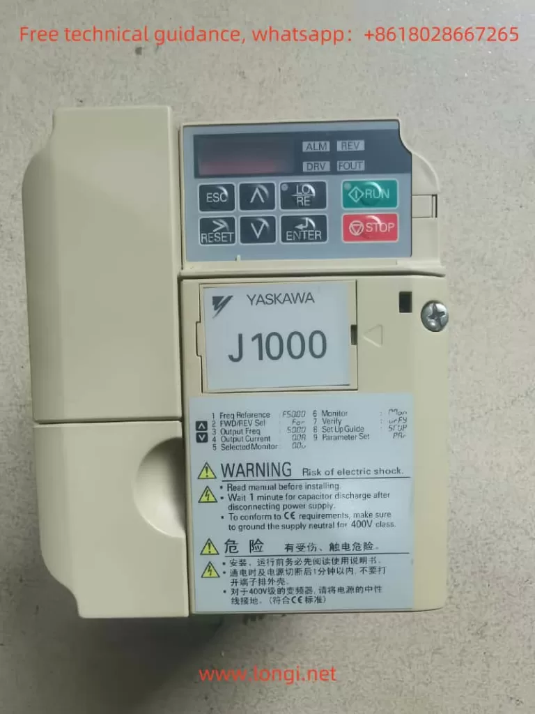
The Yaskawa J1000 series inverters are widely used in industrial automation for their stable control performance and high energy efficiency. However, during actual operation, inverters may encounter various faults, one of which is the “Uu1” fault. This article will analyze the meaning, causes, and solutions for the Uu1 fault from both external and internal perspectives, providing a reference for inverter maintenance and repair.
I. Meaning and Causes of the Uu1 Fault
1. Fault Meaning
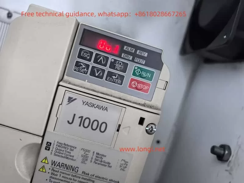
The Uu1 fault indicates an undervoltage output fault, meaning the inverter detects that the output voltage is below the set minimum value, triggering a protective mechanism. This fault often causes the inverter to stop, protecting the motor and load from potential damage.
2. Causes of the Fault
The Uu1 fault can be attributed to several factors:
- Unstable power supply: The input voltage to the inverter is lower than the rated range, leading to insufficient output voltage.
- Wiring issues: Poor contact in the input or output wiring causes voltage drops.
- Internal inverter faults: Damage to the inverter’s internal circuits or components results in abnormal output voltage.
- Motor or load faults: Issues with the motor or load cause abnormal feedback voltage.
3. On-Site Handling Methods
To address the Uu1 fault on-site, follow these steps:
- Check the power supply voltage: Use a voltmeter to measure the inverter’s input voltage and ensure it is within the rated range. If the voltage is too low or unstable, inspect the power supply, and replace it or use a voltage stabilizer if necessary.
- Inspect the wiring: Check the input and output wiring for proper contact, ensuring no loose or disconnected wires. If poor contact is found, reconnect the wiring and tighten the screws.
- Examine the inverter internally: If the power supply and wiring are fine, the issue may lie within the inverter. Consult a professional technician or the manufacturer for repairs.
- Check the motor and load: Ensure the motor is operating normally and inspect the load for any issues.
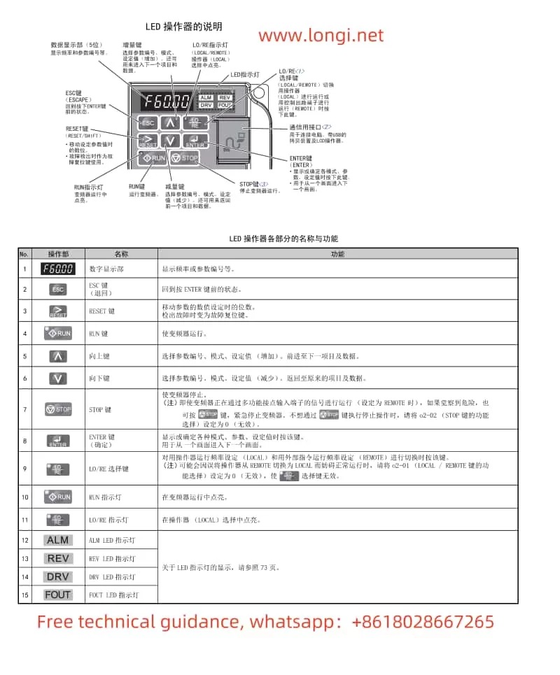
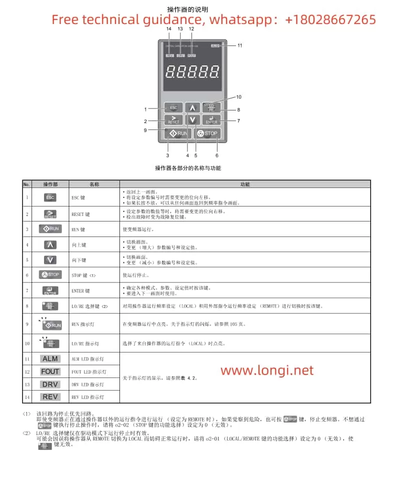
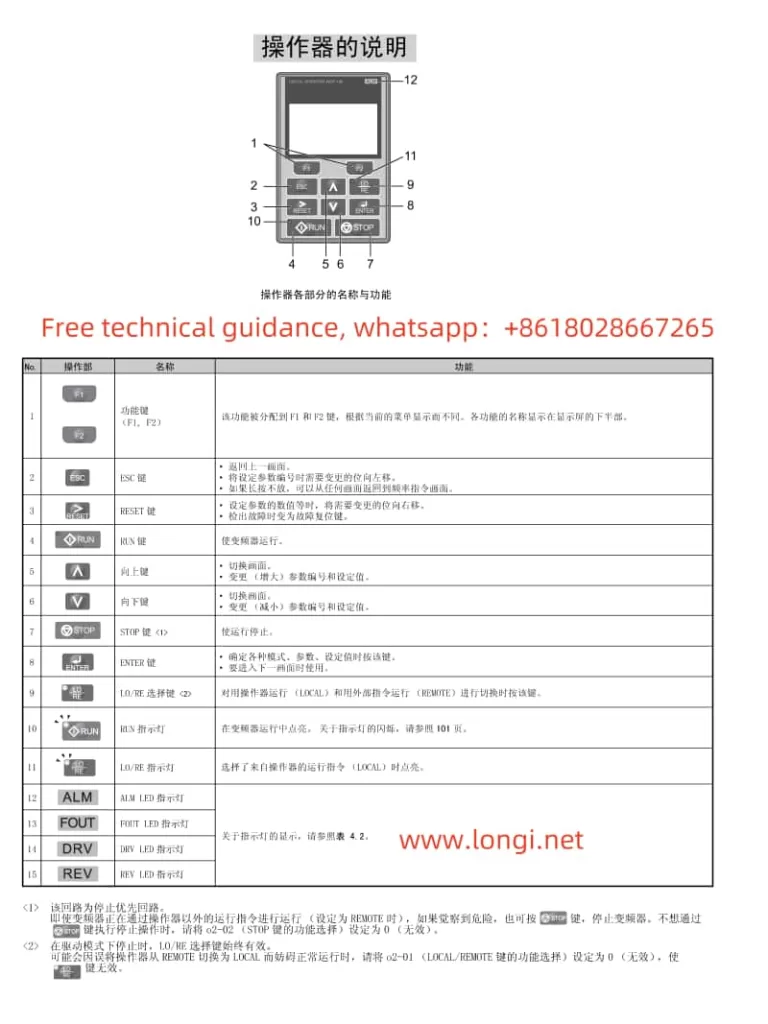
- Reset the fault: After resolving the issue, press the RESET button on the inverter to clear the fault. Restart the inverter and observe its operation.
II. Analysis of Electrical Issues from the Inverter’s Internal Structure
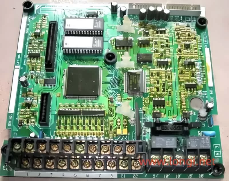
1. Overview of the Inverter’s Internal Structure
The internal structure of the Yaskawa J1000 series inverter primarily includes the rectifier circuit, inverter circuit, control circuit, and protection circuit. The rectifier circuit converts AC voltage to DC voltage, the inverter circuit converts DC voltage to variable-frequency AC voltage, the control circuit regulates the output frequency and voltage, and the protection circuit detects and protects against faults such as overload, overvoltage, and overcurrent.
2. Electrical Issues Related to the Uu1 Fault
The Uu1 fault is typically associated with the inverter’s output circuit and involves the following aspects:
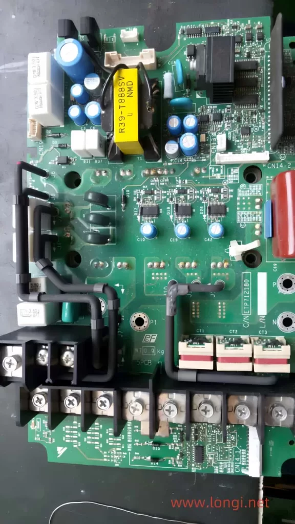
- Rectifier circuit faults: Damage to diodes or capacitors in the rectifier circuit can lead to insufficient DC voltage, affecting the output voltage.
- Inverter circuit faults: Damage to IGBT modules or driver circuits in the inverter circuit can cause abnormal output voltage.
- Control circuit faults: Faults in the microprocessor or driver chips in the control circuit can result in inaccurate output voltage regulation.
- Protection circuit faults: Malfunctioning detection components or protection chips in the protection circuit can lead to incorrect identification of undervoltage.
3. Electrical Repair Methods
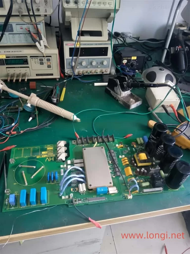
To repair the Uu1 fault, follow these steps:
- Inspect the rectifier circuit: Use a multimeter to test the diodes and capacitors in the rectifier circuit to ensure they are functioning correctly. Replace any damaged components.
- Check the inverter circuit: Inspect the IGBT modules and driver circuits for proper operation. Replace any faulty modules or chips.
- Examine the control circuit: Test the microprocessor and driver chips to ensure they are functioning correctly. Replace any faulty chips.
- Inspect the protection circuit: Check the detection components and protection chips in the protection circuit for proper operation. Replace any faulty components.
III. Comprehensive Solutions for the Uu1 Fault
1. Preventive Measures
To prevent the occurrence of the Uu1 fault, consider the following measures:
- Regularly check the power supply voltage: Periodically inspect the inverter’s input voltage to ensure stability.
- Maintain wiring connections: Regularly check the wiring for proper contact and address any issues promptly.
- Inspect the inverter internally: Periodically check the inverter’s internal circuits to identify and resolve potential faults early.
- Maintain the motor and load: Regularly inspect the motor and load to ensure they are operating correctly.
2. Fault Handling Procedure
When addressing the Uu1 fault, follow this procedure:
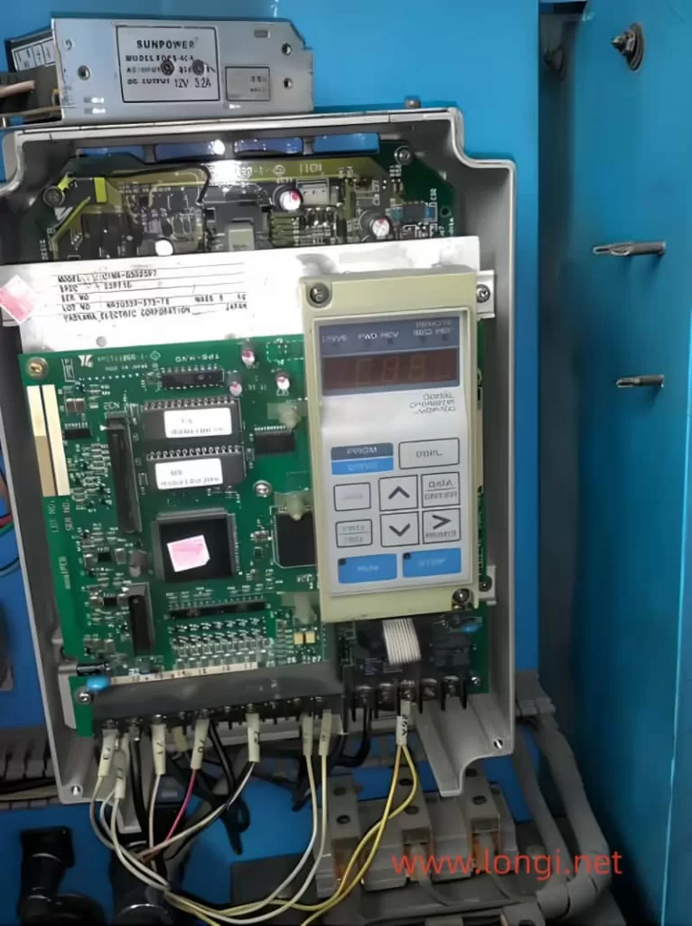
- Confirm the fault: Verify the Uu1 fault on the inverter’s display.
- Check the power supply voltage: Ensure the input voltage is normal.
- Inspect the wiring: Check for proper wiring connections.
- Examine the inverter internally: Ensure the internal circuits are functioning correctly.
- Check the motor and load: Verify that the motor and load are operating normally.
- Reset the fault: After resolving the issue, reset the inverter and observe its operation.
3. Professional Support
If the Uu1 fault cannot be resolved through the above methods, consult a professional technician or the manufacturer for further assistance.
Conclusion
The Uu1 fault in the Yaskawa J1000 series inverters is a common undervoltage output fault with complex causes, involving the power supply, wiring, internal circuits, motor, and load. Through systematic fault analysis and step-by-step troubleshooting, the Uu1 fault can be effectively resolved, ensuring stable inverter operation. Regular maintenance and preventive measures are also crucial in avoiding such faults.