Posted on Leave a comment

Why should we add an input reactor to the fragile small power VFDs

A factory has a 5.5 kW submersible pump. To facilitate water volume adjustment and energy-saving operation, an electrician proposed using a VFD to drive the pump.

The task was taken on by Mr. Zhang, a friend of the electrician. For safety, Mr. Zhang selected a 7.5 kW VFD from a reputable brand. This brand’s VFDs are widely used in various industries such as plastics, chemicals, and wood processing without significant issues, indicating decent quality. The VFD control box was installed in the boiler room, with power sourced from the workshop distribution panel. The three-phase voltage balance was excellent, maintaining within 380V ±5%. During the trial run, the VFD did not need to operate at full speed, running around 30Hz with the working current at half of the VFD’s rated current. Mr. Zhang was confident that the VFD would operate safely for a long time.

However, three days later, the factory’s electrician called Mr. Zhang, reporting that the VFD had stopped, and the control panel was unresponsive, indicating no power. Surprised, Mr. Zhang visited the site and confirmed the issue. Assuming a quality problem with the VFD, he replaced it with another 7.5 kW VFD from the supplier and sent the defective one for repair.

This time, the VFD failed after just a day and a half. Frustrated, Mr. Zhang called the supplier to complain and replaced the VFD with another brand. He again checked the operating voltage and current, which were similar to the initial installation, indicating no issues with the pump or power supply. Mr. Zhang concluded that the first batch of VFDs might have had quality defects and hoped the new brand would solve the problem.

Unexpectedly, the newly installed VFD also failed within hours, with the factory’s electrician calling Mr. Zhang again. The recurring issue led to reprimands from the factory boss to the electrician, who then passed the blame to Mr. Zhang. Baffled, Mr. Zhang inspected the three faulty VFDs. He found that two had open circuits between the R and P1 (external brake resistor terminal), possibly due to damaged charging resistors, which indicated rectifier circuit issues. The third VFD had a short circuit between R and S, suggesting a failed rectifier module. However, the inverter modules in all three VFDs were intact. The damages seemed to result from power surges, not load-related issues, as the three-phase supply voltage and input current were normal. Having worked with VFDs for several years, Mr. Zhang found this problem unprecedented.

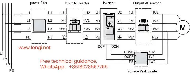
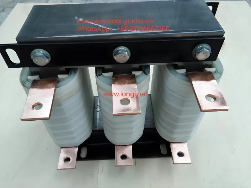
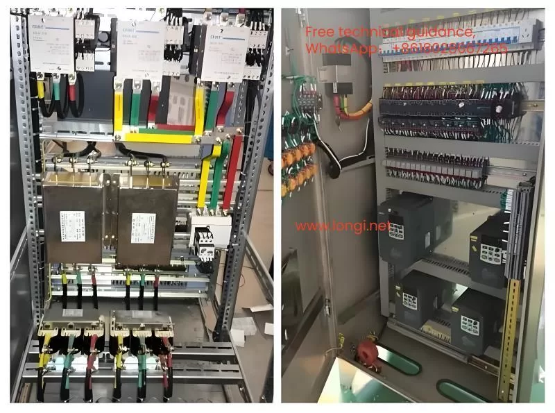
In desperation, Mr. Zhang called his friend, electrician Mr. Li, for advice. Mr. Li suggested installing a three-phase input reactor before the VFD’s power terminals to solve the problem.

Mr. Zhang inquired about the cause of the failures. Mr. Li explained three potential reasons related to the power supply:

1. The submersible pump continued to operate after work hours for employee showers, meaning a 630 kVA transformer supplied a 7.5 kW VFD, causing a significant capacity disparity. The VFD’s input current contained high harmonic components, generating large rectifier inrush currents that damaged the rectifier module and charging resistor during startup.

2. The workshop distribution panel might have parallel capacitor compensation cabinets. The start and stop of large motors (above 100 kW) and the switching currents of capacitors created harmful voltage spikes and inrush currents, impacting the VFD.

3. The same power line might have other large VFDs, soft starters, or DC speed controllers. The nonlinear rectifier currents from these devices severely distorted the power supply waveform, increasing harmful harmonics and deteriorating power quality.

Mr. Li noted that input reactors, often depicted in VFD wiring diagrams, are frequently omitted during installation to save costs, leading to such issues.

Mr. Zhang didn’t have ready-made three-phase reactors and needed an immediate solution. Mr. Li suggested using XD1 series chokes from old capacitor compensation cabinets as reactors, which could suppress inrush currents effectively. Mr. Zhang contacted several suppliers but learned that most manufacturers had stopped producing these chokes.

Under pressure, Mr. Zhang reached out to Mr. Li again, demanding a solution. Mr. Li, while having lunch, suggested using current transformers (CTs), which Mr. Zhang likely had. Any CT, regardless of size, with a rated current of 5A, could be used. CTs with more winding turns (e.g., 50/5) would offer better inrush current suppression and filtering but might have a higher voltage drop. Conversely, CTs with fewer turns (e.g., 250/5) would have a smaller voltage drop but less effective smoothing. Depending on the VFD’s rated current, Mr. Li recommended using three CTs per phase or two if the running current was around 7A. CTs would provide better inductance and performance than XD1 chokes.

After installing CT-based “input reactors,” the VFD’s input current became stable, reducing harmonics and voltage spikes, ensuring safer operation.

Months later, Mr. Zhang checked with the factory electrician, who confirmed that the VFD had been operating normally. Mr. Zhang realized the VFD failures were due to power supply issues, not the VFD quality. He felt vindicated and teased the electrician about owing him a drink for resolving the issue.

Posted on Leave a comment

The repair process of an unlicensed VFD caught up with lightning speed

In movies and TV shows, when a Taoist from Maoshan encounters an urgent and difficult situation, he often recites a curse: “The Supreme Old Lord is as sick as a law… If something difficult happens, it should be solved by the curse.”. If there is an urgent VFD repair, we can also recite a few mantras and find the “smart” method for quick maintenance.
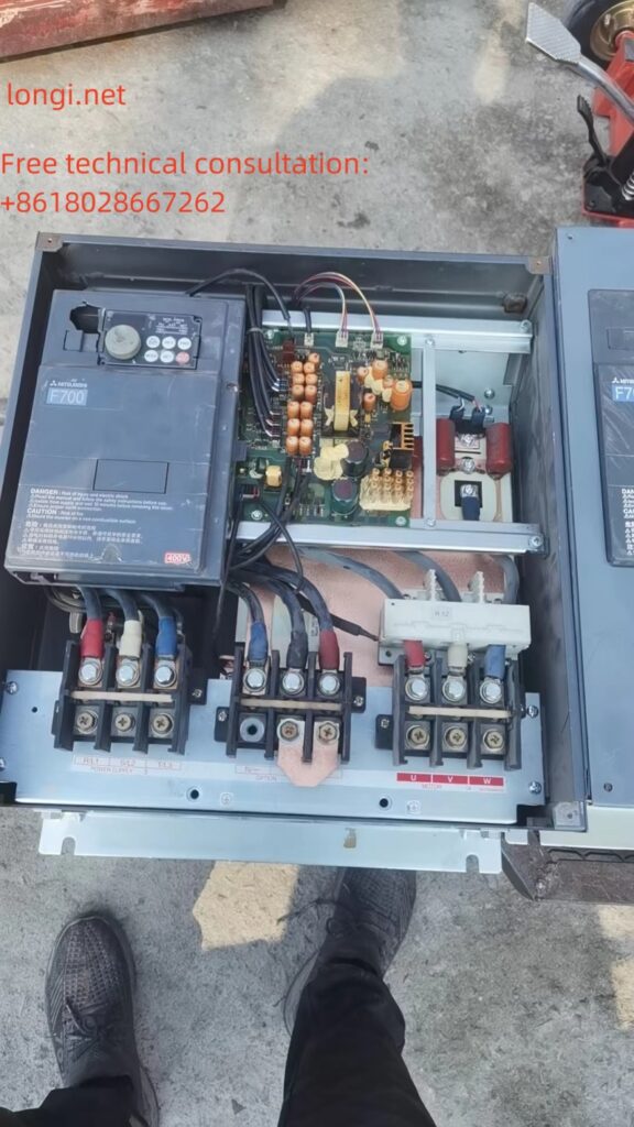
On a rainy day, thunder and lightning flash. The door of the maintenance department was suddenly forcefully pulled open by someone. Three or four strong men, carrying an unmarked 75kW VFD, strode in and asked, “Our workshop is for refining silver, and the frequency converter was damaged by lightning.”. Urgent use! Can the malfunction be detected and repaired within three hours. Okay, don’t bargain; If you don’t have diamond, don’t take on porcelain work. Let’s quickly change the door. It’s not just you who can fix VFD.
This VFD may be able to earn half a month’s salary. No second words, fight!

I roughly inquired about the damage to VFD. During operation, due to lightning strikes introduced from the three-phase power supply, even the main power switch in the workshop tripped. Close the power switch of VFD again, there is a popping sound, and the switch jumps open again.
In this situation, there must be a short circuit fault in the three-phase rectifier circuit of VFD. Instead of being busy with power on, use the resistance range of the multimeter’s R, S, T power input terminals and U, V, W output terminals to determine the resistance of the main circuit with the P and N terminals of the DC circuit. There is a short circuit phenomenon in the measurement, rectification, and inverter power circuits. Detailed inspection after disassembly revealed that two rectifier modules were damaged, one inverter module was broken, and the energy storage capacitor was tested and found to be fine.
The repairman asked, “Isn’t it enough to replace these three faulty parts?”? Answer: Don’t be impatient. Due to the introduction of lightning strikes within VFD, the situation is complex and the quality of the control circuit board is unclear. If the inverter power module is damaged, it will have an impact on the driving circuit. If there is a hidden fault, the replacement module will be damaged again. Further investigation is needed to determine whether to replace the module.
Key contents to be checked: 1. Whether the CPU motherboard is damaged, especially whether the CPU chip is damaged; 2. Inverter pulse transmission circuit, including driving circuit and inverter pulse front-end circuit. Especially for the driving circuit, the triggering terminal circuit of the IGBT should be checked for any open circuit or negative pressure power supply; 3. Other circuits, whether the control terminal circuit has been damaged by lightning strikes, and whether the control circuit (fault detection circuit, etc.) has been damaged.
The key among them is that as long as the CPU can output six inverter pulses, repairing other faults should be easy.

(A) Power on the switch power supply or troubleshoot the switch power supply:
Remove the CPU motherboard and power/driver board from the inverter casing and place them on the maintenance workbench. Power should be supplied to the switch power supply of the circuit board first, or the switch power supply should be repaired first to facilitate troubleshooting of other circuits. I tested the power supply terminals of the switching power supply and the filtering capacitor at both ends of the secondary rectification circuit of the switching transformer, and there was no short circuit phenomenon. It is possible to power on the switching power supply. The power supply source of the Shunxia switch power supply is directly taken from the 530V DC circuit of the DC circuit. If measured on the circuit, the drain (collector) of the switching transistor of the switching power supply should be connected to the P-terminal of the DC circuit, and the source (emitter) should be connected to the N-terminal of the DC circuit.
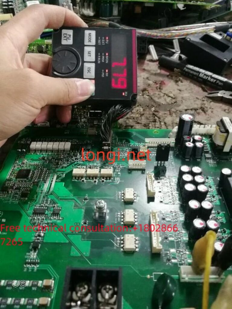
Alright, connect the 500V DC maintenance power supply to the power supply terminal of the switch mode power supply (pay attention to polarity, it can be bad if connected in the opposite direction), it’s not bad! The corresponding changes in characters during the startup period on the operation display panel indicate that the switch power supply and the peripheral circuit of the CPU chip are basically working normally, and the CPU is also good.
(B) Release the OH (module overheating) fault alarm:
After the startup character on the operation display panel flashes, an OH (module overheat) fault code is reported. Press the RST reset button on the operation display panel, OH disappears once, and it is displayed again, unable to reset. At this time, the frequency converter is in a fault locked state and refuses to accept operating signals, making it impossible to detect whether the inverter pulse transmission circuit is normal. The OH alarm must be disarmed. Observing the main circuit, two normally closed contact type thermal relays are installed near the heat sink module. When the circuit board is disconnected from the main circuit, it is equivalent to the temperature sensor’s normally closed point breaking, reporting an overheat signal. Find the corresponding temperature sensor terminals on the circuit board, short circuit them with wires or solder, and there should be no OH fault reported. Some frequency converters use thermistors to detect the temperature of the module. When the terminal is open, an OH fault will also be reported. Simply remove the temperature sensor and insert it into the corresponding terminal on the control board. Still report OH, don’t worry, there may be related temperature detection signals sent to the control board.
Observe the socket and lead of the cooling fan, which is a three wire fan. Two wires are the positive and negative terminals of the 24V power supply, and one wire is the signal wire. Return the operation/fault signal to the control board. If you remove the fan and plug it back into the control board, it would be too troublesome. There is a simple way to find the positive and negative wires, and test connecting the third wire to the positive and negative power supply terminals respectively. When this wire is connected to the positive power supply terminal, the OH fault code on the operation display panel disappears.
(C) Release Uu (undervoltage) and input phase loss alarm:
After a brief moment of joy, the operation display panel showed another Uu (undervoltage) fault, and the frequency converter was still in a fault locked state.
When the switching power supply adopts 265V (or 300V) DC power supply, we disconnect the control board from the main circuit and separately supply 265V (or 300V) DC power to the switching power supply. Most of the operation panels will report Uu faults (some frequency converters, DC circuit voltage detection signals are obtained in the secondary rectification circuit of the switching transformer, so Uu faults will not be reported), because the input of the DC circuit detection circuit is in an open circuit state, and the circuit output is an undervoltage signal. From the DC circuit voltage introduction terminals (P, N terminals), find the input resistance network of the DC circuit detection circuit, a large high resistance circuit, seven or eight phases in series, because the switching power supply is 300V DC power supply at this time, directly introduce it into the DC circuit voltage detection circuit, or report a Uu fault. Short circuit a few resistors in the input resistor network (if there are 8 resistors, 3 can be short circuited for testing) to adapt to the 300V voltage output range.
Introduce a DC voltage artificially into the DC detection circuit and modify the detection to meet the requirements of the voltage input range. Some frequency converters may not report Uu faults, but they may also report “charging contactor not engaged fault”, while others may still report Uu faults. Don’t worry, there may be related voltage detection signals sent to the control board.
The charging contactor cannot be removed and connected to the control board in the main circuit. The frequency converter often has a status detection circuit for the auxiliary contact of the charging contactor. Due to the disconnection between the control board and the main circuit, the CPU detects that the auxiliary contact of the charging contactor is always in an open circuit state after the control board is powered on, and will also report Uu or “charging contactor not engaged fault”. Find the lead terminals of the auxiliary contacts of the charging contactor from the main circuit, determine the corresponding socket terminals of the control board, short circuit or solder the lead terminals with wires, and tell the CPU that the charging contactor has been closed.
After short circuiting the lead terminals of the auxiliary contacts of the charging contactor, the operation display panel finally stopped tripping Uu fault.
(D) Release OC (module overcurrent or output short circuit) fault alarm:
After a brief moment of joy, the fault code no longer jumps. From the display on the operation display panel, it appears that the inverter has entered standby mode and can be started for maintenance of the inverter pulse transmission channel. Press the start/stop button on the operation display board, but the frequency converter does not respond. The user may have set it to terminal operation. Ask the repairman, and indeed. For the convenience of operation, if the control parameters can be modified (if there is a frequency converter manual at hand), or the operation can be changed to start/stop and frequency adjustment using the control panel; If it is inconvenient to modify the parameters, you can try inputting the operation and frequency signals from the control terminal. Measure the frequency and adjust the power supply to 10V for normal output. Short circuit it to the input end of the 0-10V frequency signal to input the highest operating frequency command for the frequency converter (it is not troublesome, but can also be adjusted with an external potentiometer). Short circuit the forward running terminal to the digital common terminal for a startup test, and the operation display panel will display an OC fault code. Of course, the frequency converter is still in a fault locked state and cannot accept the operation.
The power module cannot function without various comprehensive protections, but at this point, I really feel that these fault alarms are troublesome. However, if they are not resolved, the inverter pulse transmission circuit cannot be repaired. Slowly, when an alarm signal is issued, it will be tracked and released. Generally, when the control circuit board is disconnected from the main circuit, three or four faults will jump out. Pay attention to finding the source of each signal from each plug-in terminal, or from the input and output sides of the plug-in terminal or the optocoupler that transmits the signal, use wire short circuiting method to force the CPU to input a “normal” signal and release the fault lock state.
The OC signal is mostly sent back to the CPU by the IGBT voltage drop detection circuit (IGBT protection circuit) of the driving circuit. When there is a fault in the output current detection circuit, an OC fault will also be reported, but this situation is relatively rare. Following the principle of easy first and difficult later, the OC signal returned by the driving circuit can be released first, and then the output current detection circuit can be detected.
The commonly used ICs for driving circuits are PC923, PC929, and A316J. The former uses the OC signal output by the internal IGBT protection circuit of PC929, which is then sent to the CPU through an external optocoupler. Find the optocoupler connected in parallel with PC929, and short-circuit its input side with a soldering iron to release the OC alarm (it is a fast method, not a good method); The latter, the 5 pins of the driver chip A316J are the OC signal output pins, which are separated from the copper foil strip to isolate the transmission of OC signals; But this method is not very convenient. Although it blocks the transmission of OC signals, it is advisable to check whether the CPU and the front-end inverter pulse transmission circuit have output inverter pulse signals. However, the drive IC itself is still in a fault locked state, which is not conducive to repairing the drive circuit.
A good solution is to manually input an IGBT “normally open” signal to the IBGT detection circuit, so that the driving IC itself no longer reports OC faults during the input inverter pulse period. The general driving circuit is implemented by the lower three arm driving circuit to detect the voltage drop of the IGBT transistor. The trigger terminal is used to short circuit the output end of the inverter pulse to the OV end of the driving power supply (the connection point with the N end of the main circuit), which is also relatively easy to find.
(E) Perform maintenance on the drive circuit:
Finally, the frequency converter can accept the startup signal. Looking at the gradually increasing output frequency indicator displayed on the control panel, I breathed a sigh of relief, indicating that the CPU circuit and control terminal circuit are both good. The repair of the frequency converter is basically without any suspense.
Measure the six inverter pulse input terminals of the driving IC, and there is a significant voltage change in the start and stop states. The six inverter pulses from the CPU motherboard have been input into the driving circuit intact and undamaged. The CPU motherboard is good! Measure the output status of six inverter pulses from the pulse output terminals of the power/driver board, and check if the negative cutoff voltage is normal and if there are normal pulse outputs. Does the voltage amplitude and current amplitude of the pulse output meet the normal requirements? Due to the damage of the IGBT causing impact on the driving IC, there are two driving circuits that cannot output pulse signals normally. This is simple. A power amplifier consisting of a driver IC and a rear stage consisting of two transistors was found to have damaged components. After replacement, all six inverter pulses were output normally.
The maintenance process has been declared completed. The entire maintenance process took exactly 45 minutes. After the maintenance is completed, it seems like we won a small battle so happily. The next task is to replace and purchase modules.

Throughout the entire maintenance process, four strong men were eagerly staring at the frequency converter, including one electrician who was extremely excited: he had learned and really had real skills. I didn’t expect it to be so troublesome. Blowing up a module is not as simple as replacing it.
To the repairman, the control circuit has been repaired, but there is no power module at hand. Then, you can go to the same city to “search” for it. If not, it will only be sent from outside the city. You will have to find your own way to delay your silver refining.
The four repairmen all laughed and said, “No problem, no problem. Please hurry up and send the package.”.
The various methods used during the maintenance process are scattered in my other blog posts, but they belong to local maintenance methods. For actual maintenance, sometimes there is a small gap between what is explained by a single unit circuit, which is difficult to understand. Through the description of a specific maintenance example process in this article, the application of various maintenance methods can be integrated and integrated.

Posted on Leave a comment

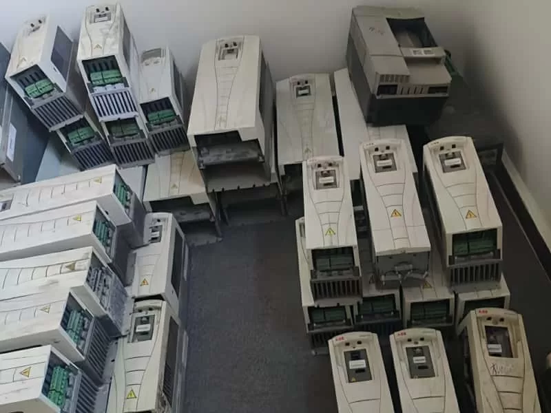
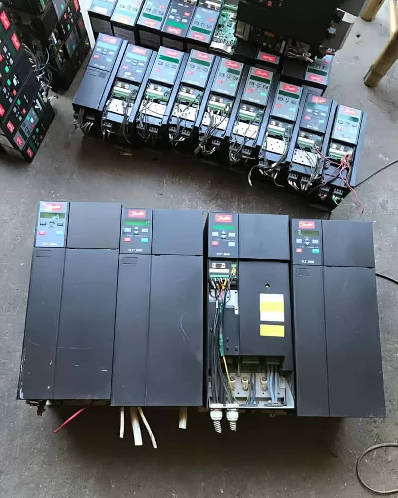
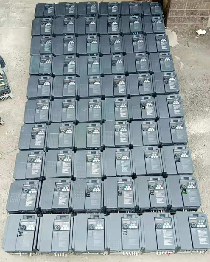
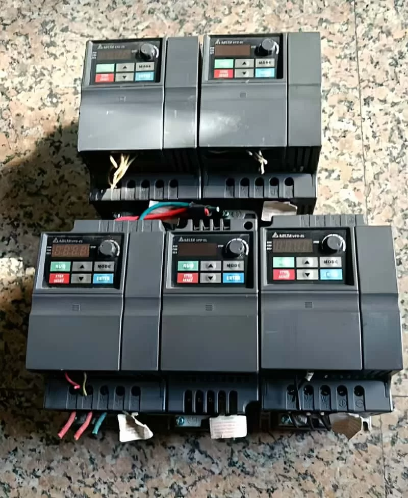
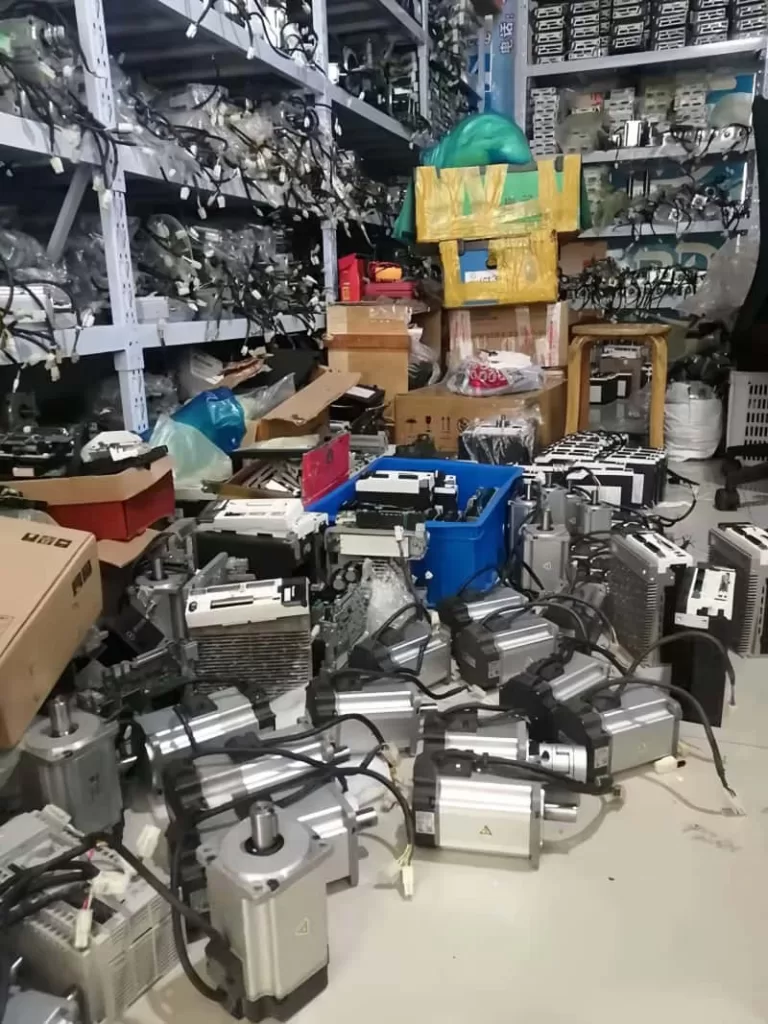
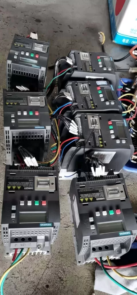
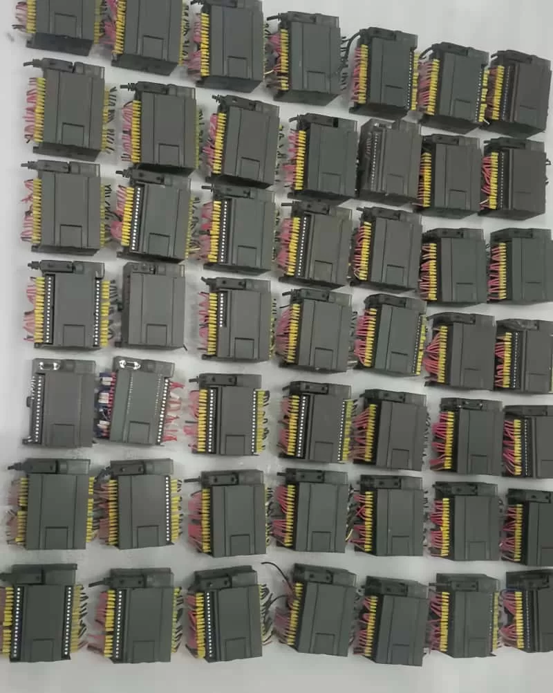
Looking to Sell Used Industrial Control Products? Get High-Price Cash Recovery with Longi Electromechanical!

Do you have surplus or second-hand industrial control products lying around, such as VFDs, PLCs, touch screens, servo systems, CNC systems, robots, instruments, sensors, or control panels? Longi Electromechanical is here to help you monetize your inventory quickly and efficiently, regardless of its condition or age.

With over 20 years of experience in the industry, Longi Electromechanical has built a reputation for integrity, fair dealing, and conscientious management. We take every transaction seriously and strive to offer the best possible prices to our partners.

Our procurement process is designed to be fast, convenient, and secure. We follow strict principles of confidentiality and security, ensuring that your transactions are handled with the utmost care. We offer cash payments and can even estimate a reasonable acquisition price online through pictures or videos provided by you.

Whether you prefer logistics collection, online payment, or face-to-face transactions, we’re here to accommodate your needs. So why wait? Contact Longi Electromechanical today and start accelerating your capital recovery with our high-price cash recovery services for used industrial control products!

Longi Electromechanical: Your Trusted Partner for Industrial Control Product Recycling.

Posted on Leave a comment

Global Ultrasonic Equipment Maintenance Center – Longi Electromechanical Company

Professional Ultrasonic Equipment Repair Services

Longi Electromechanical Company specializes in the repair of various types of ultrasonic equipment using advanced AI methods and a dedicated technical team. We offer component-level maintenance and can resolve common issues on the same day, minimizing downtime and maximizing customer productivity. With a vast experience of repairing over 2000 ultrasonic devices, we have honed our skills to handle a wide range of brands and models.

Produktion mit CNC-Maschine, Bohren und Schweißen und Konstruktionszeichnung im Industriebetrieb.

Contact Us:
Phone/WhatsApp: +8618028667265

Key Services and Features:

  • Comprehensive Repair Solutions: From plastic hot plate welding machines to ultrasonic flaw detectors, we repair a diverse range of ultrasonic equipment.
  • Brand Expertise: We have experience with numerous brands, including Minghe, Changrong, Swiss RINCO, and many more, ensuring optimal performance restoration.
  • Warranty and Cost-Effectiveness: Repaired equipment comes with a one-year warranty for the same problem point, and our maintenance costs are competitive.
  • Quick Turnaround: We prioritize efficient repairs to get your equipment back in operation as soon as possible.

Types of Ultrasonic Equipment We Repair:

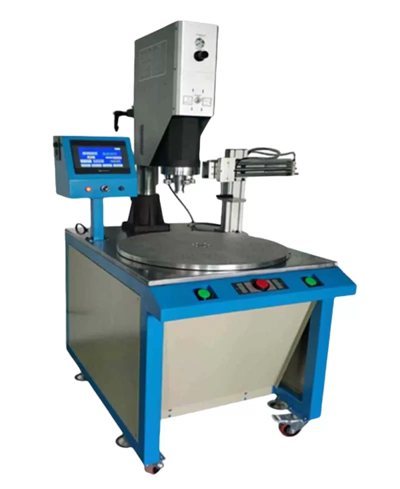
  • Plastic Welding Equipment: Ultrasonic welding machines, hot plate welding machines, multi-head ultrasonic welding machines, and more.
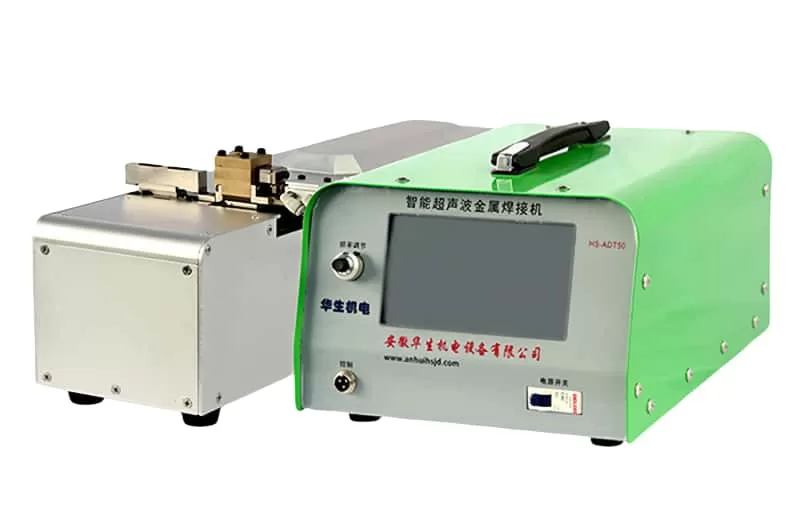
  • Metal Welding Equipment: Ultrasonic metal welding machines, spot welding machines, wire welding machines, and roll welding machines.
  • Automotive Welding Equipment: Door panel welding machines, interior part welding machines, instrument panel welding machines, and more.
  • Specialized Equipment: Ultrasonic flaw detectors, cutting machines, food cutting machines, tool heads, and various other ultrasonic devices.
  • Components and Parts: Ultrasonic vibrating plates, power boards, transducers, generators, and supporting tooling.

Common Faults We Address:

  • Cleaning water surface not vibrating
  • Debonding between vibrator and load
  • Mold head misalignment
  • No display on startup
  • Overload or overcurrent during welding
  • High current during testing
  • Insufficient or excessive welding heat
  • Vibrator leakage waves
  • Unresponsive buttons
  • Travel protection issues
  • Power adjustment problems
  • Insufficient ultrasonic intensity
  • Cracked transducer ceramic
  • Burned-out power tube
  • Voltage stabilization issues
  • Inductor and isolation transformer problems
  • Disconnected vibrator wire

Repair Principles:

  1. Observe, Understand, Act: Begin by inquiring about the issue from frontline staff, checking for voltage fluctuations, and understanding the context before taking action.
  2. Simple Before Complex: Rule out peripheral issues like the environment, electricity, load, raw materials, and molds before diving into more complex repairs.
  3. Address Mechanical Issues First: Visible mechanical problems, such as mold issues, should be addressed before exploring electrical causes.

Trust Longi Electromechanical Company for reliable, efficient, and cost-effective ultrasonic equipment repair services. Contact us today to learn more about our services and how we can help keep your ultrasonic equipment running smoothly.

    Posted on Leave a comment

    Global Instrument Maintenance Center

    Intelligent Precision Instrument Maintenance Base,Professional maintenance of various intelligent instruments and meters, phone/WhatsApp:+8618028667265, Mr. Guo

    Longi Electromechanical specializes in repairing various imported intelligent precision instruments and meters, and has accumulated rich maintenance experience over the years, especially environmental testing instruments, electrical instruments, thermal instruments, acoustic and flow instruments, and electrical instruments. Environmental testing instruments, thermal instruments, acoustic and flow instruments,
    We can quickly repair radio instruments, length instruments, environmental testing equipment, quality inspection instruments, etc.
    Different instruments have different characteristics and functions, and their circuits and structures are also different. Even for the same instrument, if there are different faults, repairing them is still a different solution. Rongji Company has numerous high-end maintenance engineers equipped with artificial intelligence AI detection instruments, which can provide you with multi-dimensional solutions to various tricky instrument problems.

    Over the years, Longi Electromechanical has repaired instruments including but not limited to:

    Spectrum analyzers, network analyzers, integrated test instruments, 3D laser scanners, noise figure testers, receivers, telephone testers, high and low-frequency signal sources, audio and video signal analyzers, constant temperature and humidity chambers, thermal shock chambers, simulated transport vibration tables, mechanical vibration tables, AC grounding impedance safety testers, safety comprehensive analyzers, withstand voltage testers, battery internal resistance testers, high-precision multimeters, precision analyzers, gas and liquid analyzers, metal detectors, LCR digital bridges, oscilloscopes, electronic loads, power meters, power analyzers, multimeters, DC power supplies, AC power supplies, CNC power supplies, variable frequency power supplies, and various communication power supplies.

    We have repaired the following brands:

    Chroma, ITECH, Tonghui, Agilent, Tektronix, Keysight, Fluke, Keithley, Rohde & Schwarz, Lecroy, Anritsu, Rigol, and many more.

    Longi Electromechanical strives to provide comprehensive repair services for a wide range of instruments and equipment, ensuring that our customers’ devices are restored to optimal performance.

    Longi maintenance engineers possess over twenty years of experience in instrument repair. We have multiple engineers who excel in repairing imported precision instruments. The team works together, enabling faster troubleshooting and quick resolution of complex issues while improving the repair rate of instruments.

    Spare parts are fundamental to successful repairs. Many imported instruments and meters require specialized components that cannot be easily replaced with generic market parts. Rongji Electromechanical maintains a long-term stock of electronic components for various instruments, ensuring their availability when needed.

    Documentation and manuals are also crucial tools for ensuring rapid repairs. Accessing these resources allows for quick research and analysis of faults, enabling engineers to quickly identify the repair priorities. Longi Electromechanical has a long history of collecting specifications for various brands and models of instruments, greatly aiding in the repair process.

    The intelligent instruments that have been carefully repaired by us can generally continue to be used for about 5 years. We promise that when the same malfunction occurs again, our repair service will provide a one-year warranty service.

    Posted on Leave a comment

    Global Touch Screen Repair Services: Expert Maintenance for All Your Touch Screen Needs

    Global Touch Screen Repair Services: Expert Maintenance for All Your Touch Screen Needs

    Touch screens have become an integral part of our daily lives, revolutionizing the way we interact with machines in various industries including industrial, commercial, and medical fields. These versatile devices come in different forms such as resistive, capacitive, infrared, and ultrasonic screens, each serving unique purposes. However, due to their frequent use and delicate glass structure, touch screens are prone to damage, particularly to the outer touch surface known as the “touchpad.”

    For over two decades, Rongji Electromechanical Maintenance has been a trusted name in the touch screen repair industry. With extensive experience in handling touch screens across diverse sectors, we specialize in repairing both resistive and capacitive screens used in automobiles and other critical applications. Our expertise ensures that your touch screens are restored to optimal functionality, minimizing downtime and maximizing efficiency.

    The Repair Process: A Step-by-Step Guide

    Disassembly and Inspection:
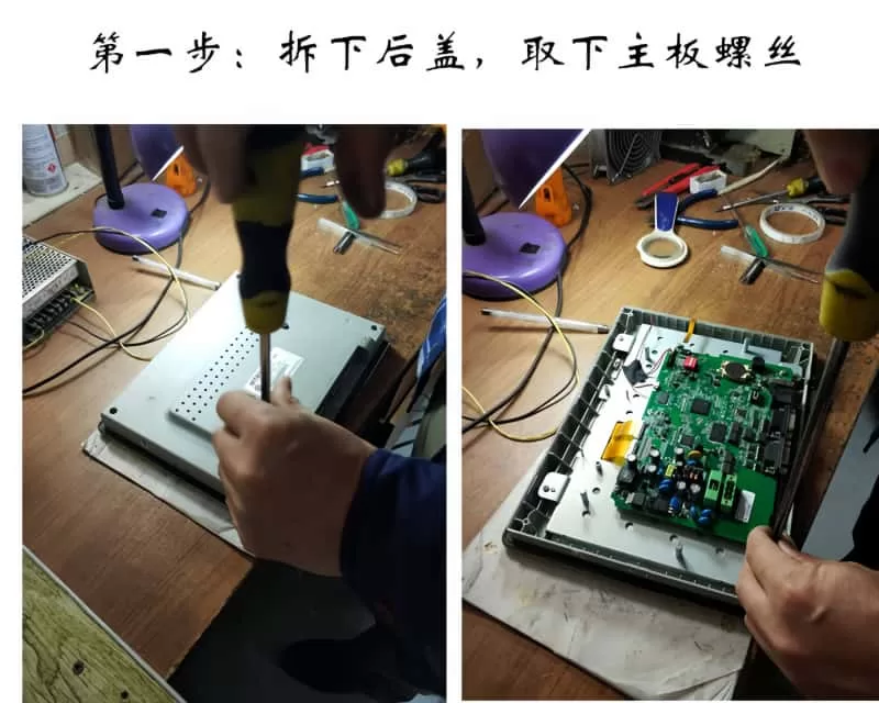
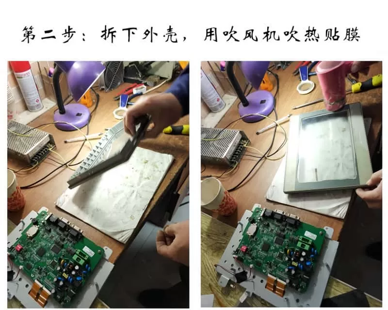
    We begin by carefully removing the back cover and motherboard screws of the touch screen. This step allows us to access the internal components and assess the extent of the damage.

    Heating and Peeling:
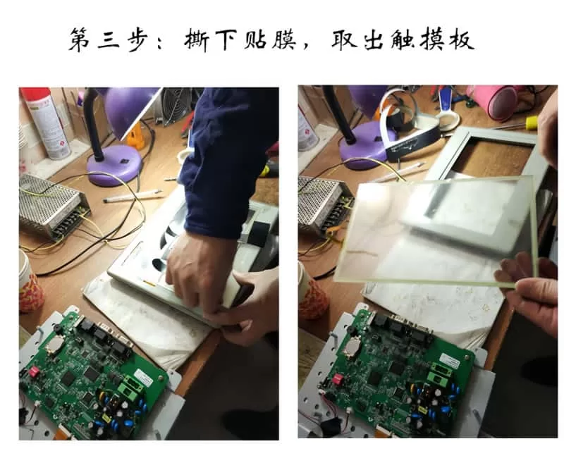
    Our skilled technicians use a hair dryer to gently heat the film adhering to the touch screen. This softens the adhesive, making it easier to peel off the outer layer without causing further damage.

    Touchpad Replacement:
    Once the old touchpad is removed, we replace it with a high-quality touchpad from our inventory. Longi Electromechanical Company has reverse-engineered various touch screen models, ensuring that our replacement parts are fully compatible with the original equipment.

    Reassembly:
    We apply double-sided tape to the touch screen border and securely attach the new touchpad. This ensures a perfect fit and optimal performance.

    Testing and Fine-Tuning:
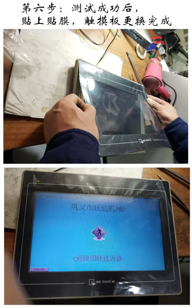
    With the new touchpad in place, we reinstall the motherboard and LCD, then flip the unit over to test its functionality. Our rigorous testing process ensures that the touch screen operates smoothly and accurately.

    Final Assembly and Quality Check:
    After successful testing, we apply a protective film to the touch screen and reassemble the unit. A final quality check is performed to ensure that the repair meets our high standards.

    Addressing Complex Issues

    In addition to touchpad replacements, we also handle more complex issues such as circuit failures and software problems. Our team uses professional software analysis and hardware processing techniques to diagnose and repair these issues, ensuring that your touch screen is fully restored to its original state.

    Our Repair Services Cover a Wide Range of Brands

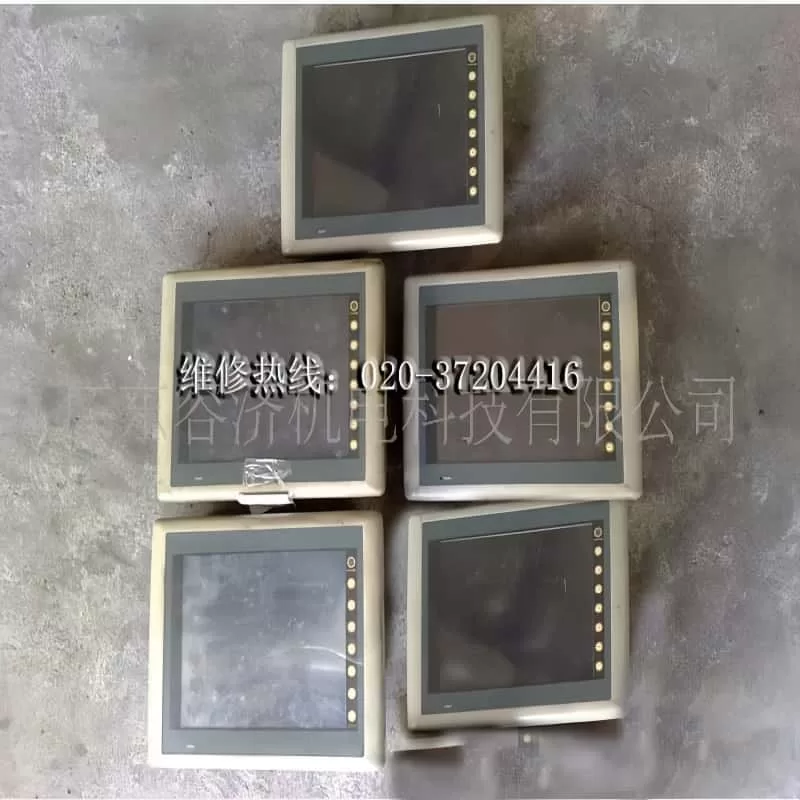
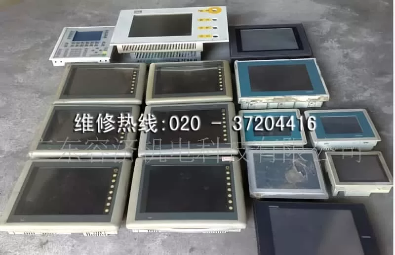
    At Rongji Electromechanical Company, we have repaired touch screens from numerous brands including Siemens, Proface, Mitsubishi, Fuji, Panasonic, OMRON, and many more. Our extensive experience and expertise enable us to provide reliable repair services for a wide variety of touch screen models.

    Common Touch Screen Problems We Solve

    • Unresponsive Touch Screen: If your touch screen is visible but cannot be touched or clicked, it may be due to a faulty touch panel. Our experts can replace the panel to restore functionality.
    • No Display: If your touch screen does not display anything and the indicator lights are off, it could be a power supply issue. We can diagnose and repair the problem to get your touch screen back up and running.
    • Black Screen: If your touch screen functions but displays a black screen, it may be due to a burned-out backlight tube. We can replace the tube to restore the display.
    • Distorted Image or Abnormal Colors: Issues with the LCD or connecting cables can cause distorted images or abnormal colors. Our technicians can diagnose and repair these issues to ensure clear and accurate display.
    • Communication Errors: If your touch screen displays a communication error and responds slowly to touch, it may be due to issues with the PLC or other connected devices. We can troubleshoot and repair the connection to ensure smooth communication.

    Choose Rongji Electromechanical Maintenance for reliable and professional touch screen repair services. Contact us today to learn more about our services and how we can help you keep your touch screens in optimal condition.

    Posted on Leave a comment

    Global Servo CNC maintenance center

    Global Servo CNC maintenance center,Professional maintenance of servo CNC systems

    Remember to contact Longi Electromechanical for any issues with servo and CNC systems!

    Servo systems differ from VFDs in that they offer higher precision and typically come with delicate encoders. Servo motors are synchronous motors with magnets inside, and if not handled carefully during disassembly and assembly, their original performance may not be restored. Additionally, different servo drivers cannot be used interchangeably with other servo motors. This means that during the repair of a servo driver, a corresponding servo motor and cable plug are required for proper testing. Similarly, repairing a servo motor also requires a matching servo driver for testing, which can pose challenges for many maintenance personnel.

    As for CNC (Computer Numerical Control) systems, most are embedded industrial computer types with closed control systems. Each manufacturer has its own design ideas, programming methods, wiring, and communication architectures, making them incompatible with one another.

    Longi Electromechanical Company has designed various styles of servo and CNC maintenance test benches to test the working conditions of different CNC systems, servo drivers, or servo motors. When servo systems encounter issues such as no display, phase loss, overvoltage, undervoltage, overcurrent, grounding, overload, module explosion, magnet loss, parameter errors, encoder failures, communication alarms, etc., the corresponding platform can be used to test and diagnose the problem.

    Repair Hotline: +8618028667265 Mr. Guo

    After resolving these issues, the servo system also needs to undergo a simulated load test to avoid problems such as overcurrent under load conditions, even if it performs well under no-load conditions. This ensures that the servo system is fully functional and ready for use in actual applications.

    For the CNC system, it is also necessary to conduct simulated operation before normal delivery to avoid any discrepancy with the on-site parameters. Currently, Rongji Electromechanical possesses hundreds of servo and CNC test benches, which can quickly identify problem areas and promptly resolve issues. With these advanced testing facilities, Longi Electromechanical ensures the smooth operation and reliability of the repaired equipment.

    The Servo and CNC Repair Center established by Longi Company currently has over 20 skilled and experienced maintenance engineers who specialize in providing repair services for different brands and specifications of servo and CNC systems. They implement tailored repair solutions for different maintenance projects, ensuring efficient and high-quality service for customers. By helping customers save valuable production time and reducing their maintenance costs, Rongji truly cares about the urgent needs of its customers and strives for common development and progress together.

    We have repaired the following brands of servo and CNC systems:

    Servo Systems

    • Lenze Servo Systems
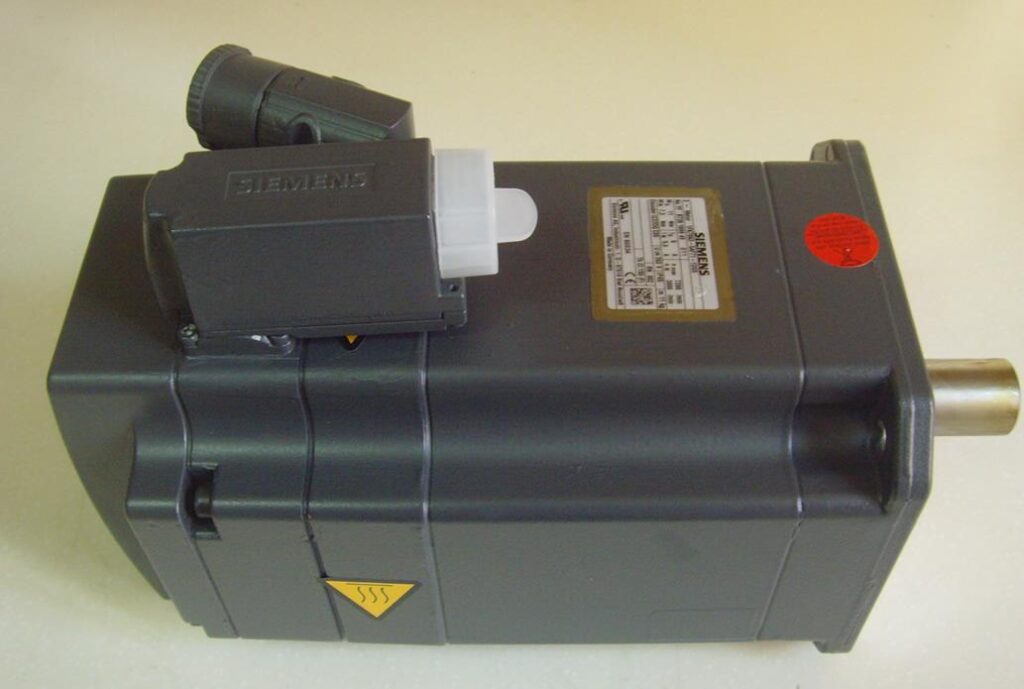
    • Siemens Servo Systems
    • Panasonic Servo Systems
    • Eurotherm Servo Systems
    • Yaskawa Servo Systems
    • Fuji Servo Systems
    • Delta Servo Systems
    • Omron Servo Systems
    • Fanuc Servo Systems
    • Moog Servo Systems
    • TECO Servo Systems
    • Norgren Servo Systems
    • SSB Servo Drive Systems
    • Hitachi Servo Systems
    • Toshiba Servo Systems
    • Denso Servo Systems
    • Parvex Servo Systems

    CNC Systems

    • Mitsubishi Servo Systems
    • Sanyo Servo Systems
    • Mitsubishi CNC (MITSUBISHI)
    • Fanuc CNC (FANUC)
    • Siemens CNC (SIEMENS)
    • Brother CNC (BROTHER)
    • Mazak CNC (MAZAK)
    • GSK (Guangzhou Numerical Control)
    • Huazhong Numerical Control
    • Fagor CNC
    • Heidenhain
    • Haas CNC
    • NUM (France)
    • Hurco (USA)
    • KND (Beijing KND Technology Co., Ltd.)
    • Leadshine
    • Syntec
    • Shenyang Machine Tool i5
      *凯恩帝 (KND)

    Note: Some of the brand names mentioned may be trademarks or registered trademarks of their respective owners. The listing here is for informational purposes only and does not imply any affiliation or endorsement by Rongji Electromechanical or any of the mentioned brands.

    Machine Tool Brands

    (1) European and American Machine Tools:

    • Gildemeister
    • Cincinnati
    • Fidia
    • Hardinge
    • Micron
    • Giddings
    • Fadal
    • Hermle
    • Pittler
    • Gleason
    • Thyssen Group
    • Mandelli
    • Sachman
    • Bridgeport
    • Hueller-Hille
    • Starrag
    • Heckert
    • Emag
    • Milltronics
    • Hass
    • Strojimport
    • Spinner
    • Parpas

    (2) Japanese and Korean Machine Tools:

    • Makino
    • Mazak
    • Okuma
    • Nigata
    • SNK
    • Koyo Machinery Industry
    • Hyundai Heavy Industries
    • Daewoo Machine Tool
    • Mori Seiki
    • Mectron

    (3) Taiwanese and Hong Kong Machine Tools:

    • Hardford
    • Yang Iron Machine Tool
    • Leadwell
    • Taichung Precision Machinery
    • Dick Lyons
    • Feeler
    • Chen Ho Iron Works
    • Chi Fa Machinery
    • Hunghsin Precision Machinery
    • Johnford
    • Kaofong Industrial
    • Tong-Tai Machinery
    • OUMA Technology
    • Yeongchin Machinery Industry
    • AWEA
    • Kaoming Precision Machinery
    • Jiate Machinery
    • Leeport (Hong Kong)
    • Protechnic (Hong Kong)

    (4) Chinese Mainland Machine Tools:

    • Guilin Machine Tool
    • Yunnan Machine Tool
    • Beijing No.2 Machine Tool Plant
    • Beijing No.3 Machine Tool Plant
    • Tianjin No.1 Machine Tool Plant
    • Shenyang No.1 Machine Tool Plant
    • Jinan No.1 Machine Tool Plant
    • Qinghai No.1 Machine Tool Plant
    • Changzhou Machine Tool Factory
    • Zongheng International (formerly Nantong Machine Tool)
    • Dahe Machine Tool Plant
    • Baoji Machine Tool Plant
    • Guilin No.2 Machine Tool Plant
    • Wanjia Machine Tool Co., Ltd.
    • Tianjin Delian Machine Tool Service Co., Ltd.

    Note: The list provided above is comprehensive but not exhaustive. Machine tool brands and manufacturers are constantly evolving, and new players may have emerged since the compilation of this list. Always refer to the latest industry updates for the most accurate information.

    Posted on Leave a comment

    Global Variable Frequency Drive (VFD) repair center

    “Longi Electromechanical” has more than 20 years of experience in industrial control maintenance, and is one of the earliest companies engaged in VFD repair. Equipped with artificial intelligence AI maintenance instruments, it specializes in emergency repair of various equipment, with high technical efficiency. It has repaired more than 200,000 units of equipment, including ultrasonic, robot, charging pile, inverter,Variable Frequency Drive (VFD), touch screen, servo, intelligent instrument, industrial control machine, PLC and other products. General problems can be repaired on the same day. LONGI promises you that “if it can’t be repaired, we won’t charge you”. And it provides lifelong maintenance service and free technical consultation for inspection! For urgent repair consultation, please call the contact number or add WHATSAPP maintenance hotline: +8618028667265 Mr. Guo

    From European and American brands to Japanese, Korean, and Taiwanese ones, until various domestic brands, we have repaired countless models and specifications of VFDs. In the process of serving our customers, we have continuously learned and accumulated maintenance experience to enhance our skills. We specialize not only in repairing VFDs but also in summarizing various maintenance experiences, elevating them to a theoretical level. We have published the book “VFD Maintenance Technology” and offered VFD maintenance training, thereby promoting the development of the VFD maintenance industry. Longi Electromechanical Company has repaired VFDs from the following brands:

    European and American Brands

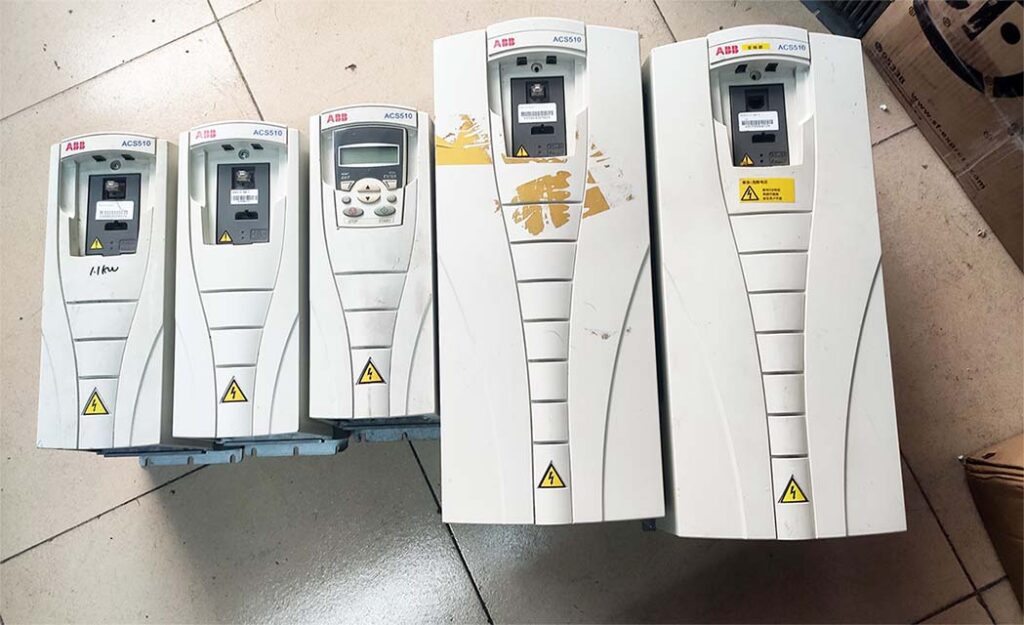
    ABB drives, SEW drives, LUST VFD, LENZE VSD, Schneider drives, CT drives, KEB VSD, Siemens drives, Eurotherm VFD, G.E. VFD, VACON VSD, Danfoss VFD, SIEI VFD, AB VFD, Emerson VFD, ROBICON VFD, Ansaldo VFD, Bosch Rexroth VSD, etc.

    Japanese Brands:

    Fuji INVERTER, Mitsubishi INVERTER, Yaskawa INVERTER, Omron INVERTER, Panasonic INVERTER, Toshiba INVERTER, Sumner INVERTER, Tooka INVERTER, Higashikawa INVERTER, Sanken INVERTER, Kasia INVERTER, Toyo INVERTER, Hitachi INVERTER, Meidensha INVERTER, etc.

    Taiwanese Brands:

    Oulin INVERTER, Delta INVERTER, Taian INVERTER, Teco INVERTER, Powtran INVERTER, Dongling INVERTER, Lijia INVERTER, Ningmao INVERTER, Sanji INVERTER, Hongquan INVERTER, Dongli INVERTER, Kaichi INVERTER, Shenghua INVERTER, Adlee INVERTER, Shihlin INVERTER, Teco INVERTER, Sanchuan INVERTER, Dongweiting INVERTER, Fuhua INVERTER, Taian INVERTER (note: Taian is repeated, possibly a mistake in the original list), Longxing INVERTER, Jiudesongyi INVERTER, Tend INVERTER, Chuangjie INVERTER, etc.

    Chinese Mainland brands:

    Senlan Inverter, Jialing Inverter, Yineng Inverter, Hailipu Inverter, Haili Inverter, Lebang Inverter, Xinnuo Inverter, Kemron Inverter, Alpha Inverter, Rifeng Inverter, Shidai Inverter, Bost Inverter, Gaobang Inverter, Kaituo Inverter, Sinus Inverter, Sepaxin Inverter, Huifeng Inverter, Saipu Inverter, Weier Inverter, Huawei Inverter, Ansheng Inverter, Anbangxin Inverter, Jiaxin Inverter, Ripu Inverter, Chint Inverter, Delixi Inverter, Sifang Inverter, Geli Te Inverter, Kangwo Inverter, Jina Inverter, Richuan Inverter, Weikeda Inverter, Oura Inverter, Sanjing Inverter, Jintian Inverter, Xilin Inverter, Delixi Inverter, Yingweiteng Inverter, Chunri Inverter, Xinjie, Kemron-Bong Inverter, Nihonye Inverter, Edison Inverter

    Other brands:
    Migao VFD, Rongqi VFD, Kaiqi VFD, Shiyunjie VFD, Huichuan VFD, Yuzhang VFD, Tianchong VFD, Rongshang Tongda VFD, LG VFD, Hyundai VFD, Daewoo VFD, Samsung VFD, etc.

    Longi Electromechanical Company specializes in the maintenance of VFDs and strictly requires its engineers to followlow standard operating procedures. Upon receiving a unit, the engineers carefully inspect its exterior and clarify any fault conditions with the customer before beginning work. Any removed circuit boards are cleaned using ultrasonic cleaning equipment. Repaired circuit boards are coated with high-temperature and high-pressure-resistant insulating paint, dried in a drying machine, and then reinstalled in the VFD, with measures taken to prevent corrosion and interference.

    The repaired VFD will undergo a simulated operation with load using a heavy-load test bench to avoid any potential issues that may arise under actual load conditions on site.

    When it comes to VFD maintenance, most cases are related to the equipment on site. Sometimes a standalone unit may have been repaired, but it doesn’t work properly when installed on site. In some cases, the problem lies with the system rather than the VFD itself. For such issues, if the customer requests on-site service, we will do our utmost to resolve the problem for them. If the location is far away, such as in another province, we can use tools like video conferencing and phone calls to allow our engineers to remotely diagnose and resolve the on-site issues for the customer.