Posted on Leave a comment

User Manual Guide for NETZSCH Thermal Conductivity Analyzer LF 467 Series

Principle and Features of the Instrument

The NETZSCH LF 467 series thermal conductivity analyzer uses the Laser Flash Method (LFA) to measure the thermal conductivity and diffusivity of materials. This method involves heating the front surface of a sample with a short energy pulse and measuring the resulting temperature change on the rear surface to calculate the thermal conductivity, specific heat, and thermal diffusivity【15†source】【21†source】. The basic formula is: λ(T)=a(T)⋅cp(T)⋅ρ(T)\lambda(T) = a(T) \cdot c_p(T) \cdot \rho(T)
Where:

  • λ\lambda: Thermal conductivity
  • aa: Thermal diffusivity
  • cpc_p: Specific heat capacity
  • ρ\rho: Density

Key Features of the Instrument:

  1. Wide Temperature Range: Supports testing from -100°C to 1250°C, applicable to various materials【15†source】【19†source】.
  2. High Data Acquisition Rate: Up to 2 MHz, enabling precise testing of thin films and highly conductive materials【21†source】.
  3. ZoomOptics Technology: Optimizes the field of view via software-controlled adjustable lenses, avoiding signal distortion【17†source】【21†source】.
  4. Automation: Supports testing of up to 16 samples simultaneously, improving experimental efficiency【15†source】.
Operating Procedures and Precautions

Operating Steps:

  1. Prepare the Sample: Ensure the sample is flat and has a thickness between 0.1 mm and 6 mm. Measure the thickness and spray graphite on the sample surface to improve signal quality【15†source】【20†source】.
  2. Load the Sample: Open the furnace chamber, place the sample in the designated tray positions, record the positions, and close the chamber【20†source】.
  3. Set the Atmosphere: Choose an inert, oxidizing, or vacuum atmosphere as needed, and ensure the gas flow is properly adjusted【21†source】.
  4. Run the Experiment: Use the dedicated software to set testing parameters, such as laser pulse energy and acquisition time, and start the test while monitoring data in real-time【15†source】【20†source】.
  5. Analyze Data: Upon completion, the software automatically calculates thermal conductivity and diffusivity and generates a test report【21†source】.

Precautions:

  • Ensure the furnace chamber is clean to avoid sample contamination or improper atmosphere.
  • Avoid direct contact with the instrument during high-temperature operations and wear protective gear.
  • Ensure the system is fully cooled before replacing cooling systems or adjusting gas flow【15†source】【20†source】.
Fault Codes, Their Meaning, and Solutions

Fault codes for the NETZSCH LF 467 series analyzer are typically displayed in the software interface. Below are common issues and solutions:

  1. E001: Laser Source Failure
    • Cause: Aging laser lamp or loose connection.
    • Solution: Check the laser lamp connection; replace the lamp if necessary【15†source】.
  2. E002: Furnace Overheating
    • Cause: Cooling system malfunction or furnace temperature control failure.
    • Solution: Inspect the cooling system for adequate liquid levels and unobstructed pipelines; adjust the temperature controller settings【19†source】【21†source】.
  3. E003: Data Acquisition Failure
    • Cause: Sensor malfunction or data acquisition card disconnection.
    • Solution: Reconnect the data acquisition card and ensure the sensor connections are secure【20†source】.
  4. E004: Vacuum Pressure Abnormality
    • Cause: Vacuum pump leakage or pressure sensor failure.
    • Solution: Inspect the vacuum pump’s seals and recalibrate the pressure sensor【15†source】.

Conclusion

The NETZSCH LF 467 series thermal conductivity analyzer, with its efficiency, precision, and intelligent design, provides robust tools for studying the thermal properties of materials. By mastering its operation and troubleshooting techniques, users can significantly enhance experimental efficiency and ensure data reliability. Always operate according to the user manual’s guidelines to prolong the instrument’s lifespan and ensure testing safety.

Posted on Leave a comment

Fault Diagnosis and Repair Methods for Xenon Flash Lamp Issues in the NETZSCH LFA 467 Laser Flash Analyzer

I. Overview of the Fault

The NETZSCH LFA 467 Laser Flash Analyzer is an advanced thermal properties testing instrument used to measure the thermal diffusivity and conductivity of materials. The xenon flash lamp is one of its core components, responsible for providing high-energy thermal pulses to samples for precise measurement.

If the xenon flash lamp fails to light, it directly prevents the generation of the required energy pulses, thereby affecting the measurement results. Users must quickly identify and troubleshoot the root cause of the fault to restore normal operation of the instrument.

This article will analyze the causes and repair methods for the xenon flash lamp failure in the LFA 467, focusing on the fault implications, possible reasons, specific troubleshooting methods, and repair steps.


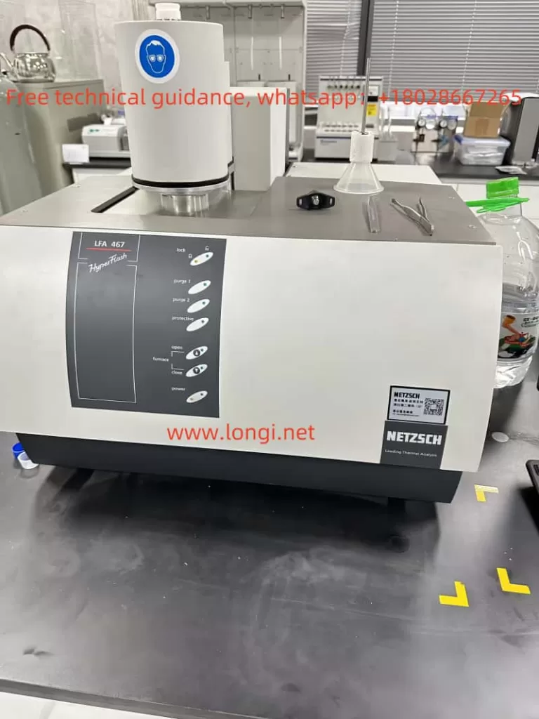
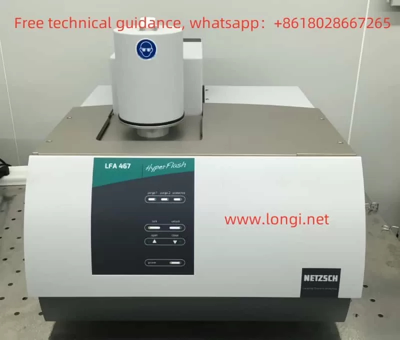
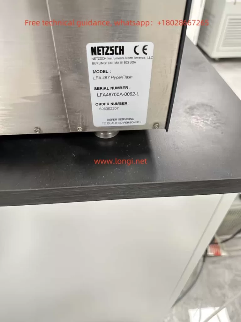
LFA 467 label

II. Implications and Possible Causes of the Fault

The failure of the xenon flash lamp to light indicates that the instrument has failed to complete the critical process of triggering and igniting the lamp. This issue may arise from the following factors:

  1. Lamp Aging or Damage: The xenon lamp is a high-voltage gas discharge light source, where internal xenon gas is ionized by a high-voltage trigger electrode. When the gas leaks or electrodes age, the lamp cannot conduct or light properly.
  2. Trigger Circuit Failure: The xenon lamp requires a high-voltage pulse (thousands to tens of thousands of volts) provided by a pulse transformer. A failure in the pulse transformer, the thyristor in the trigger circuit, or the driving signal can lead to triggering issues.
  3. Power Supply Circuit Anomalies: The xenon lamp’s anode and cathode require a stable DC high voltage (typically 300VDC). Faults in the rectifier bridge, storage electrolytic capacitors, or IGBT (Insulated Gate Bipolar Transistor) can prevent the lamp from receiving sufficient power.
  4. PWM Control Signal Issues: PWM (Pulse Width Modulation) signals regulate the power supply voltage to protect the lamp. Malfunctions in the driver circuit’s optocoupler, control chip (e.g., 74HC14D), or other components may result in excessive or insufficient lamp power.
  5. Insufficient Thermal Management: If key components (e.g., IGBT) overheat due to inadequate thermal dissipation, they may burn out, preventing the lamp from lighting.

LFA 467 physical object

III. Specific Troubleshooting Methods

The following steps can be taken to identify the fault source based on the above potential causes:

1. Test the Xenon Lamp
  • Method: Use a multimeter to measure the resistance between the xenon lamp’s main electrodes. If the resistance is near short-circuit or open-circuit levels, the lamp is damaged.
  • Alternative Test: Supply the lamp with approximately 300VDC externally while connecting a high-voltage trigger device (outputting 5kV-10kV) to the trigger electrode. If the lamp lights up, it is functional; otherwise, it should be replaced.
2. Check the Trigger Circuit
  • Pulse Transformer: Measure the primary and secondary resistance of the pulse transformer with a multimeter. Ensure the primary resistance (~0.23 Ω) and secondary resistance (~230 Ω) match design values. Replace the transformer if values are abnormal or open.
  • Thyristor: Measure the A-K and G-K resistance of the thyristor (e.g., TYN612MFP) to verify if leakage or a short-circuit exists. Replace the thyristor if anomalies are detected.
3. Check the Power Supply Circuit
  • Electrolytic Capacitors: Use a capacitance meter to test the capacity of the storage capacitors. Replace them if the capacity drops significantly or leakage is observed.
  • Rectifier Circuit: Inspect the rectifier bridge and related diodes for functionality. Use a multimeter to test forward and reverse resistance to confirm proper rectification.
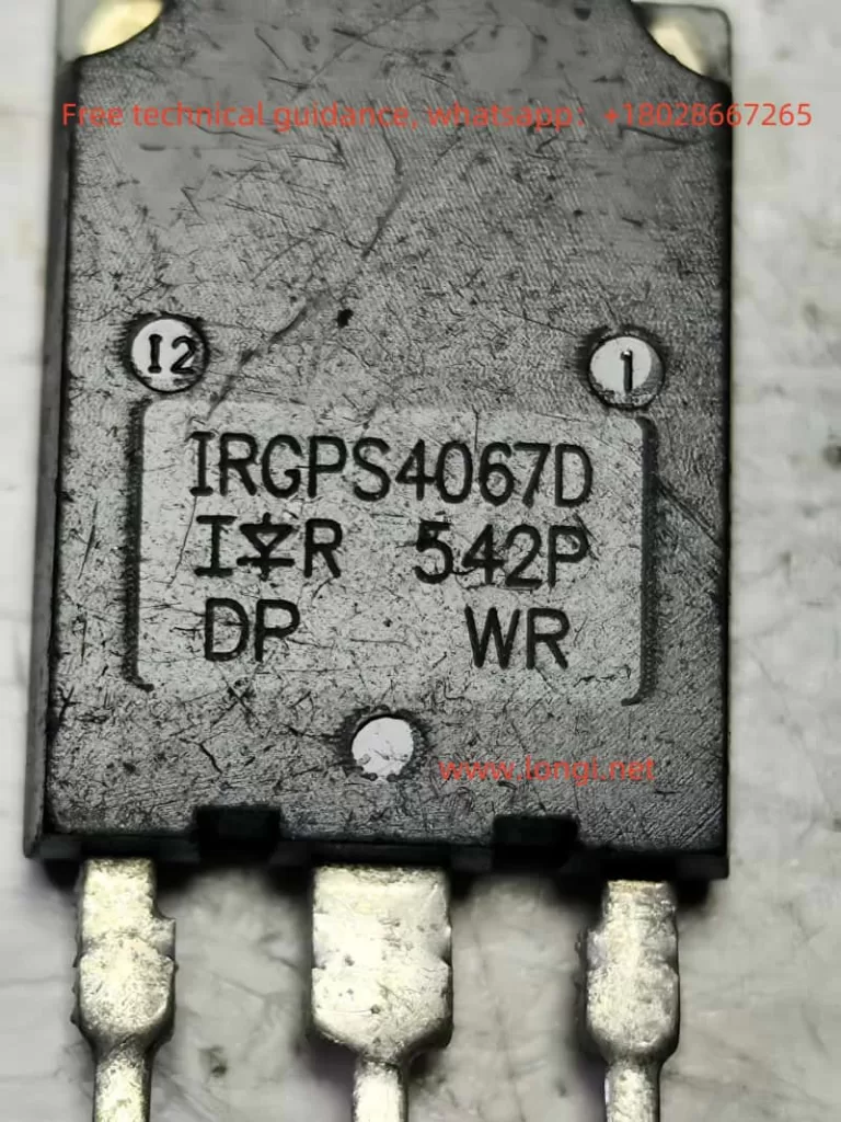
  • IGBT Status: If the IGBT (e.g., IRGPS4067D) is damaged, power delivery to the lamp may be interrupted. Measure the C-E (collector-emitter) resistance with a multimeter to determine its condition. Burnt IGBTs should be replaced immediately.
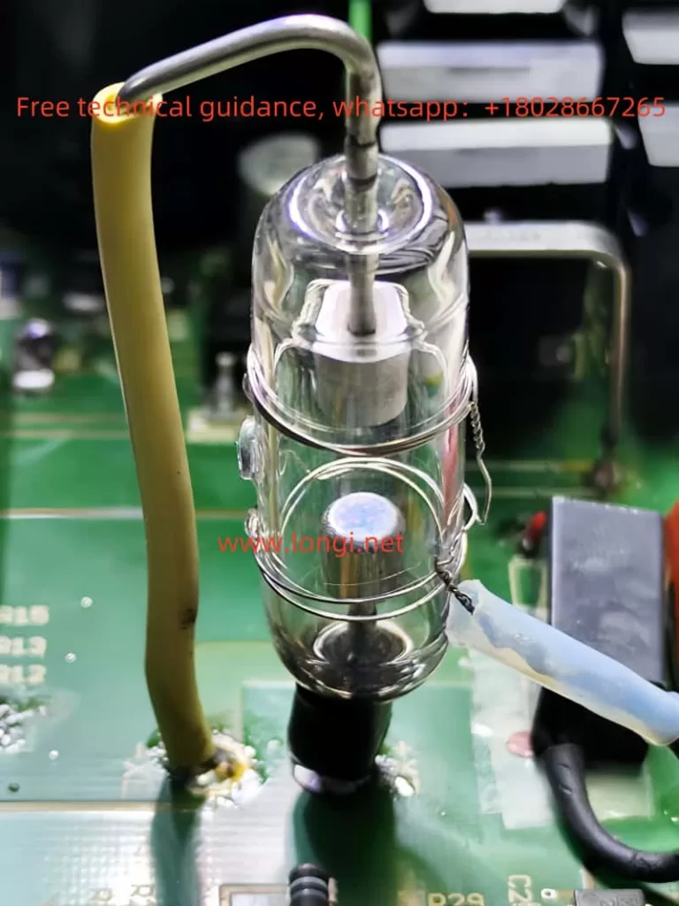
Xenon flash lamp
4. Check the Driver and Control Circuit
  • PWM Signal: Use an oscilloscope to examine the signal waveform of the optocoupler (e.g., AQY210LSX) and control chip (e.g., 74HC14D). Verify that the PWM duty cycle and frequency meet design requirements.
  • Optocoupler Test: Test whether the optocoupler’s input and output terminals conduct properly using a multimeter or a simple test circuit.
5. Inspect Thermal Management
  • Ensure the IGBT and thyristor’s heat sinks are properly attached, with evenly applied thermal paste.
  • Clean dust around the heat sinks and verify that cooling fans are operating correctly.

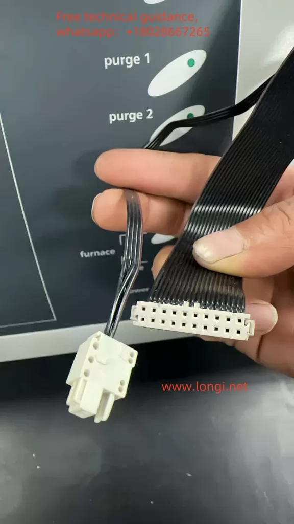
Xenon flash board plug

IV. Repair Methods and Practical Steps

Step 1: Replace Damaged Components

Replace confirmed faulty components based on the troubleshooting results, including the xenon lamp, pulse transformer, thyristor, IGBT, electrolytic capacitors, etc.

Step 2: Strengthen Circuit Protection
  1. Add RC Snubber Circuit: Install an RC snubber network (e.g., 10 Ω + 0.1µF) across the IGBT and thyristor to absorb voltage spikes and protect critical components.
  2. Add TVS Diodes: Integrate TVS diodes into the high-voltage rectifier circuit to prevent transient voltage surges from damaging the circuit.
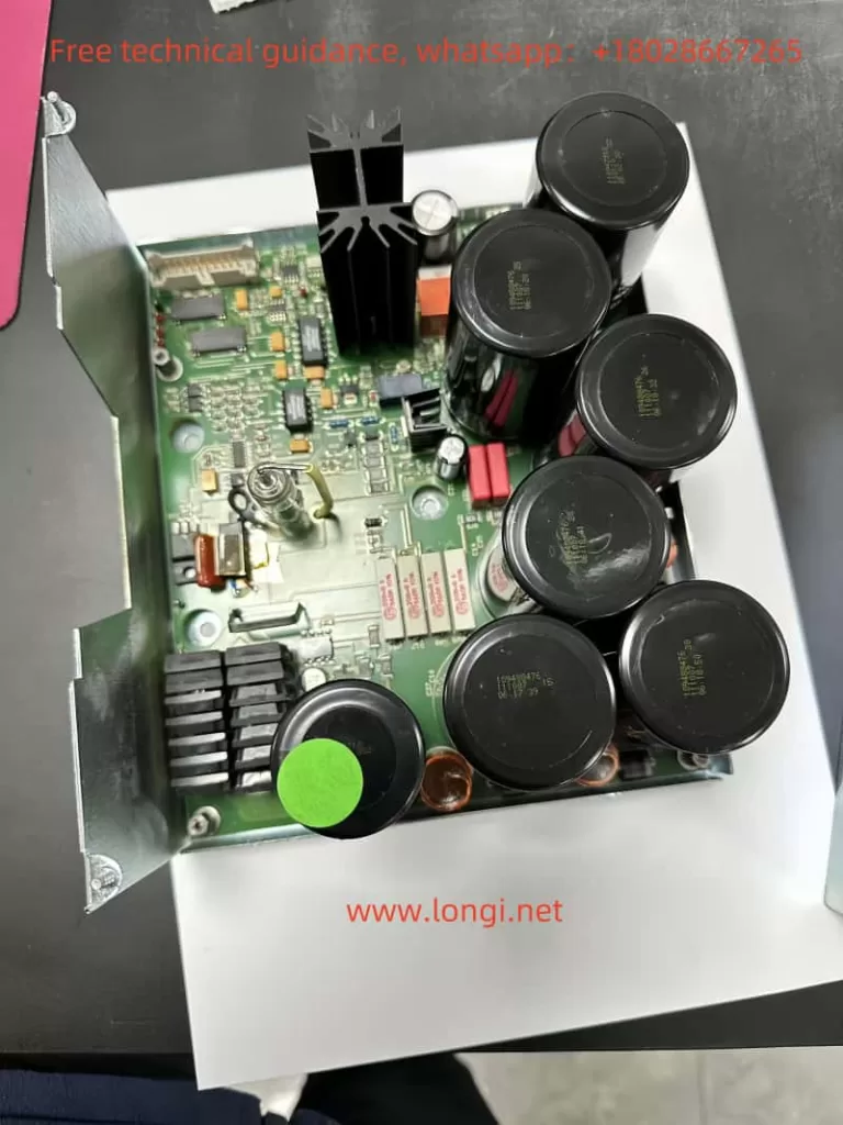
Xenon flash control board
Step 3: Optimize PWM Driver Circuit
  • Check and optimize the PWM signal’s duty cycle range to avoid excessively high or low output voltages.
  • Ensure the stability of control signals to prevent false triggering due to interference.
Step 4: Test and Debug
  • After replacing components, gradually power on the circuit to verify the functionality of the power supply.
  • Test the trigger circuit to ensure the pulse transformer outputs a normal high voltage.
  • Finally, connect and light the xenon lamp, observing its stable operation.

IRGPS4067D,Switching tube for controlling the anode voltage of xenon lamp

V. Conclusion and Recommendations

The xenon flash lamp in the NETZSCH LFA 467 Laser Flash Analyzer is a critical component, and its failure to light typically involves multiple circuit modules. Through systematic troubleshooting and repair, normal operation of the instrument can be quickly restored.

To prevent similar issues in the future, users are advised to perform regular maintenance on the circuit board, including cleaning heat sinks, inspecting critical components, and ensuring the instrument is not exposed to excessive voltage or current surges.

Scientific repair approaches and meticulous operations will help extend the instrument’s service life and ensure the accuracy of experimental results.

Posted on Leave a comment

User Manual Guide for NETZSCH LFA 427 Series Laser Thermal Diffusivity Measurement Instrument


Introduction

With the increasing demand for materials’ thermal properties in industrial and research fields, laser thermal diffusivity measurement instruments have become indispensable tools for researchers and engineers. The LFA 427 series laser thermal diffusivity measurement instrument, developed by NETZSCH, a German company, is one of the most advanced devices on the market. It is widely used for thermal diffusivity measurements of metals, ceramics, plastics, and other materials. This article will provide a detailed guide to the operation of the LFA 427 series, based on its user manual, covering its principles, features, usage methods, and troubleshooting approaches, to help users effectively operate this device.

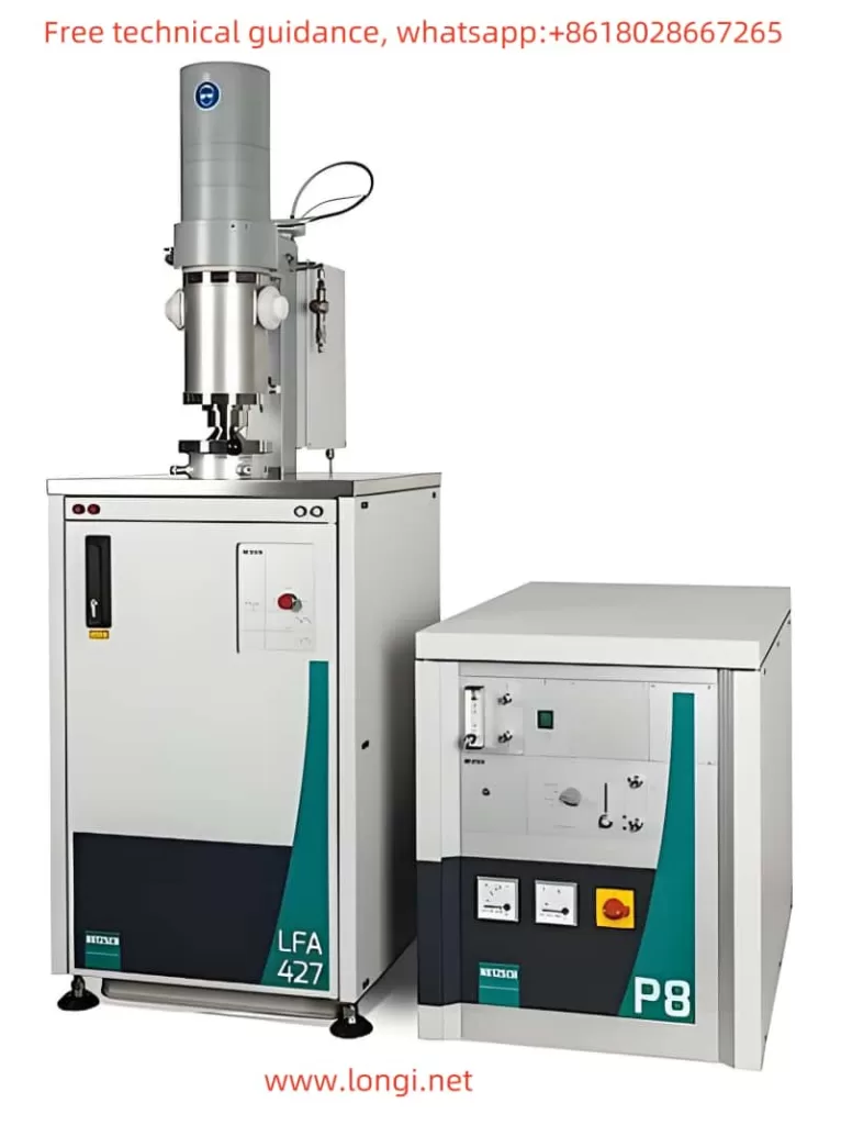
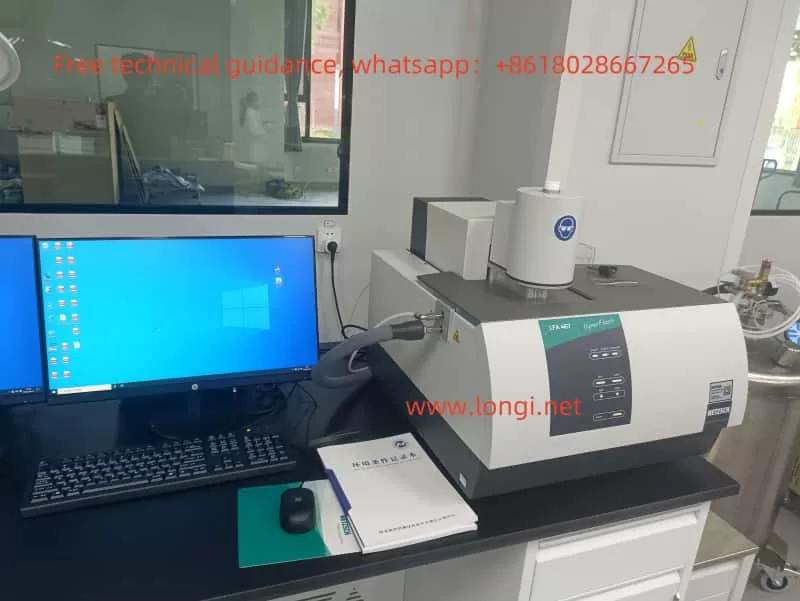
LFA 427 physical image

Principles and Features of the LFA 427 Series

Principle:
The LFA 427 series uses the Laser Flash Analysis (LFA) method for thermal diffusivity measurement. In this method, a short laser pulse is directed at the surface of the sample, causing rapid heating, which generates a thermal wave that propagates through the material. The temperature change on the opposite side of the sample is measured over time, allowing the thermal diffusivity to be calculated. This method is highly accurate and sensitive, making it suitable for a wide range of materials.

Features:

  1. High Precision and Stability: The LFA 427 series uses advanced sensor technology, providing precise measurements down to the micro-watt level, making it suitable for measuring extremely thin or small samples.
  2. Wide Application Range: Whether for high thermal conductivity metals, low conductivity ceramics, or complex composite materials, the LFA 427 can effectively measure their thermal diffusivity.
  3. Fast Response: With its rapid data collection and processing capabilities, the instrument can provide accurate results in a short amount of time.
  4. Automation: The LFA 427 series features an advanced automation system that allows users to easily set test parameters and monitor the test process through a computer interface, reducing human error.
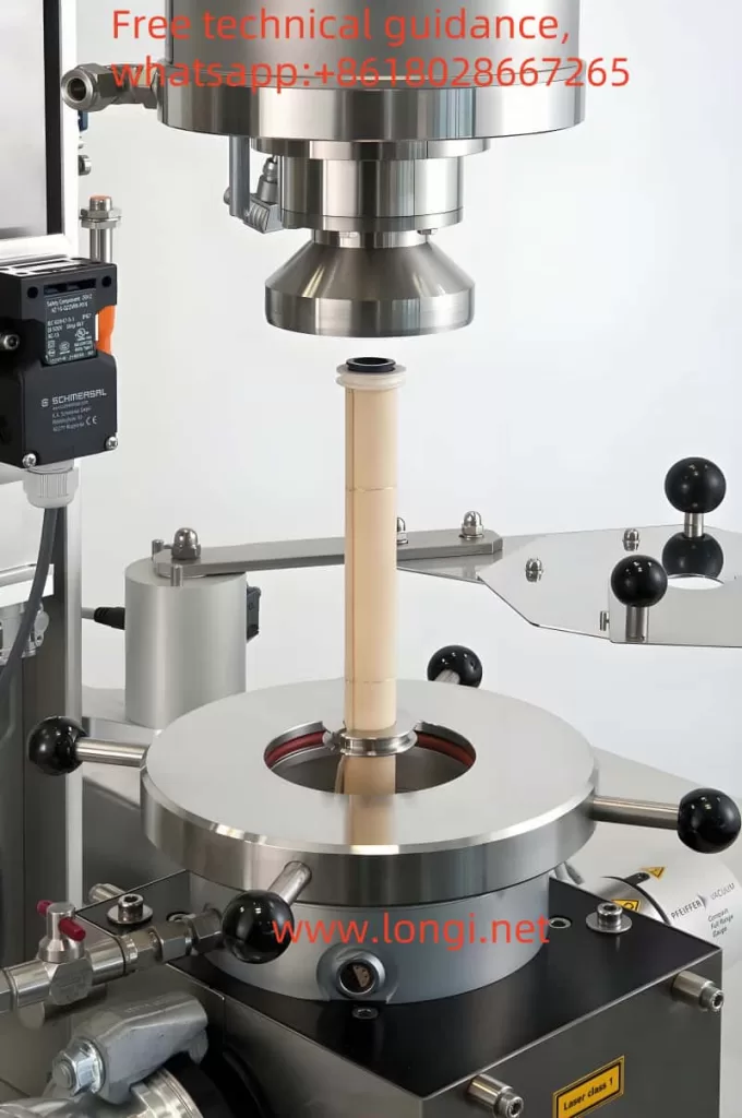
LFA 427 Test Diagram

How to Use the LFA 427 Series and Precautions

Usage Instructions:

  1. Instrument Setup: Place the LFA 427 on a stable workbench, ensuring the instrument is level to prevent external vibrations from affecting the measurement results.
  2. Sample Preparation: The sample surface should be smooth and uniform, free from bubbles, cracks, or irregularities. The sample’s thickness and weight must meet specific requirements.
  3. Instrument Settings: Connect the instrument to a computer and start the LFA 427 software. Set appropriate parameters, such as laser pulse energy and measurement time, based on the sample type. Select the correct measurement mode (single-sided or double-sided measurement).
  4. Measurement Process: Once the measurement starts, the instrument will automatically collect data and analyze it. Users can view the test results in real-time through the software interface.

Precautions:

  1. Environmental Conditions: The measurement environment should be free from extreme temperatures, high humidity, or strong electromagnetic interference to ensure accurate results.
  2. Sample Quality: The sample surface must be flat to ensure even laser exposure and accurate temperature response.
  3. Calibration and Maintenance: It is recommended to calibrate the instrument before each use to ensure measurement accuracy. Additionally, regularly clean the sensors and laser emitters to maintain optimal performance.

Fault Analysis and Troubleshooting Methods

Common Faults and Symptoms:

  1. Display Errors or No Display: The instrument does not display data or shows abnormal readings after startup.
  2. Unstable or Inaccurate Measurements: Measurement results fluctuate significantly or show noticeable deviation even under the same conditions.
  3. Instrument Won’t Start: The power is on, but the instrument does not start, and no display appears.

Fault Cause Analysis:

  1. Power Supply Issues: There could be loose connections or poor contact in the power supply line, preventing the instrument from starting.
  2. Temperature Sensor Malfunction: If the sensor is faulty, measurement results may be unstable or inaccurate.
  3. Environmental Interference: Strong electromagnetic interference or unstable temperature and humidity in the measurement environment may affect the accuracy of the results.
  4. Software Problems: Incorrect software settings or compatibility issues with the hardware could cause abnormal data collection.

Troubleshooting Methods:

  1. Check Power Connections: Ensure the power cable and socket are properly connected. Try using a different power cable or socket.
  2. Inspect and Replace Sensors: Regularly check the sensors for dirt or damage, and replace them if necessary.
  3. Optimize the Environment: Ensure the test area is stable, free from external vibrations, and maintains consistent temperature and humidity. Avoid operating in areas with strong electromagnetic noise.
  4. Software Updates and Reconfiguration: Ensure that the software is up to date, and recalibrate the instrument to rule out software configuration issues.

Conclusion

The NETZSCH LFA 427 series laser thermal diffusivity measurement instrument is a powerful tool for measuring the thermal properties of materials, offering high precision, stability, and versatility. By following proper operating procedures and performing regular maintenance, users can fully leverage its capabilities to obtain reliable data for research and industrial applications. It is essential to pay attention to sample preparation, environmental control, and instrument calibration to ensure accurate results. Additionally, being familiar with common faults and troubleshooting methods will help users efficiently resolve issues and extend the instrument’s lifespan.


Posted on Leave a comment

NETZSCH LFA 427 Laser Flash Apparatus “No Laser Pulse Detected” Fault Analysis and Repair Guide

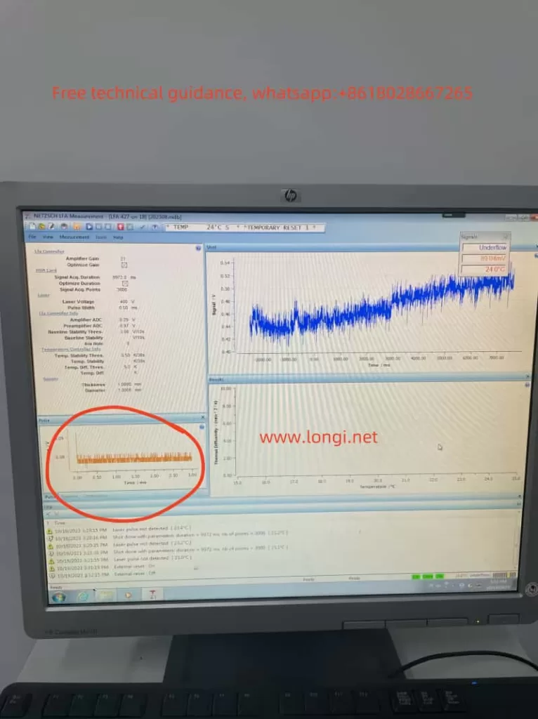
In the fields of materials science and thermal analysis, the NETZSCH LFA 427 Laser Flash Apparatus is a popular high-precision instrument. However, during use, the fault alarm “No Laser Pulse Detected” may sometimes occur, which not only affects the smooth progress of the measurement process but may also seriously impact the accuracy of experimental results. This article will delve into this fault, providing a detailed fault analysis and repair guide.

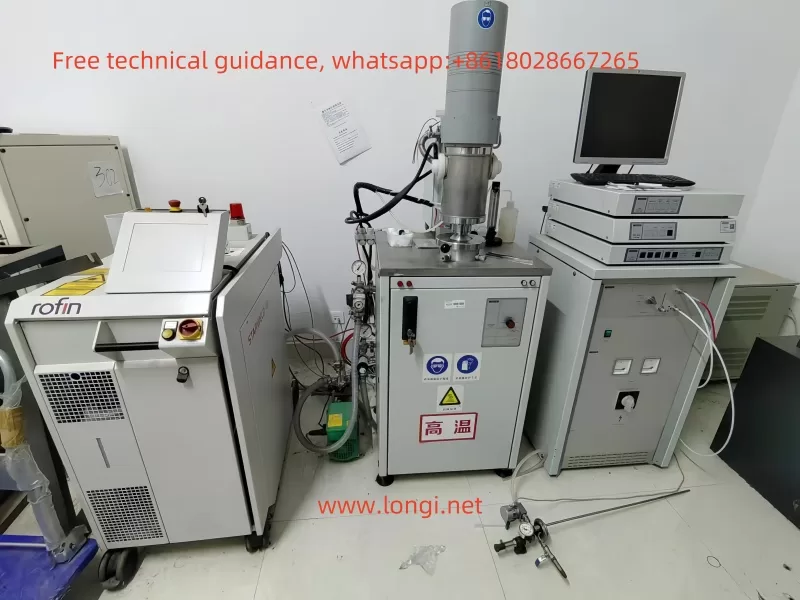
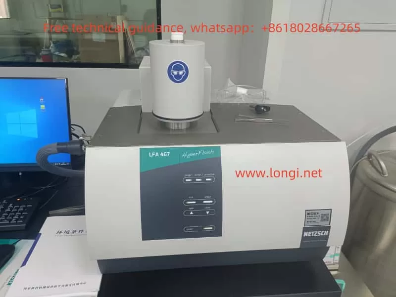
NETZSCH LFA 427 Laser Flash Apparatus

I. Description of Fault Phenomenon
When the NETZSCH LFA 427 Laser Flash Apparatus displays the “No Laser Pulse Detected” alarm, it is usually accompanied by abnormal waveform displays on the instrument interface, such as missing pulses or waveform distortion. Simultaneously, the temperature-time chart may also exhibit instability or abnormal fluctuations. These phenomena indicate that there is an issue with the instrument’s laser pulse detection system, preventing it from functioning normally.

II. Possible Fault Causes

  1. Unstable Laser Performance
    The laser is one of the core components of the Laser Flash Apparatus, and its performance directly affects the stability and accuracy of the laser pulses. If the laser power supply is unstable, internal components are aged or damaged, or the cooling system efficiency is reduced, it may lead to abnormal laser pulse output, triggering a fault alarm.
  2. Inaccurate Optical Path Alignment
    The optical path system of the Laser Flash Apparatus is complex, comprising multiple optical components and precise adjustment mechanisms. If the optical components are misaligned or loose, their surfaces are contaminated, or there are obstructions or reflective interferences in the optical path, it may prevent the laser pulses from being accurately transmitted to the detector, causing a fault.
  3. Reduced Detector Sensitivity
    The detector is a key component that receives laser pulses and converts them into electrical signals. If the detector itself is faulty, its surface is contaminated, the power supply is insufficient, or there are issues with the signal amplifier, it may reduce its sensitivity, making it unable to accurately capture laser pulses.
  4. Electrical Connection Issues
    The electrical connection system of the Laser Flash Apparatus includes multiple cables and connectors. If the cable connections are loose or broken, the signal lines are subjected to electromagnetic interference, or the contact at the connector is poor, it may result in unstable or lost transmission of the laser pulse signals.
  5. Software or Firmware Faults
    The measurement software and firmware are crucial for controlling the operation of the Laser Flash Apparatus. If the software parameters are incorrectly set, the firmware version is incompatible or has vulnerabilities, or the data acquisition module is faulty, it may cause the system to fail to correctly identify or record laser pulses.
  6. Environmental Factors
    Excessive fluctuations in ambient temperature or the presence of strong electromagnetic interference sources may also affect laser pulse detection. These factors may lead to unstable performance of the laser or detection system, triggering a fault alarm.
Waveform diagram and fault content when NETZSCH LFA 427 Laser Flash Apparatus is faulty

III. Specific Inspection Steps
To address the aforementioned possible fault causes, we can follow these steps for troubleshooting:

  1. Check Laser Status
    Use a multimeter to measure the voltage and current of the laser power supply, ensuring they meet the specifications.
    Inspect the power cord and connectors for integrity, ensuring they are not loose or damaged.
    Use a power meter to measure the laser’s output power and confirm it is within the normal range.
    Check the operation status of the cooling system to ensure proper heat dissipation.
  2. Verify Laser Pulses
    Manually trigger laser pulses under safe conditions and observe if the detector can receive the pulse signals.
    Use a laser observation tool to confirm if the laser is actually firing.
  3. Check Optical Path Alignment
    Clean all optical components using a lint-free cloth and cleaner.
    Adjust the positions of the optical components according to the optical path alignment guide.
    Inspect the optical path for physical damage or deformation, and replace damaged components if necessary.
  4. Verify Detector Function
    Ensure all cable connections between the detector and the main control system are secure.
    Test the detector’s response using laser pulses of known intensity.
    Clean the detector surface to ensure no contaminants affect its detection performance.
  5. Electrical Connections and Signal Integrity
    Inspect the integrity of all relevant cables, ensuring they are not damaged or worn.
    Use a multimeter to test the continuity of key connectors.
    Confirm that the signal cables are well-shielded to avoid electromagnetic interference.
  6. Software and Firmware Check
    Verify the laser and detector-related parameters in the measurement software.
    Check for updated versions of the software or firmware and install the latest versions.
    Review software logs or error reports for possible fault indications.
  7. Environmental Factor Assessment
    Confirm if the instrument’s operating environment temperature is within the specified range.
    Assess if there are strong electromagnetic sources in the surrounding environment and try to move the instrument away or shield it.

IV. Repair Suggestions

  1. Self-inspection and Maintenance
    If you have relevant technical knowledge and experience, you can follow the above inspection steps for troubleshooting and perform basic maintenance and adjustments, such as cleaning optical components, realigning the optical path, and replacing damaged cables.
  2. Contact Professional Technical Support
    If self-troubleshooting does not resolve the issue, it is recommended to contact NETZSCH’s authorized service center or technical support team. They have professional repair tools and knowledge to more accurately diagnose and fix the fault.
  3. Spare Parts Preparation
    To reduce repair time, it is advisable to prepare commonly used spare parts in advance, such as laser modules, detector components, and optical lenses. This allows for quick replacement when needed.
  4. Regular Maintenance Plan
    Develop and implement a regular maintenance and calibration plan to ensure the instrument is in optimal working condition. This includes regularly cleaning optical components, checking cable connections, and calibrating the detector. This can prevent potential faults and extend the instrument’s lifespan.

V. Preventive Measures
To reduce the occurrence of the “No Laser Pulse Detected” fault, the following preventive measures can be taken:

  1. Environmental Control
    Ensure the instrument operates in a stable, vibration-free environment with suitable temperature and humidity. Avoid external factors affecting instrument performance, such as temperature fluctuations and electromagnetic interference.
  2. Operator Training
    Ensure all operators receive adequate training to understand the correct operating procedures and basic maintenance methods. Reduce human operational errors and improve the instrument’s efficiency and accuracy.
  3. Record Keeping and Monitoring
    Maintain detailed maintenance and fault records, and regularly monitor key parameters. Promptly identify abnormal trends and take measures, such as adjusting instrument parameters and replacing aged components.

In summary, the “No Laser Pulse Detected” fault in the NETZSCH LFA 427 Laser Flash Apparatus can be caused by various reasons. By systematically inspecting the laser’s operating status, optical path alignment, detector function, and electrical connections, the fault range can be gradually narrowed down, and the specific cause identified. During the repair process, corresponding measures can be taken based on the specific situation to fix the issue and ensure the instrument resumes normal operation. Simultaneously, by implementing preventive measures and a regular maintenance plan, the occurrence of faults can be reduced, and the instrument’s lifespan can be extended.