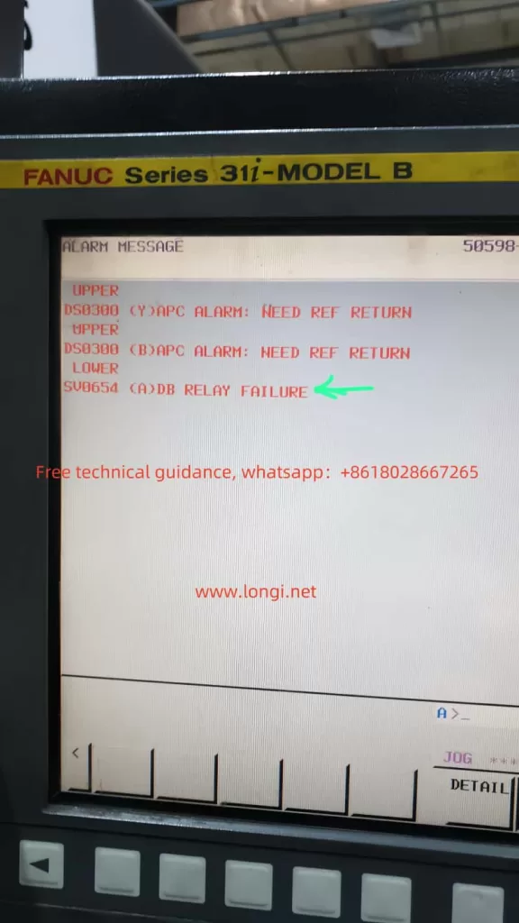
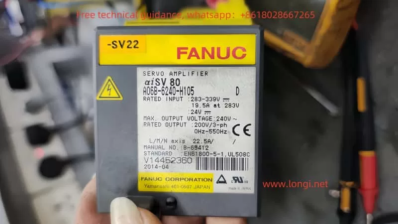
FANUC servo systems, widely used in industrial automation, are renowned for their reliability and precision. However, like any sophisticated equipment, they can experience faults that require systematic diagnosis and repair. This guide focuses on two common faults: “NEED REF RETURN” (Absolute Pulse Coder Alarm) and “DB RELAY FAILURE” (Dynamic Brake Relay Issue), along with general troubleshooting techniques.

1. “NEED REF RETURN” Alarm
Fault Description
The “NEED REF RETURN” alarm indicates that the absolute position data of the encoder is lost or the axis requires a reference return operation. This typically happens when:
- The encoder battery voltage is low or the battery has failed.
- The system loses its absolute position data due to a power interruption or improper initialization.
Repair Process
- Check the Encoder Battery:
- Replace the battery if its voltage is below the specified threshold (typically 3.6V for FANUC systems).
- Ensure the battery is replaced with the power ON to prevent loss of encoder data.
- Perform Reference Return:
- Access the machine’s control interface and initiate the reference return operation for the affected axes.
- Follow the machine tool builder’s specific procedures for homing operations.
- Inspect Encoder Wiring:
- Verify that the encoder cables are securely connected and free from damage.
- Check for continuity and signal integrity using a multimeter or oscilloscope if necessary.
- Reset the Alarm:
- Once the reference return is completed, reset the alarm via the machine control panel.

2. “DB RELAY FAILURE” Alarm
Fault Description
The “DB RELAY FAILURE” alarm indicates an issue with the Dynamic Brake (DB) relay, responsible for safely braking the motor during stop or emergency stop conditions. Possible causes include:
- A malfunctioning DB relay (burnt coil or damaged contacts).
- Faults in the relay driver circuit.
- Open or damaged connections in the DB circuit.
Repair Process
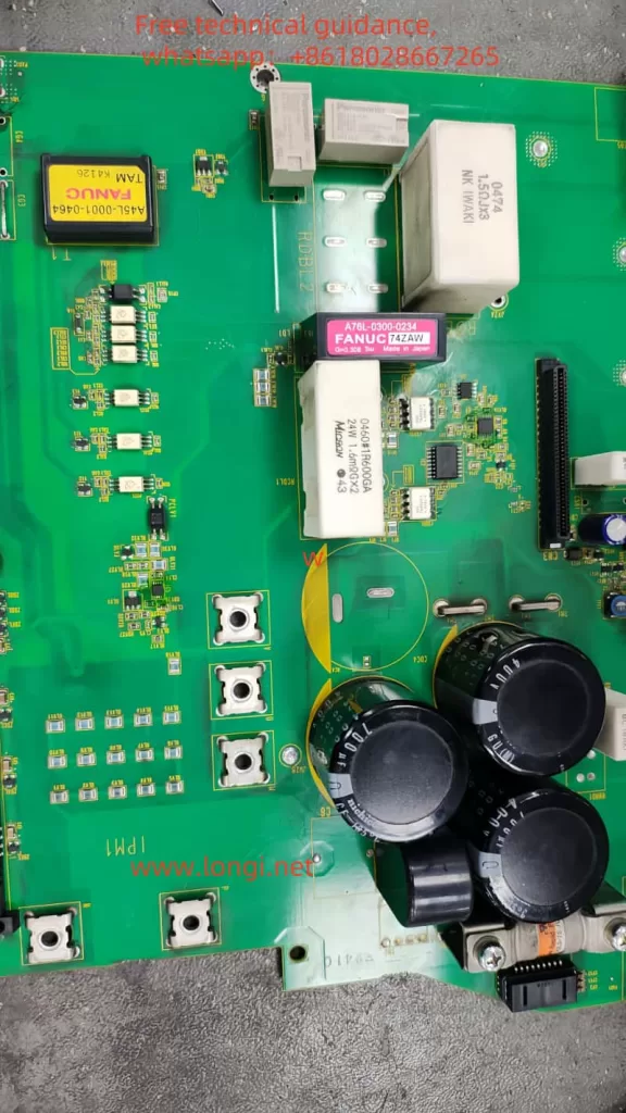
- Visual Inspection:
- Open the servo amplifier and inspect the relay for signs of burning, discoloration, or physical damage.
- Check the PCB for any visible defects such as burnt traces or damaged components.
- Test the DB Relay:
- Use a multimeter to measure the resistance of the relay coil. A functional relay typically has a specific resistance value (e.g., tens to hundreds of ohms). If open or short-circuited, the relay needs replacement.
- Inspect the relay contacts for proper operation and absence of welding or pitting.
- Inspect the Driver Circuit:
- Check the transistors or ICs driving the DB relay for shorts or open circuits.
- Use an oscilloscope to verify the control signal to the relay during operation.
- Verify DB Resistor and Wiring:
- Ensure the dynamic braking resistor is intact and its connections are secure.
- Measure the resistor’s value and compare it with the specifications.
- Replace Faulty Components:
- Replace the relay or driver components if faults are detected.
- Ensure replacement parts are genuine and match the original specifications.
- Reset and Test:
- After repairs, reset the system and perform operational tests to confirm the alarm is cleared and the DB relay functions correctly.

3. General Troubleshooting Techniques
LED Indicators
- Check the LED status on the servo amplifier front panel. LED patterns often provide diagnostic information about the amplifier’s status and errors.
Error Codes
- Refer to the system’s maintenance manual for detailed descriptions of error codes.
- FANUC manuals, such as the GFZ-65195EN/01, provide comprehensive troubleshooting steps for each alarm code.
Electrical Checks
- Measure power supply voltages to ensure they are within specified ranges.
- Inspect connectors, cables, and PCB traces for continuity and integrity.
Parameter Verification
- Confirm that the servo parameters are set correctly. Incorrect parameters can lead to operational issues and alarms.
4. Preventive Maintenance Tips
- Regular Battery Replacement:
- Schedule periodic checks and replacements for the encoder battery to avoid position loss.
- Keep Components Clean:
- Clean the servo amplifier and surrounding areas to prevent dust and debris accumulation.
- Inspect Wiring:
- Regularly inspect cables and connectors for wear, corrosion, or loose connections.
- Follow Manufacturer Guidelines:
- Always adhere to FANUC’s maintenance and operational guidelines for optimal system performance.

Conclusion
By understanding the causes and systematic repair methods for alarms like “NEED REF RETURN” and “DB RELAY FAILURE,” maintenance engineers can ensure minimal downtime and enhanced reliability of FANUC servo systems. Regular preventive maintenance further helps in avoiding recurring issues and extending the life of these critical components.
Comprehensive Guide to FANUC Servo System Troubleshooting and Repair
FANUC servo systems, widely used in industrial automation, are renowned for their reliability and precision. However, like any sophisticated equipment, they can experience faults that require systematic diagnosis and repair. This guide focuses on two common faults: “NEED REF RETURN” (Absolute Pulse Coder Alarm) and “DB RELAY FAILURE” (Dynamic Brake Relay Issue), along with general troubleshooting techniques.
1. “NEED REF RETURN” Alarm
Fault Description
The “NEED REF RETURN” alarm indicates that the absolute position data of the encoder is lost or the axis requires a reference return operation. This typically happens when:
- The encoder battery voltage is low or the battery has failed.
- The system loses its absolute position data due to a power interruption or improper initialization.
Repair Process
- Check the Encoder Battery:
- Replace the battery if its voltage is below the specified threshold (typically 3.6V for FANUC systems).
- Ensure the battery is replaced with the power ON to prevent loss of encoder data.
- Perform Reference Return:
- Access the machine’s control interface and initiate the reference return operation for the affected axes.
- Follow the machine tool builder’s specific procedures for homing operations.
- Inspect Encoder Wiring:
- Verify that the encoder cables are securely connected and free from damage.
- Check for continuity and signal integrity using a multimeter or oscilloscope if necessary.
- Reset the Alarm:
- Once the reference return is completed, reset the alarm via the machine control panel.
2. “DB RELAY FAILURE” Alarm
Fault Description
The “DB RELAY FAILURE” alarm indicates an issue with the Dynamic Brake (DB) relay, responsible for safely braking the motor during stop or emergency stop conditions. Possible causes include:
- A malfunctioning DB relay (burnt coil or damaged contacts).
- Faults in the relay driver circuit.
- Open or damaged connections in the DB circuit.
Repair Process
- Visual Inspection:
- Open the servo amplifier and inspect the relay for signs of burning, discoloration, or physical damage.
- Check the PCB for any visible defects such as burnt traces or damaged components.
- Test the DB Relay:
- Use a multimeter to measure the resistance of the relay coil. A functional relay typically has a specific resistance value (e.g., tens to hundreds of ohms). If open or short-circuited, the relay needs replacement.
- Inspect the relay contacts for proper operation and absence of welding or pitting.
- Inspect the Driver Circuit:
- Check the transistors or ICs driving the DB relay for shorts or open circuits.
- Use an oscilloscope to verify the control signal to the relay during operation.
- Verify DB Resistor and Wiring:
- Ensure the dynamic braking resistor is intact and its connections are secure.
- Measure the resistor’s value and compare it with the specifications.
- Replace Faulty Components:
- Replace the relay or driver components if faults are detected.
- Ensure replacement parts are genuine and match the original specifications.
- Reset and Test:
- After repairs, reset the system and perform operational tests to confirm the alarm is cleared and the DB relay functions correctly.
3. General Troubleshooting Techniques
LED Indicators
- Check the LED status on the servo amplifier front panel. LED patterns often provide diagnostic information about the amplifier’s status and errors.
Error Codes
- Refer to the system’s maintenance manual for detailed descriptions of error codes.
- FANUC manuals, such as the GFZ-65195EN/01, provide comprehensive troubleshooting steps for each alarm code.
Electrical Checks
- Measure power supply voltages to ensure they are within specified ranges.
- Inspect connectors, cables, and PCB traces for continuity and integrity.
Parameter Verification
- Confirm that the servo parameters are set correctly. Incorrect parameters can lead to operational issues and alarms.
4. Preventive Maintenance Tips
- Regular Battery Replacement:
- Schedule periodic checks and replacements for the encoder battery to avoid position loss.
- Keep Components Clean:
- Clean the servo amplifier and surrounding areas to prevent dust and debris accumulation.
- Inspect Wiring:
- Regularly inspect cables and connectors for wear, corrosion, or loose connections.
- Follow Manufacturer Guidelines:
- Always adhere to FANUC’s maintenance and operational guidelines for optimal system performance.
Conclusion
By understanding the causes and systematic repair methods for alarms like “NEED REF RETURN” and “DB RELAY FAILURE,” maintenance engineers can ensure minimal downtime and enhanced reliability of FANUC servo systems. Regular preventive maintenance further helps in avoiding recurring issues and extending the life of these critical components.
