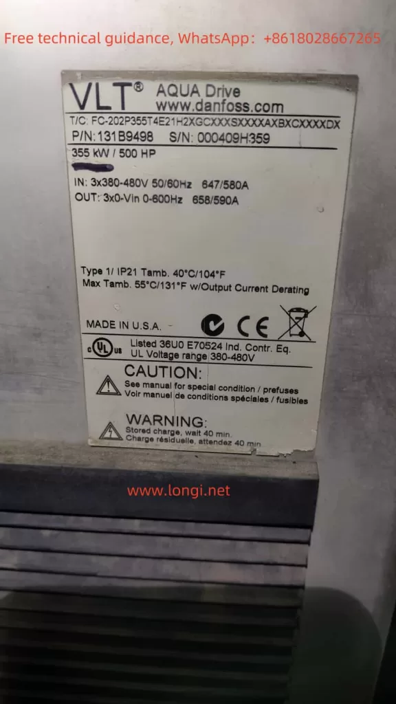
I. Introduction to the Danfoss Frequency Converter FC202 Operation Panel Functions
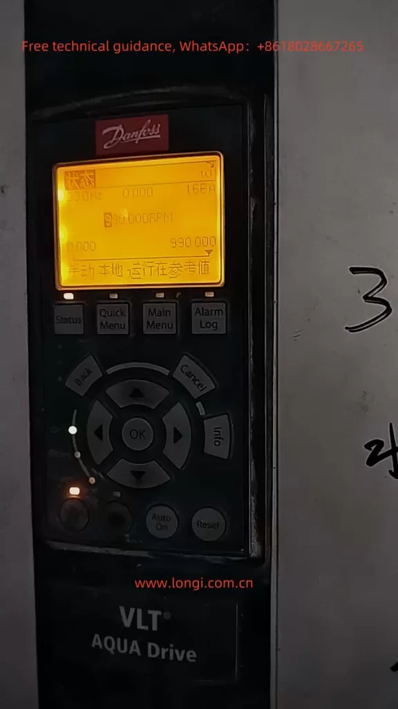
The Danfoss Frequency Converter FC202 series boasts a powerful operation panel that includes both a Graphical Local Control Panel (GLCP) and a Numerical Local Control Panel (NLCP). These control panels provide extensive status displays, parameter settings, and fault alarm functions, enabling users to easily monitor and control the operating status of the frequency converter.

1.1 Monitoring Parameters for Water/Wastewater Applications (Parameter Group 22)
When monitoring water/wastewater applications, users can set and monitor relevant parameters by accessing parameter group 22 of the frequency converter. Specific steps are as follows:
- Enter Parameter Group 22: First, press the [Quick Menu] button on the panel, then use the navigation keys to select “Function Set-up”, followed by “Application Functions”, and finally enter parameter group 22.
- Set and Monitor Parameters: In parameter group 22, users can set and monitor key parameters such as low power detection, low speed detection, no-flow functions, and dry pump detection. For example, parameter 22-20 can be used to enable automatic low power settings, and parameter 22-23 can be used to select the operation mode (sleep mode or warning message) when the no-flow function is activated.
1.2 Encrypting and Locking Parameters
To prevent unauthorized parameter modifications, users can encrypt and lock the frequency converter parameters. Specific steps are as follows:
- Enter Password Settings: In parameter group 0, select parameter 0-60 (Extended Menu Password) or parameter 0-65 (Personal Menu Password) to set the password.
- Lock Parameters: After setting the password, users can set the frequency converter to “Password Protected” mode via parameter 14-22 (Operating Mode). At this point, only users who enter the correct password can modify the parameters.
1.3 Restoring Factory Default Settings
When users need to restore the frequency converter parameters to their factory default settings, they can achieve this through the following steps:
- Power Cycle: First, disconnect the main power supply of the frequency converter and wait for a period before reconnecting it.
- Initialize Settings: After the frequency converter is powered on again, press the relevant buttons on the panel (the specific buttons vary depending on the panel type) to enter initialization mode, and then follow the on-screen prompts to complete the initialization operation. At this point, all parameters of the frequency converter will be restored to their factory default settings.

II. Forward/Reverse Control via Terminals and External Potentiometer Frequency Adjustment
2.1 Forward/Reverse Control via Terminals
To achieve forward/reverse control via terminals, users need to follow these wiring and parameter setting steps:
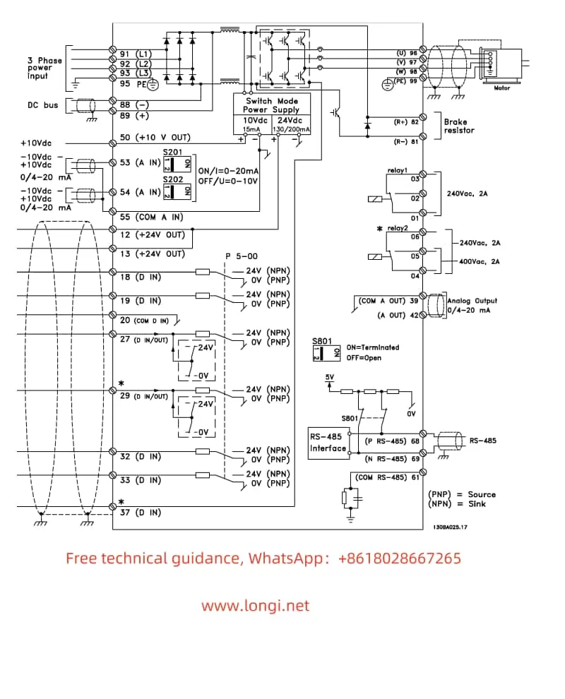
- Wiring: Connect the signal wires for forward and reverse control to the corresponding control terminals of the frequency converter (the specific terminal numbers vary depending on the model).
- Parameter Settings: Enter parameter group 5, select the digital input parameters (such as 5-10 and 5-11), and set the corresponding terminals to forward and reverse functions.
2.2 External Potentiometer Frequency Adjustment
To achieve external potentiometer frequency adjustment, users need to follow these wiring and parameter setting steps:
- Wiring: Connect the output signal wire of the external potentiometer to the analog input terminal of the frequency converter (such as terminal 53). At the same time, ensure that the power supply for the potentiometer is correctly connected.
- Parameter Settings: Enter parameter group 6, select the analog input parameters (such as 6-10 and 6-11), and set the input voltage range and calibration value for terminal 53. Then, in parameter group 3, select the reference value source parameter (such as 3-15) and set the reference value source to analog input terminal 53.

III. Fault Codes and Solutions
The Danfoss Frequency Converter FC202 series provides a wealth of fault codes to help users quickly locate and resolve faults. Below are some common fault codes, their meanings, and solutions:
3.1 Common Fault Codes and Meanings
- Alarm 1: 10V Voltage Low. Indicates that the voltage at control card terminal 50 is below 10V.
- Alarm 2: Disconnection Fault. Indicates that the signal on a certain analog input is below 50% of the minimum value set for that input.
- Alarm 4: Main Power Phase Loss. Indicates that a phase of the power supply is missing or the grid voltage is unstable.
- Alarm 9: Inverter Overload. Indicates that the inverter has shut down due to overload (excessively high current for an extended period).
- Alarm 12: Torque Limit. Indicates that the torque exceeds the set torque limit value.
3.2 Solutions
- For Alarm 1: Check the wiring and load condition of terminal 50 to ensure stable voltage and do not exceed the maximum load.
- For Alarm 2: Check the wiring and signal source of the analog input terminal to ensure proper operation.
- For Alarm 4: Check the power supply voltage and current of the frequency converter for stability and inspect the power line for any open circuits or short circuits.
- For Alarm 9: Check whether the motor is overloaded or has mechanical faults and adjust the current limit parameter of the frequency converter.
- For Alarm 12: Check whether the load exceeds the carrying capacity of the frequency converter and adjust the torque limit parameter.
IV. Conclusion
The Danfoss Frequency Converter FC202 Series User Manual provides detailed operation guides and parameter setting instructions, enabling users to easily monitor and control the operating status of the frequency converter. By setting parameters and wiring correctly, users can achieve various control functions of the frequency converter, such as forward/reverse control and external potentiometer frequency adjustment. At the same time, users can quickly locate and resolve fault issues by consulting fault codes and solutions. These features make the Danfoss Frequency Converter FC202 series an ideal choice for applications in water/wastewater and other fields.
