
As an important part of Siemens automation solutions, Siemens G120 series inverters are designed for high-performance applications. This series of inverters not only supports a wide range of motor types (including asynchronous motors, synchronous motors and servo motors), but also has excellent dynamic response capabilities and a rich set of functions, which can meet various needs from simple speed control to complex positioning control.
In the field of industrial automation, Siemens G120 series inverters are widely used in various motor control applications due to their high performance, high reliability and easy integration. This article combines multiple professional materials to provide engineers with a detailed Siemens G120 series inverter commissioning guide to help everyone better master the commissioning skills of this key equipment.
A、 BOP-2 operation panel description
The BOP-2 basic control interface is cleverly placed at the top of the control module. It plays a key role in inverter commissioning, operating status monitoring, and specific parameter configuration. This operation panel is unique and adopts a dual-line display design: the upper line focuses on displaying the specific values of the parameters, which is intuitive and clear; the lower line corresponds to the clear name of the parameters, which is convenient for users to quickly identify and operate. It is particularly worth mentioning that BOP-2 allows users to easily copy the various parameters of the inverter to the operation interface, and when necessary, easily download these parameters in batches to the inverters of the same series, greatly improving work efficiency and data management flexibility.
- As shown in Figure 1, the BOP2 operation interface of the G120 inverter is detailed, and its main components include:
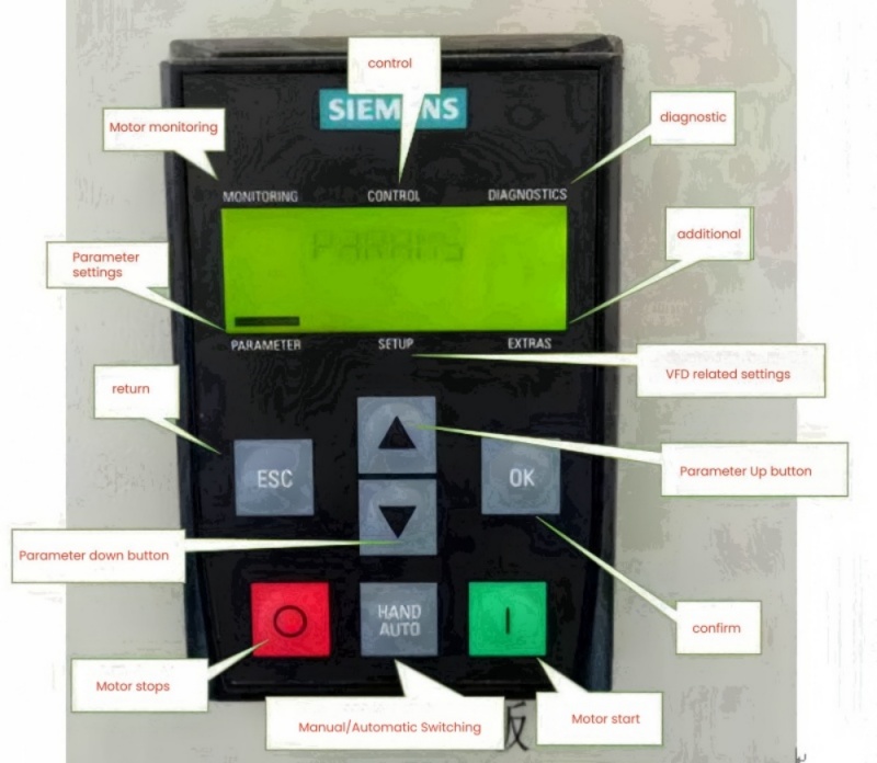
1. Motor Monitoring: This area focuses on real-time status monitoring of the motor, ensuring that users can instantly obtain key indicators of motor operation.
2. Control Operations: This section provides direct control of the inverter and the connected motor, allowing users to flexibly adjust the operating status.
3. Fault Diagnosis Area (Diagnostic Analysis): Specially used to identify and display possible system errors or abnormal conditions, so as to quickly locate the problem and handle it.
4. Parameter Settings: This area allows users to adjust and optimize the inverter parameters according to actual needs to achieve the best working performance and efficiency.
5. Setup Configuration: Focuses on the configuration management of the inverter itself, including network settings, security parameters, etc., to ensure stable operation of the equipment and compliance with safety standards.
6. Extra Features: Provides a series of additional practical functions or advanced settings to meet specific applications or user preferences.
(B)The hardware layout of the operation panel is equipped with multiple intuitive and easy-to-use buttons, as shown in Figure 2, including:
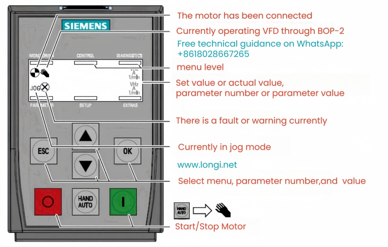
1. Escape key (ESC): used to exit the current operation or return to the previous menu.
2. Confirm button (OK): Execute the current selection or confirm the modified settings.
3. Mode switch key (HAND/AUTO): allows the user to easily switch between manual control mode and automatic operation mode.
4. Direction control keys (↑/↓): Used to move the cursor up and down in the menu and select the desired option.
5. Green start button: represents the command to start the motor safely, ensuring that the motor is started under safe conditions.
6. Red stop button: used to immediately stop the motor in an emergency to ensure the safety of personnel and equipment.
This design not only improves the convenience of operation, but also enhances the user’s ability to control the operating status of the inverter.
B、Quick debug mode operation
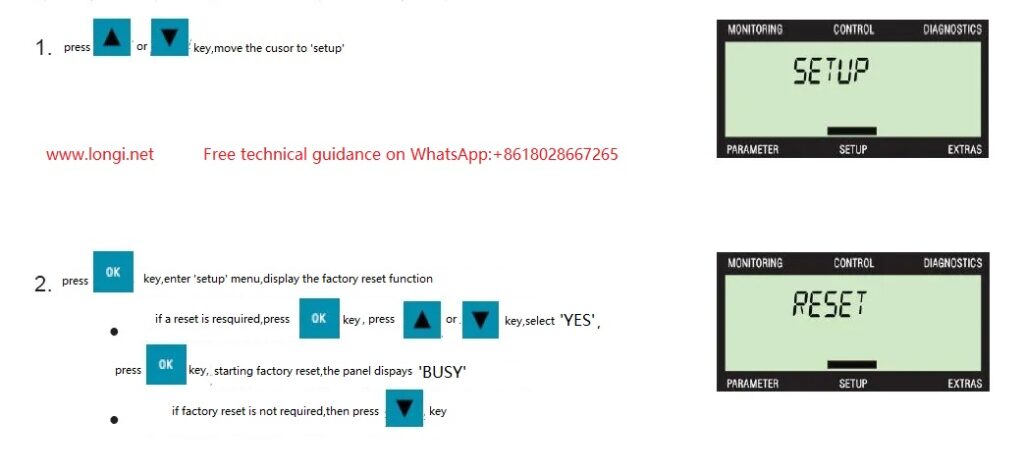
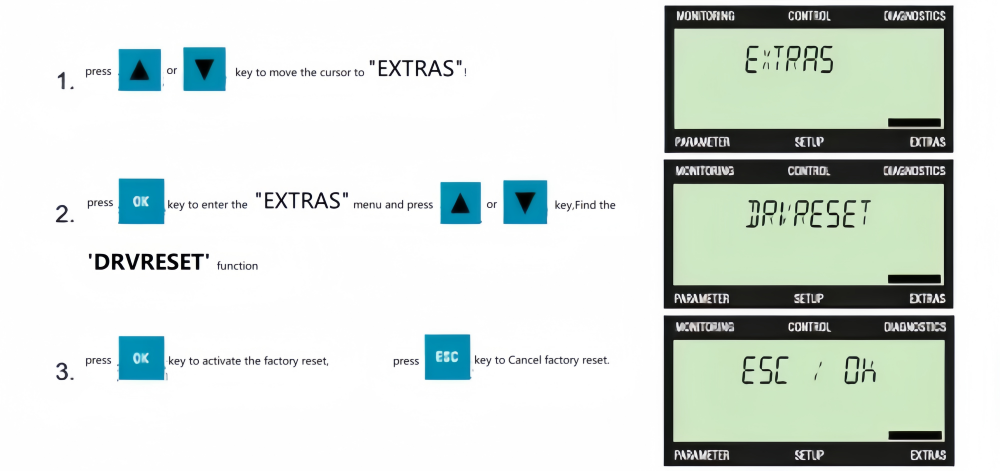
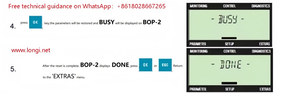
When starting up the inverter for the first time, the first step is to reset its parameters to factory settings. By navigating to the “setup” menu and confirming the “reset” operation, a selection box will pop up, showing the two options of “no” and “yes”. After explicitly selecting “yes” and confirming, the inverter will automatically initialize and return to the default configuration state. This step is to eliminate all existing motor-related configurations, ensure a pure test environment, avoid any potential unnecessary parameters from interfering with the normal operation of the inverter and motor on the test bench, and lay a stable foundation for subsequent debugging.
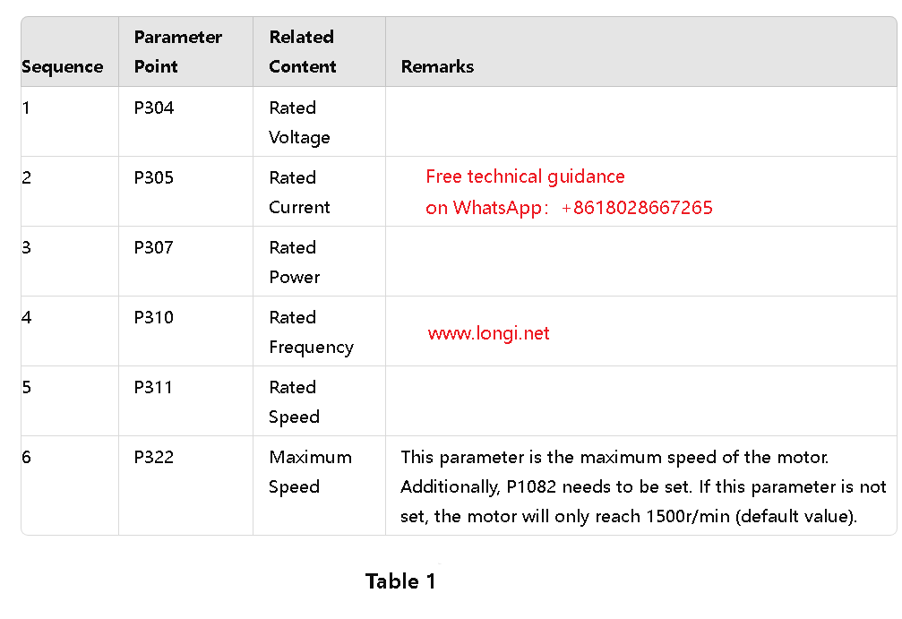
After completing the reset, there is no need to perform a power-off restart operation. Jump directly to the “parameter” interface, where you will see two options: “standard” and “expert”. Select to enter the “standard” level, first set P10=1, and then accurately configure various related parameters based on the motor nameplate information and refer to Table 1.
Then, set the P1900 parameter to 1 to start the dynamic self-learning process of the motor. Then, adjust P10 back to 0. Press the “esc” key to return to the main interface, and then tap the “HANDAUTO” key. The hand icon representing the manual mode will appear on the screen. At this time, use the ↑ key to manually set the target speed of the motor. The recommended setting value is about 50 rpm. Then, press the green motor start button, and the motor will enter the self-learning state. During this period, the screen will display the “MOTID” logo, and the motor and inverter may make some noises, which are all normal reactions.
When the motor identification and self-learning process is successfully completed, the error message X that may have existed will automatically disappear, indicating that the motor’s rapid commissioning phase has been successfully completed. At this point, the user can flexibly set the motor speed through the BOP-2 operation panel to achieve manual control of the rotation without having to power off again.
It is worth noting that in order to ensure that all settings are saved, it is necessary to re-enter the “standard” mode after completing the settings and set the P971 parameter to 1. This step is crucial because it ensures that the configured parameters can be retained even after the inverter is powered off and restarted, avoiding the frequent flashing of the inverter green light RDY (indicating that the parameters are not set correctly, affecting the operation of the motor), while also ensuring that the motor can continue to accept manual control. In addition, during the motor self-learning period, please maintain a proper distance to prevent accidents.
C、Quick debugging mode graphic specific operation process
The key to achieving quick start-up and stable operation of the motor lies in the accurate configuration of a series of core parameters, including the performance setting of the motor, the selection of the inverter command receiving source, and the clarification of the speed control source. This series of operations together builds an efficient and convenient motor commissioning process. With the help of BOP-2 (Basic Operation Panel) for quick commissioning, the specific steps can be summarized as follows:
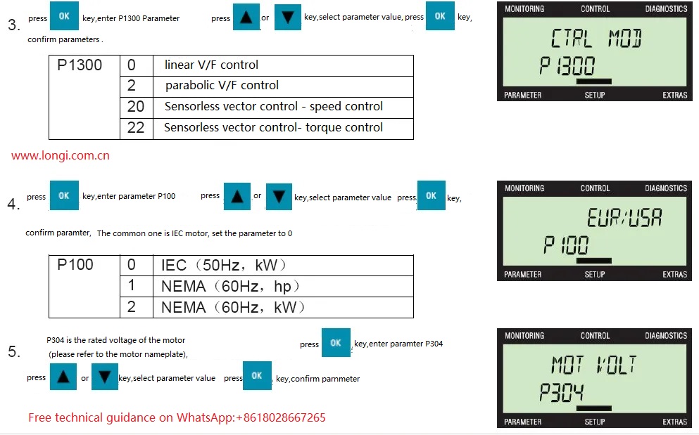
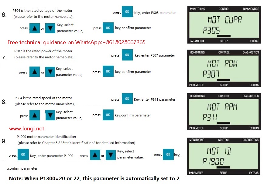
During the quick commissioning process, if parameter P1900 is configured to a non-zero value, after the commissioning is completed, the inverter will immediately trigger the A07991 alarm message, clearly indicating that the motor data identification process has been activated and is in standby state, waiting for further start instructions. This step is an important part of ensuring the matching degree between the motor and the inverter and optimizing performance. Users should refer to Section 5.2 “Static Identification” in the inverter manual to understand the details and precautions of this process in detail so as to smoothly perform subsequent operations.
D、Specific method flow for setting parameters
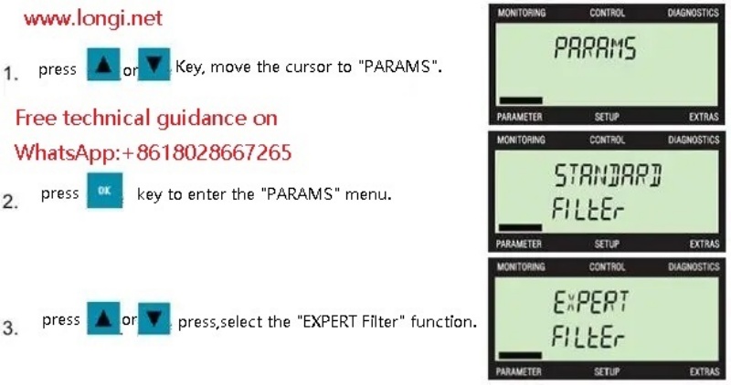
Through the BOP-2 interface, users can easily adjust various parameters. The specific operations are located in the “PARAMS” (parameter setting) or “SETUP” (configuration) menu. Simply modify the required parameter value.
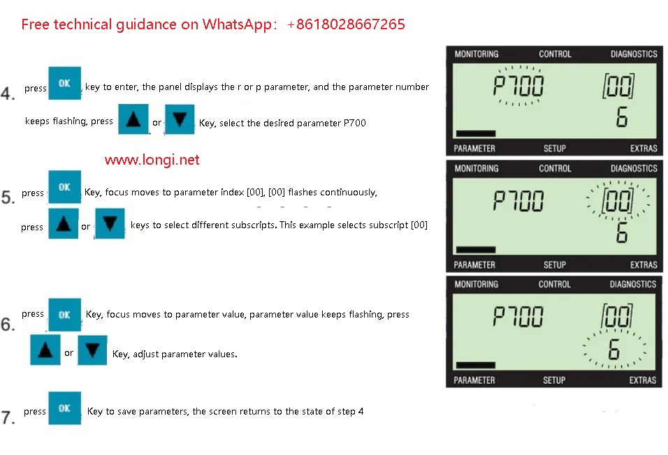
1. Select parameter number:

2.To modify a parameter value:

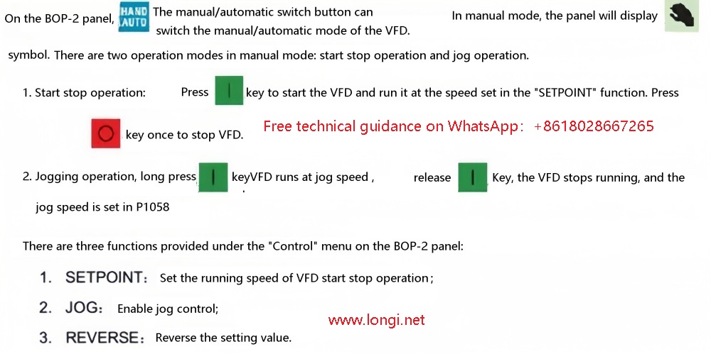
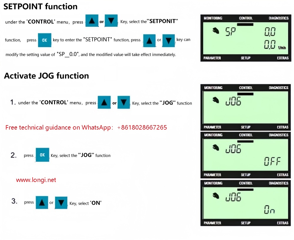
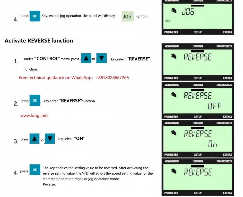
E、BOP-2 Manual Mode
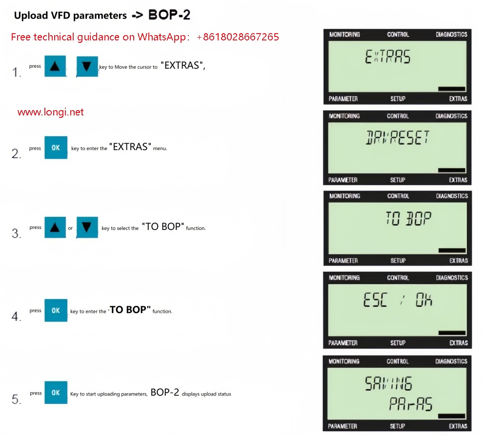
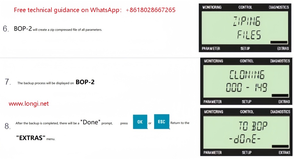
F、Upload parameters from VFD to BOP-2 panel
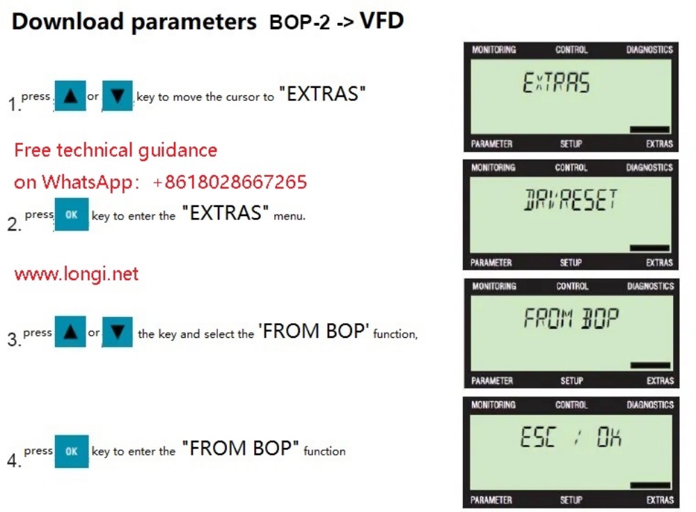
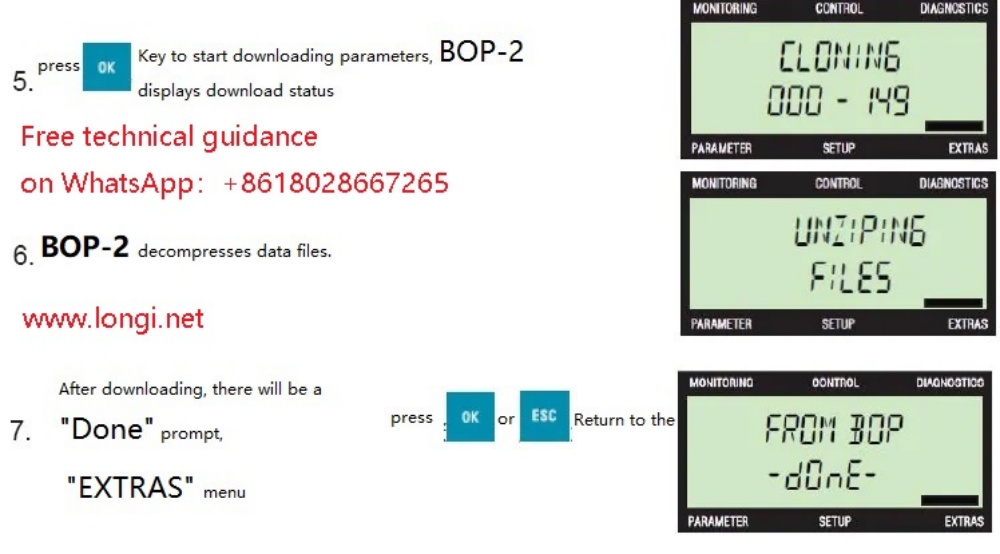
G、Download parameters from BOP-2 panel to VFD
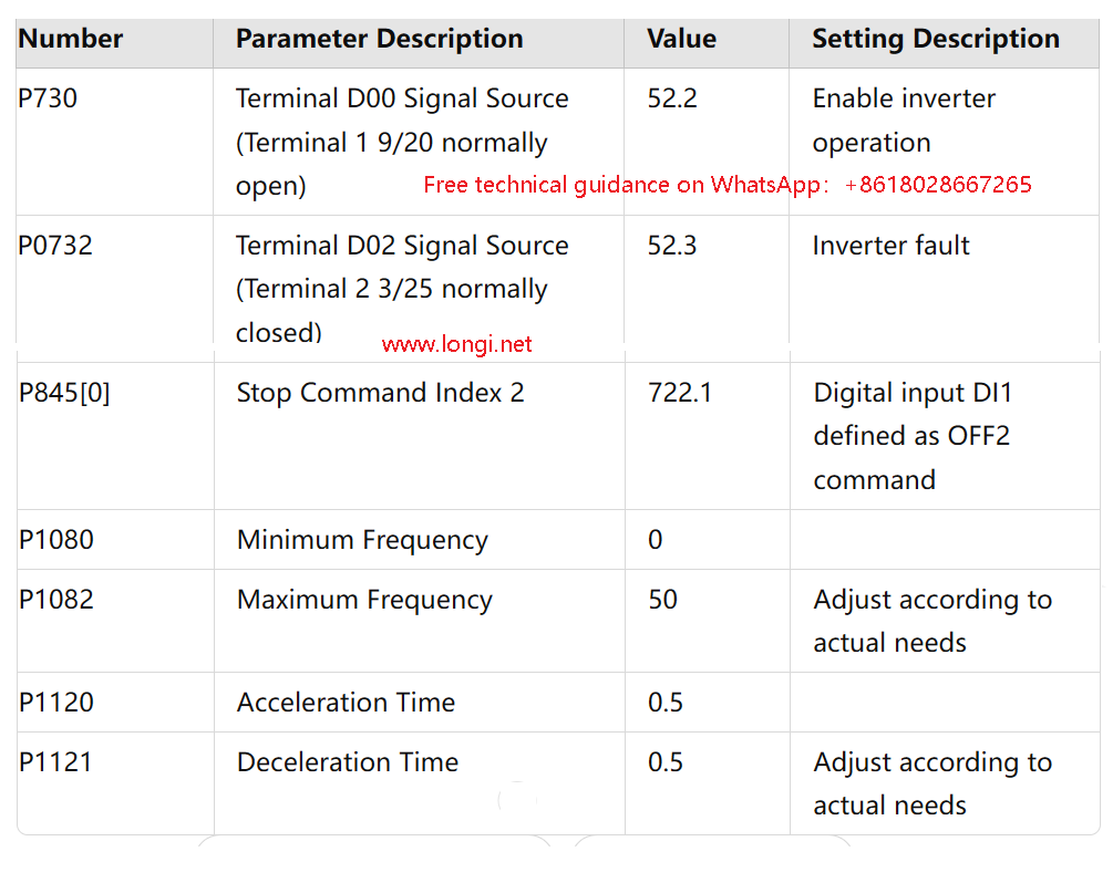
H、Main parameter settings
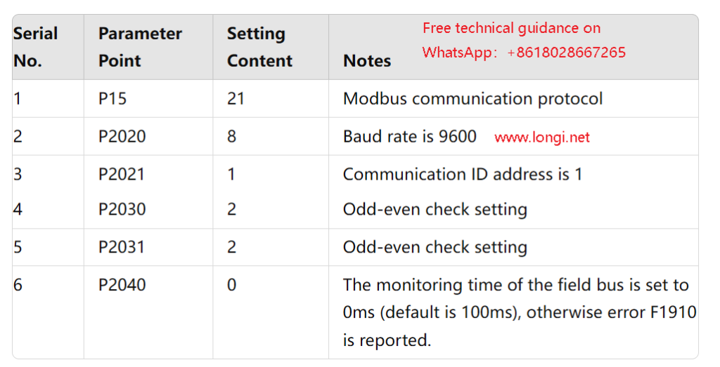
I、Communication parameter settings
After the motor acceleration debugging process is successfully completed, the next step is the key step of the communication configuration link. Entering the “parameter” interface, two major paths are presented in front of you: one is “standard” (standard mode), which is suitable for basic and broad needs; the other is “expert” (expert mode), which unlocks deeper customization and extended parameter options. When you step into the “expert” hall, you need to accurately adjust the parameters closely related to communication and other advanced settings one by one according to the carefully prepared Table 3 (parameter configuration guide). It is worth noting that there is no need to touch the P10 parameter (that is, the start switch P10=1 for motor quick debugging) at this time, because it has been properly set in the previous debugging stage, laying a solid foundation for the subsequent communication configuration.
After completing the setting of all parameters, the next necessary maintenance step is to power off the inverter and then restart the device. When restarting the inverter, in order to ensure that the system is stable and smoothly transitions to the new configuration state, the recommended restart interval should not be shorter than one minute. This waiting time gives the system enough buffering and reset opportunities.
During the period when the inverter is powered off, you can make full use of the time to carefully check the configuration of the inverter on the OPC (operation control panel or host control system), including but not limited to the serial port number, baud rate setting and device address confirmation. These steps are crucial to ensure seamless connection of the communication link.
After the inverter restarts and runs stably, you will find that the communication between the inverter and OPC has been successfully established, and the data transmission between the two will become smooth and unimpeded, laying a solid foundation for the subsequent automated control process.