
Simplified Debugging Guide for Siemens 400 Series (420/430/440) VFD Drives
Debugging a Siemens 400 series Variable Frequency Drive (VFD), specifically models 420, 430, and 440, can initially seem daunting due to the multitude of parameters and unfamiliar symbols on the operation panel. However, with a structured approach, even newcomers can quickly master the basics and get these drives running efficiently. This guide will outline a straightforward method for debugging, focusing on essential functions like start/stop control and frequency adjustment, along with some tips for PID operation and parameter adjustment.
Initial Setup and Terminal Connections
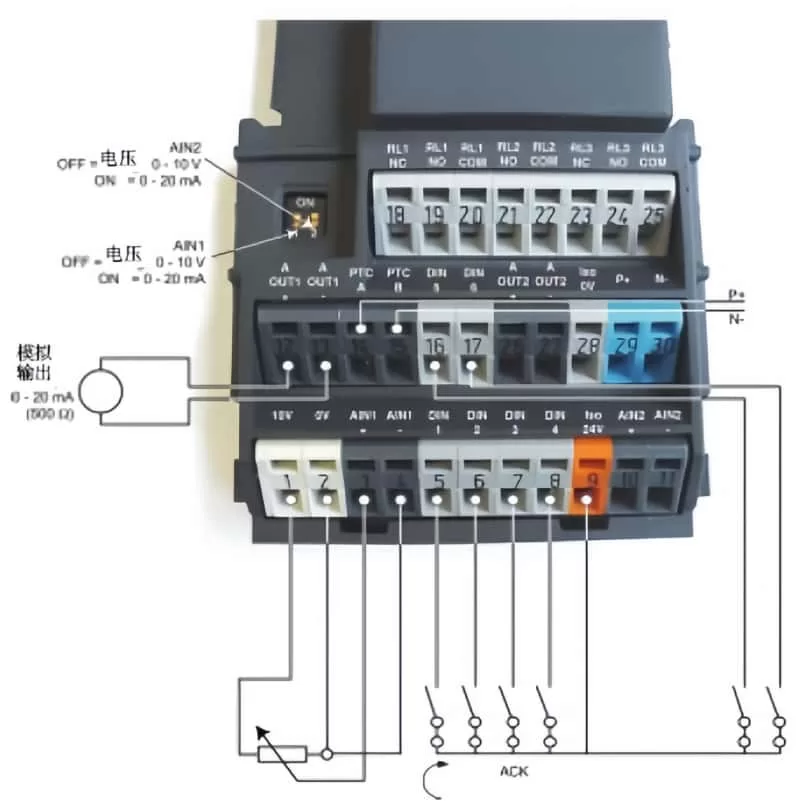
Before diving into the parameter settings, ensure that the terminal wires are properly connected. For basic operation, you’ll need to connect five wires:
- Start/Stop Switch: Connect between terminals 5 and 9.
- Potentiometer for Frequency Adjustment: Short-circuit terminals 2 and 4, then connect wires from terminals 1, 3, and 4 to the potentiometer, with terminal 3 connected to the center head.
Understanding Operation Panel Keys
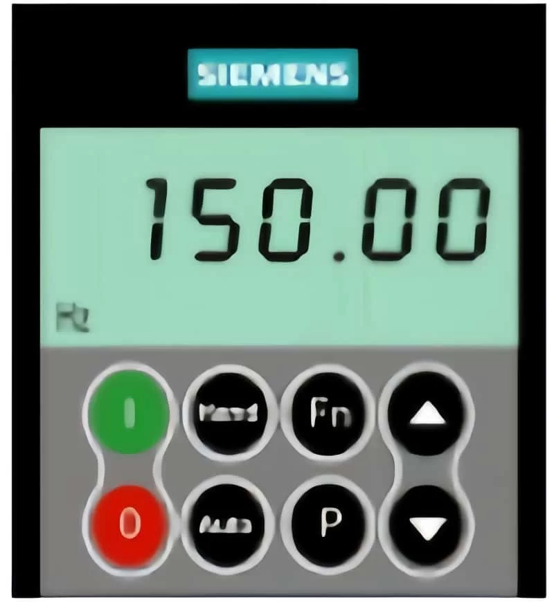
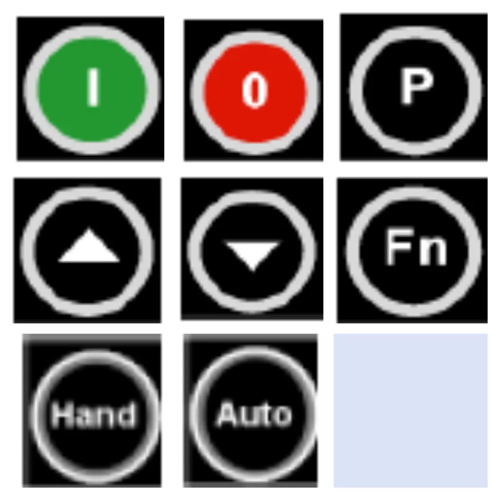
The operation panel of the Siemens VFD is equipped with several keys that serve different functions:
- Start/Stop Keys: Marked as 1 and 0, these control the run and stop operations.
- Parameter Adjustment Keys: The P key enters parameter adjustment mode, while the up and down arrows navigate through the parameters. The P key also confirms selections and writes values.
- Data Display/Reset Key: Press for 2 seconds to view operating data. It also serves as a return key after parameter adjustment and a reset button for fault shutdown.
- Control Mode Switch Keys: The “Hand” key enables operation via the panel, while the “Auto” key switches to terminal control.
Quick Start Guide for New Machines
For newly manufactured machines, you can bypass extensive parameter adjustments by understanding the basic button functions and ensuring correct terminal connections. However, for used machines, it’s often simplest to initialize all parameters to their factory settings:
- Set P0010=30
- Set P0970=1
After entering these values, the drive will reset, which may take about three minutes.
PID Operation Adjustment (440 Model)
For PID control, you’ll need to configure specific parameters:
- P2200=1: Enables PID function, disables conventional frequency settings.
- P2253: Selects the PID setting signal source (e.g., P2253=755 for analog input 1).
- P2264: Selects the PID feedback signal source.
Multi-machine operations, such as PID one variable frequency with three power frequencies, require detailed adjustments according to the manual.
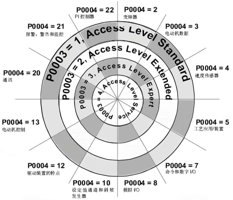
Tips for Parameter Adjustment
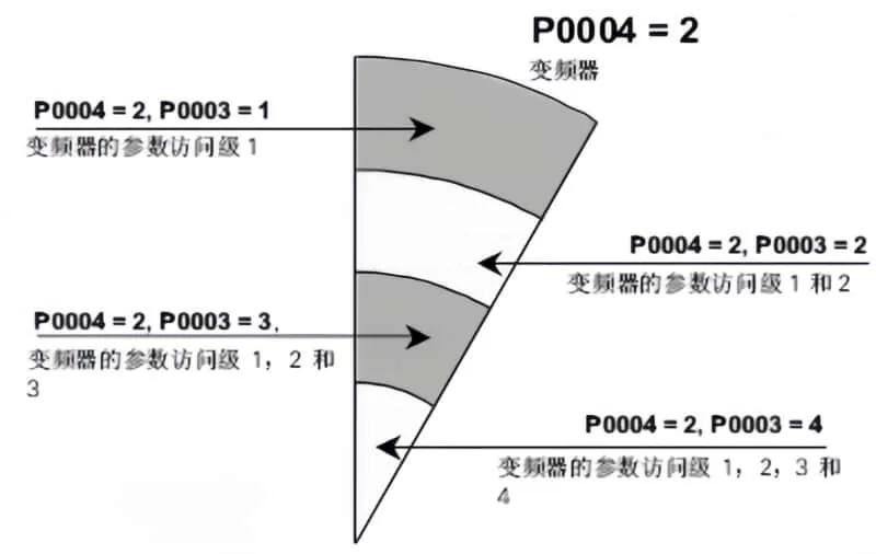
- To access PID parameters, set P003=3 for expert-level parameters.
- Adjust P004 to change specific parameter settings, such as P004=10 for frequency setting values.
- Define digital terminal functions with P700=2 for digital input control.
Shortcuts and Precautions
- Fault Reset: Set a terminal to 12 for reverse operation and fault reset.
- Fixed Frequency Operation: Set a terminal to 15 for multi-stage speed control. Adjust P1000=33 for analog signal plus fixed frequency.
- V/F Curve Adjustment: Customize the V/F curve with P1300 based on the load type (e.g., constant torque, variable torque).
Inertial (Free) Parking Control
For applications requiring inertial parking, set P701=1 for forward start/stop and P702=3 for inertial parking. Connect terminals 5 and 6 in parallel and control via terminal 9.
Special Considerations for High-Power Motors
When starting high-power motors, Siemens VFDs may output a certain excitation current to magnetize the stator winding before the motor starts. This is not a malfunction but a feature to reduce starting current.
Conclusion
By following this structured approach, even those new to Siemens 400 series VFDs can quickly become proficient in their operation and debugging. Remember to consult the manual for detailed parameter descriptions and always initialize parameters for used machines to ensure a smooth start. With a basic understanding of the operation panel, terminal connections, and key parameters, you’ll be well-equipped to handle a variety of applications and control requirements.