
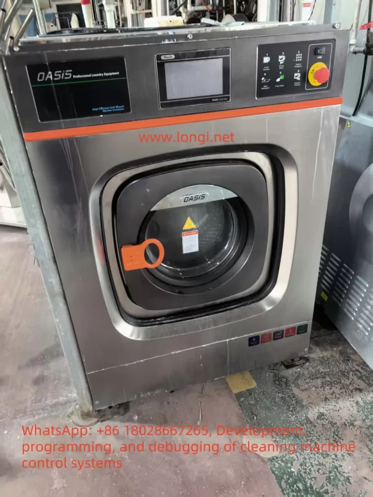
I. Functional Requirements Analysis of the Washing Machine
The washing machine is primarily used for efficient cleaning of various workpieces. Its core functional requirements include:
- Washing Pump Drive: A high-power motor is required to drive a high-pressure water pump for strong water jetting.
- Conveyor Belt Control: Drive the conveyor belt to achieve continuous workpiece transportation.
- Rotary Brush Control: Drive the rotary brush to perform mechanical scrubbing on the workpiece surface.
- Air-Drying System: Drive the fan to quickly dry the cleaned workpieces.
- Status Monitoring and Protection: Real-time monitoring of motor operation status is required, with overload, overvoltage, and other protection functions.
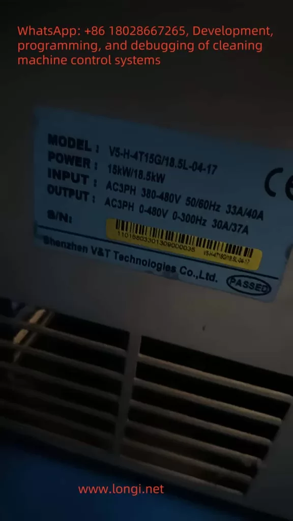
II. V5-H Inverter Selection and Configuration
Based on the power requirements of each functional module of the washing machine, the following V5-H inverter models are selected:
| Functional Module | Motor Type | Power Range | Inverter Model |
|---|---|---|---|
| Washing Pump | Three-phase asynchronous motor | 7.5-11kW | V5-H-11K |
| Conveyor Belt | Three-phase asynchronous motor | 1.5-2.2kW | V5-H-2.2K |
| Rotary Brush | Three-phase asynchronous motor | 2.2-3.7kW | V5-H-3.7K |
| Air-Drying System | Three-phase asynchronous motor | 1.5-2.2kW | V5-H-2.2K |
III. Control Circuit Design
1. Main Circuit Wiring
- Washing Pump Motor:
- Connect the inverter output terminals (U/T1, V/T2, W/T3) to the washing pump motor.
- Connect the braking unit DC output terminal (Ө) to the braking resistor (for rapid shutdown).
- Conveyor Belt Motor:
- Connect the inverter output terminals (U/T1, V/T2, W/T3) to the conveyor belt motor.
- Rotary Brush Motor:
- Connect the inverter output terminals (U/T1, V/T2, W/T3) to the rotary brush motor.
- Air-Drying System Motor:
- Connect the inverter output terminals (U/T1, V/T2, W/T3) to the fan motor.
2. Control Circuit Wiring
- Start/Stop Control:
- Connect the PLC output points to the inverter multi-function input terminals (X1-X7) to achieve remote start/stop.
- Speed Regulation:
- Connect the PLC analog output (0-10V) to the inverter analog input terminal (AI1) to achieve stepless speed regulation.
- Status Feedback:
- Connect the inverter multi-function output terminals (Y1, Y2/DO) to the PLC input points to feedback operation status.
- Fault Protection:
- Connect the inverter fault output terminal to the PLC input point to achieve fault alarming.
- Wiring Diagram:
- PLC output points (Q0.0-Q0.3) → Inverter multi-function input terminals (X1-X7)
- PLC analog output (AQ0.0) → Inverter analog input terminal (AI1)
- Inverter multi-function output terminals (Y1, Y2/DO) → PLC input points (I0.0-I0.1)
- Inverter fault output terminal → PLC input point (I0.2)
IV. Parameter Setting and Optimization
1. Basic Parameter Setting
| Parameter Group | Parameter Name | Setting Value/Range | Description |
|---|---|---|---|
| P0.03 | Control Mode Selection | 1 (Vector Control 1) | Suitable for heavy-duty applications such as washing pumps |
| P0.04 | Frequency Command Method | 1 (AI1 Voltage Command) | Regulate speed through PLC analog output |
| P0.05 | Maximum Operating Frequency | 50Hz | Set according to motor rated frequency |
| P0.08 | Acceleration Time | 5s | Adjust according to load characteristics |
| P0.09 | Deceleration Time | 5s | Adjust according to load characteristics |
2. Advanced Parameter Setting
| Parameter Group | Parameter Name | Setting Value/Range | Description |
|---|---|---|---|
| P8.00 | PID Control Selection | 1 (Enable PID) | Used for closed-loop control of temperature, pressure, etc. |
| P8.01 | Proportional Gain | 2.0 | Adjust according to system response |
| P8.02 | Integral Time | 10s | Adjust according to system stability |
| P8.03 | Derivative Time | 0.1s | Adjust according to system damping |
| P5.01 | Multi-function Input Terminal X1 | 15 (Forward Start) | Define terminal function |
| P5.02 | Multi-function Input Terminal X2 | 16 (Reverse Start) | Define terminal function |
| P7.01 | Multi-function Output Terminal Y1 | 32 (Running) | Define output status |
| P7.02 | Multi-function Output Terminal Y2 | 33 (Fault Output) | Define fault output |
3. Motor Parameter Auto-Tuning
- Set P9.15=1 to activate the motor parameter auto-tuning function.
- Input rated voltage, current, speed, and other parameters according to the motor nameplate.
- Optimize vector control performance after auto-tuning is complete.
V. Collaborative Control of PLC and Inverter
1. PLC Selection
- Model: Siemens S7-1200 CPU 1214C DC/DC/DC
- Features:
- 14 digital input points, 10 digital output points.
- 2 analog input channels, 1 analog output channel.
- Supports Modbus RTU communication protocol.
2. Control Program Logic
- Washing Pump Control:
- Regulate inverter output frequency through PID algorithm based on pressure sensor feedback.
- Achieve constant pressure water supply to improve washing efficiency.
- Conveyor Belt Control:
- Achieve precise positioning through pulse encoder feedback of position information.
- Automatically adjust conveyor belt speed according to workpiece size.
- Rotary Brush Control:
- Control rotary brush start/stop through a timer to achieve intermittent scrubbing.
- Adjust rotary brush speed according to workpiece material.
- Air-Drying System Control:
- Automatically adjust fan speed according to ambient temperature.
- Achieve energy-efficient operation.
- PLC Program Flowchart:
- Start → Initialization → Read Sensor Data → Execute PID Algorithm → Output Control Signal → Monitor Status → Fault Handling → End
VI. Human-Machine Interface Design
1. Touch Screen Selection
- Model: Kunlun Tongtai TPC7062KS
- Features:
- 7-inch TFT LCD display with a resolution of 800×480.
- Supports Modbus RTU communication protocol.
- Provides a rich library of graphics and controls.
2. Interface Design
- Main Interface:
- Display the washing machine’s operation status, motor speeds, temperature, pressure, and other parameters.
- Provide manual/automatic mode switching buttons.
- Parameter Setting Interface:
- Allow users to modify key parameters such as PID parameters, acceleration/deceleration time, and frequency limits.
- Provide parameter saving and restoration functions.
- Fault Alarm Interface:
- Display fault type, occurrence time, and handling methods.
- Provide fault confirmation and reset buttons.
- Touch Screen Interface Diagram:
- [Main Interface]
- Operation Status: Running
- Washing Pump Speed: 30Hz
- Conveyor Belt Speed: 0.5m/s
- Rotary Brush Speed: 15r/min
- Temperature: 40℃
- Pressure: 0.5MPa
- [Manual/Automatic Switching Button]
- [Parameter Setting Interface]
- PID Proportional Gain: 2.0
- PID Integral Time: 10s
- Acceleration Time: 5s
- Deceleration Time: 5s
- Frequency Limit: 50Hz
- [Save Parameters Button] [Restore Default Button]
- [Fault Alarm Interface]
- Fault Type: Overload Alarm
- Occurrence Time: 2025-04-06 10:00:00
- Handling Method: Check motor load, reduce operating frequency
- [Confirm Fault Button] [Reset Button]
- [Main Interface]
VII. System Integration and Debugging
1. System Integration
- Connect the PLC, inverter, and touch screen through the Modbus RTU bus.
- Configure communication addresses for each device to ensure efficient data exchange.
2. System Debugging
- No-Load Debugging:
- Check whether the rotation direction and speed of each motor are consistent with the design.
- Verify the stability and response speed of the PID control algorithm.
- Load Debugging:
- Test the system’s stability and reliability under different load conditions.
- Adjust parameters to optimize washing effect and energy-saving performance.
- Fault Simulation:
- Simulate faults such as overload and overvoltage to verify the reliability of protection functions.
- Test the real-time performance of fault alarming and reset functions.
VIII. Conclusion
This solution achieves efficient and stable operation of the washing machine through the vector control technology and rich I/O interfaces of the V5-H inverter. Combined with the collaborative control of the PLC and touch screen, it improves the system’s automation level and operational convenience. Through parameter auto-tuning and PID algorithm optimization, it further enhances the washing effect and energy-saving performance. This solution can be widely applied in the cleaning of automobile parts, industrial components, and other fields, with broad market prospects.