I. Introduction to Operation Panel Functions and Parameter Settings
Operation Panel Functions
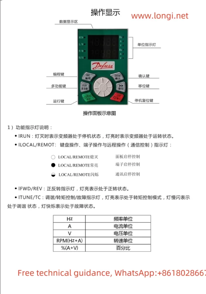
The Difuss Inverter DS9 series features an intuitive and user-friendly operation panel, which primarily comprises a data display area, function indicators, a numeric display area, and multiple function keys. The data display area shows the current operating status, set values, and monitoring data. Function indicators such as IRUN (Running Indicator) and ILOCAL/REMOTE (Operation Mode Indicator) help users quickly understand the inverter’s working status. The numeric display area, with a 5-digit LED display, supports the display of set frequency, output frequency, various monitoring data, and alarm codes. Function keys include PRG (Program Key), ENTER (Confirm Key), FUN (Multi-function Key), Shift Key, RUN (Run Key), and STOP/RES (Stop/Reset Key), facilitating parameter setting and operational control.

Parameter Settings
1. Setting Rated Frequency, Current, and Power
The DS9 inverter allows users to set the motor’s rated frequency, current, and power based on actual needs. These parameters are typically set in the P1 group of motor parameters. For instance, the motor’s rated power is set via P1-01, and its rated current is set via P1-03. Proper setting of these parameters is crucial for the normal operation of the inverter, ensuring that the motor operates stably within its rated working range.
2. Setting Upper and Lower Limit Frequencies
The upper and lower limit frequencies are set through parameters P0-12 and P0-14, respectively. The upper limit frequency defines the maximum frequency output by the inverter, while the lower limit frequency defines the minimum output frequency. Setting these parameters helps protect the motor from overload or damage during low-speed operation, ensuring stable operation within the set frequency range.
Application Macro Settings
CNC Machine Tool 100Hz Macro
By setting P0-29=11, you can select the CNC Machine Tool 100Hz macro. Tailored for CNC machine tool applications, this macro ensures stable inverter operation at 100Hz, meeting the high precision and stability requirements of CNC machine tools.
Spindle 400Hz Macro
By setting P0-29=21, 22, or 23, you can select different spindle 400Hz macros. Designed for high-speed spindle motors, these macros support output frequencies of up to 400Hz, catering to the needs of precision machining and high-speed cutting. Users can choose the appropriate macro based on specific application scenarios and fine-tune it through parameters like P0-03 and P0-08 to achieve optimal performance.

II. Terminal Control and External Speed Regulation Settings
Forward and Reverse Control
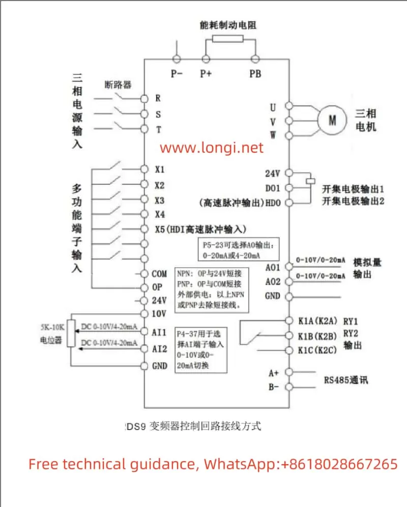
Achieving forward and reverse control of the inverter through terminals is straightforward. First, configure terminal X1 for forward operation (FWD) and terminal X2 for reverse operation (REV). The specific settings are as follows:
- Enter the P4 group of input terminal settings and set P4-00 to 1 (X1 terminal for forward operation).
- Set P4-01 to 2 (X2 terminal for reverse operation).
After these settings, controlling the on/off states of terminals X1 and X2 via external switches or PLCs enables forward and reverse control of the inverter.
External Potentiometer Speed Regulation
External potentiometer speed regulation is a commonly used speed control method that adjusts the inverter’s output frequency by changing the potentiometer’s resistance. The specific settings are as follows:
- Configure AI1 terminal as an analog input to receive voltage signals from an external potentiometer. Select the AI1 curve via parameter P4-33 and set parameters such as P4-13 to P4-16 to define the correspondence between input voltage and output frequency.
- During wiring, connect the sliding end of the external potentiometer to the AI1 terminal and its fixed ends to the +10V and GND terminals, respectively.
After completing the settings and wiring, rotating the potentiometer changes the inverter’s output frequency, enabling speed regulation.
III. Fault Code Analysis and Solutions
The DS9 inverter boasts a comprehensive fault protection mechanism that stops the inverter promptly and displays the corresponding fault code in case of a fault. Here are some common fault codes and their solutions:
- Err01 (Inverter Unit Protection): May be caused by output circuit short circuit, excessive length of motor and inverter wiring, or module overheating. Solutions include troubleshooting peripheral issues, installing reactors or output filters, and checking for blocked air ducts.
- Err02 (Acceleration Overcurrent): May result from too short an acceleration time, low voltage, or excessive load. Solutions include increasing the acceleration time, adjusting the voltage to the normal range, or reducing the load.
- Err03 (Deceleration Overcurrent): Similar to acceleration overcurrent, it may be caused by too short a deceleration time, low voltage, or excessive load. The solutions are also similar.
- Err14 (Module Overheating): May be due to high ambient temperature, blocked air ducts, or damaged fans. Solutions include lowering the ambient temperature, cleaning the air ducts, or replacing the fans.
When encountering a fault, users should first look up possible fault causes based on the displayed fault code and follow the corresponding solutions. If the problem persists, users should promptly contact the inverter manufacturer or agent for technical support.
IV. Conclusion
The Difuss Inverter DS9 Series Operation Manual provides users with a comprehensive user guide, covering operation panel function introduction, parameter setting methods, terminal control and external speed regulation settings, fault code analysis, and troubleshooting. By carefully reading and following the instructions in the manual, users can easily master the operation and maintenance skills of the inverter, ensuring stable and efficient equipment use.
