
I. Introduction to the Operation Panel Functions and Parameter Management
1.1 Introduction to the Operation Panel Functions
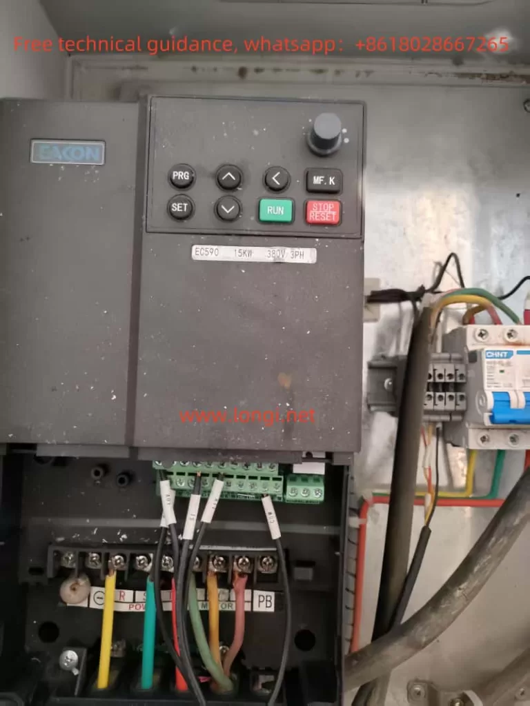
The operation panel of the EACON Inverter EC590 consists of LED digital displays, LEDs, and function buttons, capable of displaying the inverter’s operating status, frequency, current, voltage, and other parameters. The main buttons on the panel include RUN, STOP/RESET, PRG/SET, and MF.K (multi-function key). Through the operation panel, users can conveniently perform parameter settings, monitor operating status, reset faults, and other operations.
1.2 Copying Parameters to Another Inverter
To copy the parameters from one EACON Inverter EC590 to another, follow these steps:
- Ensure Identical Model Numbers: The premise for copying parameters is that both inverters must be of the same model to ensure parameter compatibility.
- Enter Parameter Copy Mode: On one inverter, press the PRG/SET button to enter the parameter setting mode, locate and set parameter FP-00 to a non-zero value (e.g., 1234) to enable the parameter copy function.
- Connect the Communication Cable: Use a dedicated communication cable to connect the communication interfaces of both inverters.
- Initiate the Copy Process: On the source inverter, press and hold the MF.K button for several seconds until the panel displays “COPY,” indicating that the copy process has started. At this time, the target inverter should be in standby mode.
- Complete the Copy: Once the copy process is complete, the source inverter’s panel will display “END,” indicating that the parameters have been successfully copied to the target inverter. At this point, the communication cable can be disconnected, and the FP-00 parameters of both inverters set to 0 to disable the parameter copy function.
1.3 Initializing Parameters
To initialize the parameters of the EACON Inverter EC590, follow these steps:
- Enter Parameter Setting Mode: Press the PRG/SET button to enter the parameter setting mode.
- Locate Initialization Parameter: In the parameter list, find parameter FP-01, which controls parameter initialization.
- Set Initialization Parameter: Set parameter FP-01 to 1 and press the MF.K button to confirm. At this point, the inverter will display “INIT,” indicating that the initialization process has started.
- Complete Initialization: After initialization is complete, the inverter will automatically restart. Upon restart, all parameters will be restored to their factory defaults.
1.4 Setting and Removing Passwords
Setting a Password
- Enter Parameter Setting Mode: Press the PRG/SET button to enter the parameter setting mode.
- Locate Password Setting Parameter: In the parameter list, find parameter FP-00, which is used to set the password.
- Set the Password: Set parameter FP-00 to the desired password value (e.g., 1234) and press the MF.K button to confirm. At this point, the password is set.
Removing a Password
- Enter Parameter Setting Mode: Press the PRG/SET button to enter the parameter setting mode.
- Locate Password Setting Parameter: In the parameter list, find parameter FP-00.
- Remove the Password: Set parameter FP-00 to 0 and press the MF.K button to confirm. At this point, the password is removed.
1.5 Setting Parameter Access Restrictions
The EACON Inverter EC590 provides a parameter access restriction function, which can be controlled by setting parameter FP-02 to control the display and modification permissions of different parameter groups.
- Enter Parameter Setting Mode: Press the PRG/SET button to enter the parameter setting mode.
- Locate Parameter Access Restriction Parameter: In the parameter list, find parameter FP-02.
- Set Access Restrictions: Set the value of parameter FP-02 as needed. For example, setting FP-02 to 10 (binary 1010) allows the display of U and A group parameters but prohibits modification.
II. External Terminal Control and Frequency Speed Regulation
2.1 External Terminal Control for Forward and Reverse Rotation
To achieve forward and reverse rotation control via external terminals, wiring and parameter settings are required as follows:
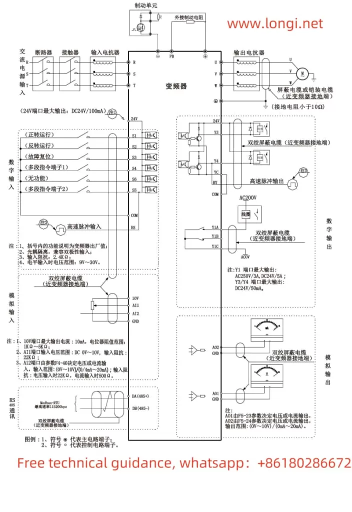
Wiring
- Forward Control: Connect the normally open contacts of an external switch or relay to the S1 and COM terminals of the inverter.
- Reverse Control: Connect the normally open contacts of an external switch or relay to the S2 and COM terminals of the inverter.
Setting Parameters
- Enter Parameter Setting Mode: Press the PRG/SET button to enter the parameter setting mode.
- Set Operation Command Source: Set parameter F0-02 to 1 (terminal control).
- Set Terminal Function: Set parameter F4-00 to 1 (S1 terminal for forward rotation) and parameter F4-01 to 2 (S2 terminal for reverse rotation).
2.2 External Potentiometer for Frequency Speed Regulation
To achieve frequency speed regulation via an external potentiometer, wiring and parameter settings are required as follows:
Wiring
- Potentiometer Wiring: Connect the three pins of an external potentiometer to the AI1, GND, and +10V terminals of the inverter. Among them, AI1 is the analog input terminal, GND is the grounding terminal, and +10V is the external power supply terminal.
Setting Parameters
- Enter Parameter Setting Mode: Press the PRG/SET button to enter the parameter setting mode.
- Set Frequency Command Source: Set parameter F0-03 to 4 (AI1 analog input).
- Set AI Curve: Set the input curve of AI1 as needed (e.g., parameters F4-13 to F4-16) to determine the relationship between analog input and frequency output.
III. Fault Codes and Solutions
The EACON Inverter EC590 provides a wealth of fault codes to indicate various faults during operation. The following are some common fault codes and their solutions:
3.1 Err02 (Acceleration Overcurrent)
Fault Meaning: Overcurrent occurs during acceleration of the inverter.
Solution:
- Check if the motor and load are too large.
- Increase the acceleration time (parameter F0-17).
- Check if the motor parameters are correctly set.
3.2 Err03 (Deceleration Overcurrent)
Fault Meaning: Overcurrent occurs during deceleration of the inverter.
Solution:
- Check if the motor and load are too large.
- Increase the deceleration time (parameter F0-18).
- Check if the braking unit and braking resistor are working normally.
3.3 Err04 (Constant Speed Overcurrent)
Fault Meaning: Overcurrent occurs during constant-speed operation of the inverter.
Solution:
- Check if the motor and load are too large.
- Check if the motor parameters are correctly set.
- Check for external interference sources.
3.4 Err11 (Motor Overload)
Fault Meaning: Motor overload.
Solution:
- Check if the motor and load are too large.
- Check if the motor parameters are correctly set.
- Increase the motor overload protection time (parameter F9-01).
3.5 Err15 (External Fault)
Fault Meaning: External fault input is active.
Solution:
- Check if there is a signal input at the external fault input terminal.
- Check if the external fault signal is normal.
- Reset the external fault input signal.
Through this operation guide, users can better understand and utilize the EACON Inverter EC590 to achieve efficient and stable motor control.