I. Introduction
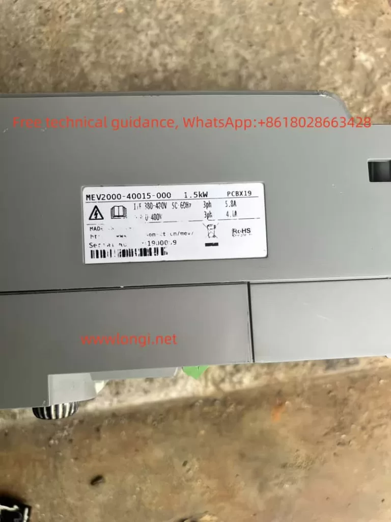
The Emerson Inverter MEV2000 series, with its high performance, high reliability, and wide range of applications, has become a preferred choice in the field of industrial control. This article will provide a detailed introduction to the panel functions, password setting and removal, parameter initialization methods of the MEV2000 series inverters. Additionally, it will explain how to use terminal control for forward and reverse starting and potentiometer speed adjustment. Finally, it will address the common Er.0234 fault, explaining its meaning and providing detailed solutions.

II. Inverter Panel Function Introduction
The operation panel of the Emerson Inverter MEV2000 series serves as the primary interface between the user and the device, featuring an LED display, function keys, and indicator lights. Users can utilize the panel to view inverter status, set operational parameters, and monitor input and output signals. The primary function keys on the panel include the program/exit key, function/data key, increase/decrease keys, and run/stop keys, which can be combined to perform various operations.
Password Setting and Removal
To protect the inverter parameters from unauthorized modification, the MEV2000 series inverters offer a password protection function. Users can set a password by configuring the FP.000 parameter. Once set, a password is required to modify parameters. If password protection needs to be removed, the following steps can be followed: first, unlock the user password using the correct password, then set the FP.001 parameter to 0, and finally reset the inverter to disable password protection.
Parameter Initialization
When users need to restore the inverter parameters to the factory settings, they can do so by configuring the FP.002 parameter. Setting FP.002 to 2 will clear all user-set parameters and restore them to the default factory settings. However, please note that this operation will not restore the motor parameters. To restore motor parameters, FP.002 should be set to 4.
III. Terminal Control for Forward and Reverse Starting and Potentiometer Speed Adjustment
Setting Parameters
To use terminal control for forward and reverse starting and potentiometer speed adjustment, the following parameters need to be configured:
- F0.000: Set the frequency given channel to digital given 1 (adjusted by the operation panel potentiometer).
- F0.004: Set the operation command channel to the terminal operation command channel.
- F7.008: Set the operation mode to two-wire operation mode 1 or 2, depending on the specific wiring method.
Wiring Terminals
- FWD: Forward control terminal, connected to an external forward start button or switch.
- REV: Reverse control terminal, connected to an external reverse start button or switch.
- +10V and 0V: Provide power to the potentiometer, connected to both ends of the speed adjustment potentiometer.
- AI1: Analog input terminal, connected to the sliding end of the speed adjustment potentiometer to receive the speed adjustment signal.

IV. Er.0234 Fault Meaning and Solution
Fault Meaning
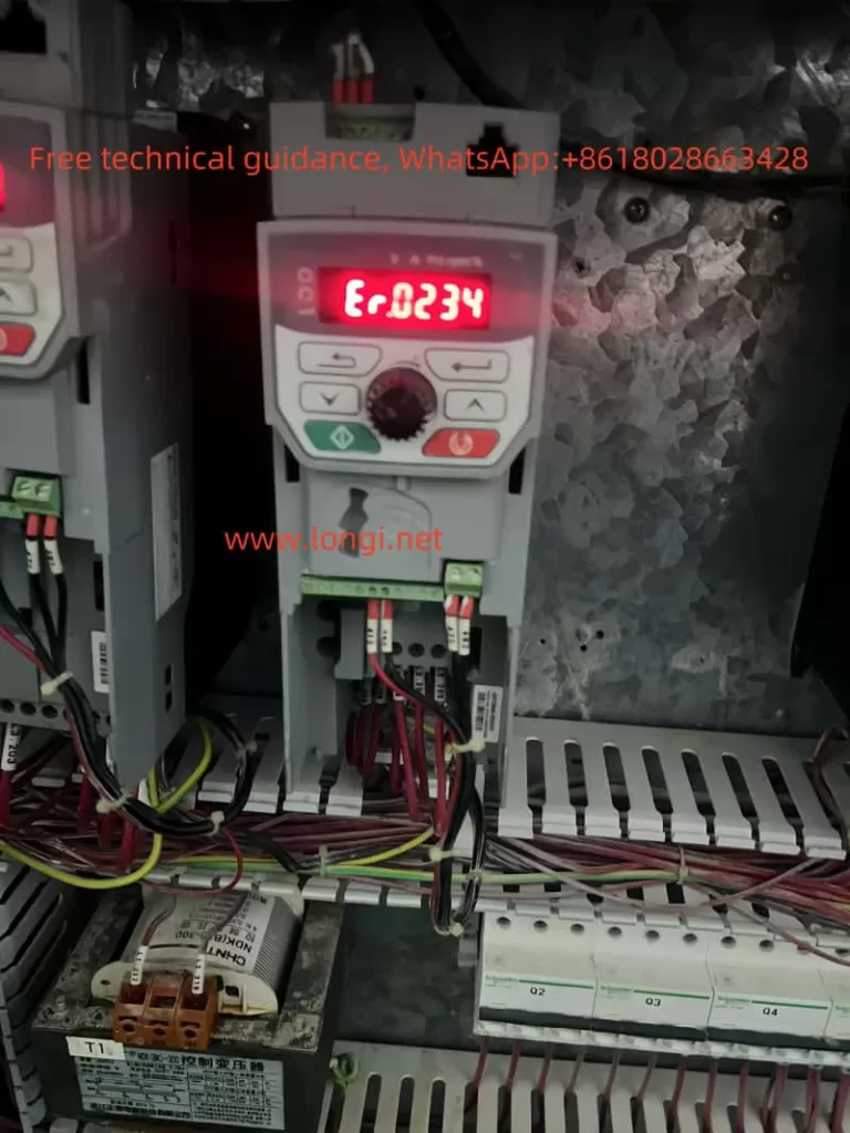
When the Emerson Inverter MEV2000 series displays the Er.0234 fault code, it indicates that either the OLX2 (overload relay board) or the STO (safety signal input board) is not installed or improperly connected. These two boards are crucial for the normal operation of the inverter, with the OLX2 responsible for monitoring overload conditions and the STO responsible for processing safety signals.
Solution
- Check Board Installation:
- First, confirm that the OLX2 board and STO board are correctly installed inside the inverter.
- Inspect the connections between the boards and the inverter’s mainboard to ensure they are secure and free from looseness or detachment.
- Check Wiring:
- Verify that the wiring for the OLX2 board and STO board is correct, with no misconnections or missing connections.
- Confirm that all connection wires are securely fastened and free from shorts or opens.
- Restart the Inverter:
- After confirming that the boards are installed and wired correctly, attempt to restart the inverter to see if the fault is resolved.
- If the fault persists, further inspection of the boards for potential damage may be necessary.
- Replace the Boards:
- If damage to the boards is confirmed, replace them with new OLX2 and STO boards promptly.
- After replacing the boards, reinstall and rewire them, then try to start the inverter again.
- Contact After-Sales Service:
- If the above steps fail to resolve the issue, it is recommended to contact Emerson Inverter’s after-sales service personnel for professional assistance.
V. Conclusion
The Emerson Inverter MEV2000 series plays a vital role in the field of industrial control due to its powerful functions and reliable performance. Through this article, users can gain a better understanding of the inverter’s panel functions, password setting and removal, parameter initialization methods, and how to use terminal control for forward and reverse starting and potentiometer speed adjustment. Additionally, for the common Er.0234 fault, this article provides detailed solutions to help users quickly locate and resolve the issue, ensuring the normal operation of the inverter.
