I. Introduction to Inverter Panel Functions
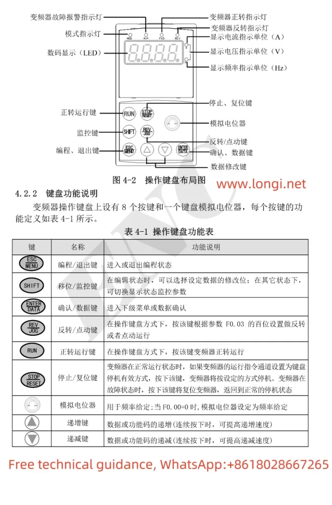
The ENC INVERTER EDS1000’s panel integrates various control functions, allowing users to easily start, stop, and adjust the speed of the inverter. The main keys on the panel include:

- RUN: Forward operation key. Pressing this key will start the inverter to run forward at the set frequency.
- STOP/RESET: Stop/Reset key. In normal operation, pressing this key will stop the inverter’s output; in fault mode, pressing this key will reset the inverter.
- REV JOG: Reverse/Jog key. Depending on the setting of parameter F0.03, this key can be used as a reverse operation key or a jog operation key.
- Analog Potentiometer: Used to manually adjust the inverter’s output frequency by rotating it, enabling speed control.
Steps to Achieve Panel Start/Stop and Speed Adjustment:
- Start the Inverter: Press the RUN key, and the inverter will start running at the currently set frequency and direction.
- Stop the Inverter: Press the STOP/RESET key, and the inverter will stop outputting.
- Speed Adjustment: Rotate the Analog Potentiometer on the panel to adjust the inverter’s output frequency in real-time, thereby achieving speed control.
II. Guide to Using the Simple PLC Function
The EDS1000 inverter provides a simple PLC function, allowing users to set different stages and corresponding times to automatically adjust the frequency and direction of the inverter within a cycle.
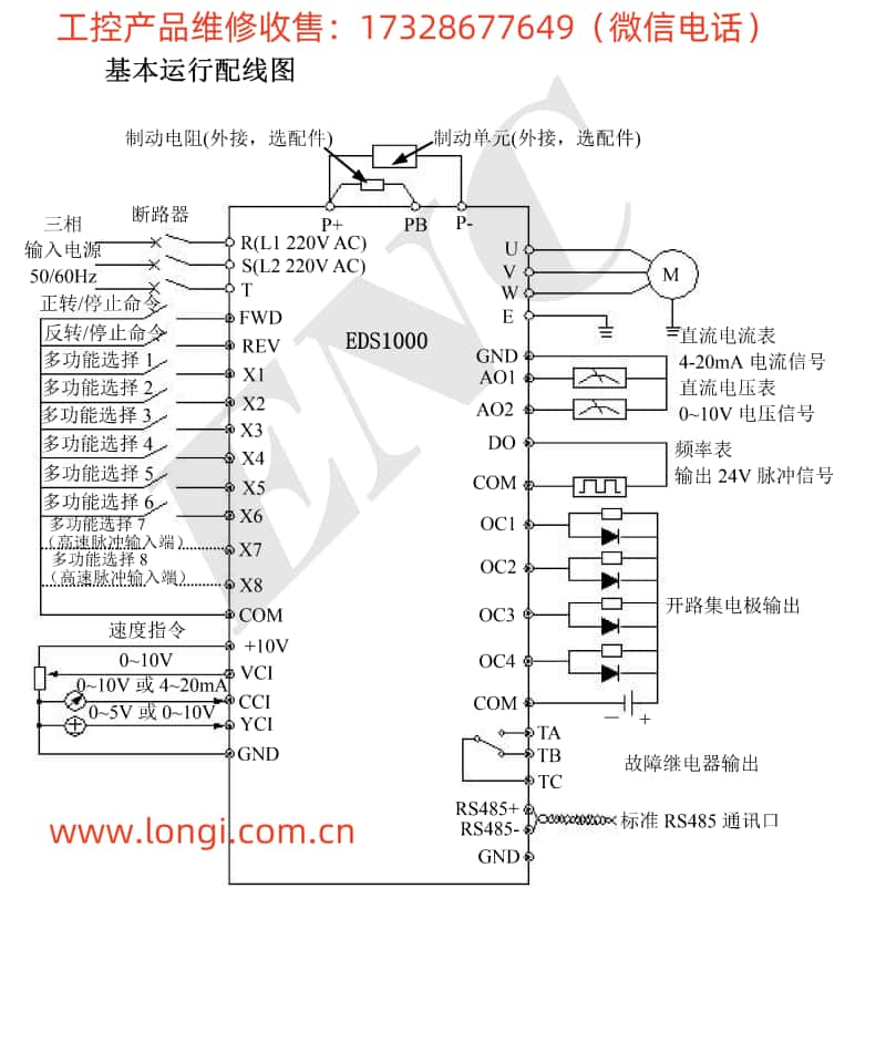
Terminal Connections:
- FWD: Forward control terminal.
- REV: Reverse control terminal.
- COM: Common terminal, used in conjunction with the FWD or REV terminal.
- X1-X8: Multifunctional input terminals, which can be used to set different stage controls.

Parameter Settings:
- F4.00: Simple PLC operation settings. Select the operation mode as needed (e.g., stop after a single cycle, continuous cycle, etc.).
- F4.01-F4.14: Set the frequency, direction, and operation time for each stage. For example, F4.01 sets the frequency and direction for the first stage, and F4.02 sets the operation time for the first stage.
Implementation Steps:
- Set the frequency, direction, and operation time for each stage through the F4 group parameters based on actual requirements.
- Connect the FWD and REV terminals to the corresponding control signals to control the forward and reverse rotation of the inverter.
- Connect the X1-X8 multifunctional input terminals as needed to trigger different stages.
- Start the inverter, and the simple PLC function will automatically adjust the inverter’s frequency and direction according to the set stages and times.
III. Setting the Swing Frequency Function
The swing frequency function is a special variable frequency operation mode that periodically varies the output frequency of the inverter within a certain range by setting parameters such as swing frequency amplitude and period.
Parameter Settings:
- F6.00: Swing frequency function selection. Set to 1 to enable the swing frequency function.
- F6.01: Swing frequency operation mode. Select the swing frequency input mode (automatic or manual) and amplitude type (variable amplitude or fixed amplitude).
- F6.02: Swing frequency amplitude. Set the amplitude of the swing frequency.
- F6.03: Jump frequency. Set the jump frequency at the start of swing frequency.
- F6.04: Swing frequency period. Set the time for one complete cycle of swing frequency.
Setting Steps:
- Set parameter F6.00 to 1 to enable the swing frequency function.
- Set parameter F6.01 as needed, selecting the swing frequency operation mode and amplitude type.
- Set parameter F6.02 to determine the amplitude of the swing frequency.
- Adjust the jump frequency and swing frequency period by setting parameters F6.03 and F6.04 as needed.
- Start the inverter, and the swing frequency function will operate according to the set parameters.
IV. Fault Codes and Handling Methods
The EDS1000 inverter provides extensive fault codes to help users quickly locate and resolve faults. Below are some common fault codes, their meanings, and handling methods:
- E001: Overcurrent during inverter acceleration. Possible causes include too short an acceleration time, an inappropriate V/F curve, etc. Handling methods include extending the acceleration time, adjusting the V/F curve, etc.
- E002: Overcurrent during inverter deceleration. Possible causes include too short a deceleration time, potential energy load or large inertia load, etc. Handling methods include extending the deceleration time, increasing external energy dissipation braking components, etc.
- E008: Inverter overload. Possible causes include too short an acceleration time, excessive DC braking, etc. Handling methods include extending the acceleration time, reducing the DC braking current, etc.
- E010: Inverter overheat. Possible causes include blocked air ducts, excessively high ambient temperature, etc. Handling methods include cleaning the air ducts, improving ventilation conditions, etc.
- E013: Inverter module protection. Possible causes include instantaneous overcurrent of the inverter, phase-to-phase or ground short circuit in the output three-phase, etc. Handling methods include checking and reconnecting wires, replacing damaged components, etc.
When the inverter encounters a fault, users should first check the possible causes based on the fault code and troubleshoot according to the provided handling methods. If the issue cannot be resolved, users should promptly contact the manufacturer or a professional technician for assistance.
Conclusion
The ENC INVERTER EDS1000 User Manual provides a detailed usage guide, covering panel function introductions, simple PLC function usage, swing frequency function settings, and fault code handling methods. By carefully reading the manual and following the guide, users can fully leverage the inverter’s capabilities to achieve efficient and stable variable frequency control.
