I. Overview of the Fault
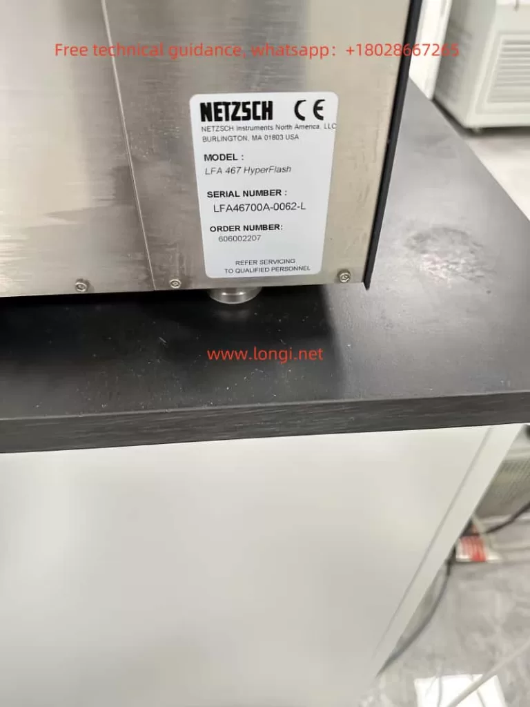
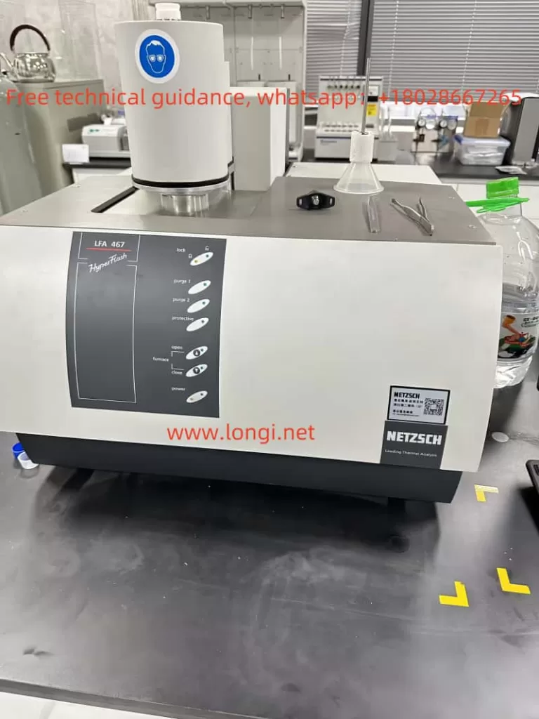
The NETZSCH LFA 467 Laser Flash Analyzer is an advanced thermal properties testing instrument used to measure the thermal diffusivity and conductivity of materials. The xenon flash lamp is one of its core components, responsible for providing high-energy thermal pulses to samples for precise measurement.
If the xenon flash lamp fails to light, it directly prevents the generation of the required energy pulses, thereby affecting the measurement results. Users must quickly identify and troubleshoot the root cause of the fault to restore normal operation of the instrument.
This article will analyze the causes and repair methods for the xenon flash lamp failure in the LFA 467, focusing on the fault implications, possible reasons, specific troubleshooting methods, and repair steps.
II. Implications and Possible Causes of the Fault
The failure of the xenon flash lamp to light indicates that the instrument has failed to complete the critical process of triggering and igniting the lamp. This issue may arise from the following factors:
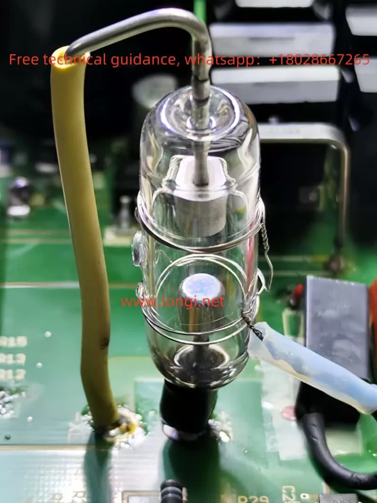
- Lamp Aging or Damage: The xenon lamp is a high-voltage gas discharge light source, where internal xenon gas is ionized by a high-voltage trigger electrode. When the gas leaks or electrodes age, the lamp cannot conduct or light properly.
- Trigger Circuit Failure: The xenon lamp requires a high-voltage pulse (thousands to tens of thousands of volts) provided by a pulse transformer. A failure in the pulse transformer, the thyristor in the trigger circuit, or the driving signal can lead to triggering issues.
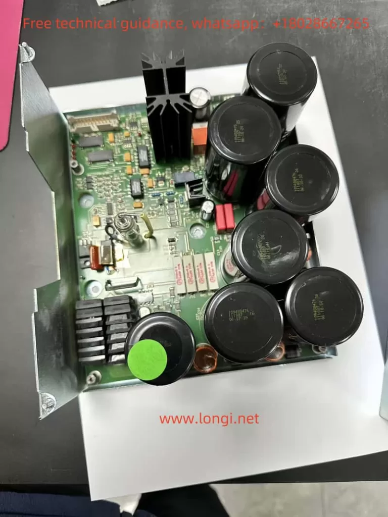
- Power Supply Circuit Anomalies: The xenon lamp’s anode and cathode require a stable DC high voltage (typically 300VDC). Faults in the rectifier bridge, storage electrolytic capacitors, or IGBT (Insulated Gate Bipolar Transistor) can prevent the lamp from receiving sufficient power.
- PWM Control Signal Issues: PWM (Pulse Width Modulation) signals regulate the power supply voltage to protect the lamp. Malfunctions in the driver circuit’s optocoupler, control chip (e.g., 74HC14D), or other components may result in excessive or insufficient lamp power.
- Insufficient Thermal Management: If key components (e.g., IGBT) overheat due to inadequate thermal dissipation, they may burn out, preventing the lamp from lighting.
III. Specific Troubleshooting Methods
The following steps can be taken to identify the fault source based on the above potential causes:
1. Test the Xenon Lamp
- Method: Use a multimeter to measure the resistance between the xenon lamp’s main electrodes. If the resistance is near short-circuit or open-circuit levels, the lamp is damaged.
- Alternative Test: Supply the lamp with approximately 300VDC externally while connecting a high-voltage trigger device (outputting 5kV-10kV) to the trigger electrode. If the lamp lights up, it is functional; otherwise, it should be replaced.
2. Check the Trigger Circuit
- Pulse Transformer: Measure the primary and secondary resistance of the pulse transformer with a multimeter. Ensure the primary resistance (~0.23 Ω) and secondary resistance (~230 Ω) match design values. Replace the transformer if values are abnormal or open.
- Thyristor: Measure the A-K and G-K resistance of the thyristor (e.g., TYN612MFP) to verify if leakage or a short-circuit exists. Replace the thyristor if anomalies are detected.
3. Check the Power Supply Circuit
- Electrolytic Capacitors: Use a capacitance meter to test the capacity of the storage capacitors. Replace them if the capacity drops significantly or leakage is observed.
- Rectifier Circuit: Inspect the rectifier bridge and related diodes for functionality. Use a multimeter to test forward and reverse resistance to confirm proper rectification.
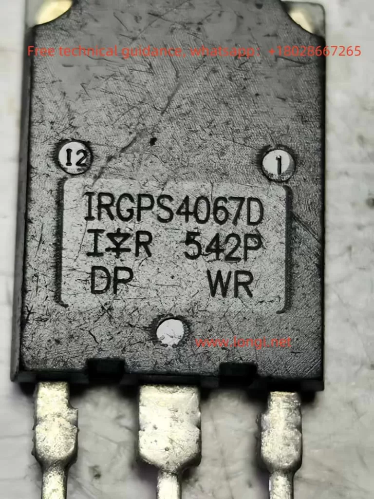
- IGBT Status: If the IGBT (e.g., IRGPS4067D) is damaged, power delivery to the lamp may be interrupted. Measure the C-E (collector-emitter) resistance with a multimeter to determine its condition. Burnt IGBTs should be replaced immediately.
4. Check the Driver and Control Circuit
- PWM Signal: Use an oscilloscope to examine the signal waveform of the optocoupler (e.g., AQY210LSX) and control chip (e.g., 74HC14D). Verify that the PWM duty cycle and frequency meet design requirements.
- Optocoupler Test: Test whether the optocoupler’s input and output terminals conduct properly using a multimeter or a simple test circuit.
5. Inspect Thermal Management
- Ensure the IGBT and thyristor’s heat sinks are properly attached, with evenly applied thermal paste.
- Clean dust around the heat sinks and verify that cooling fans are operating correctly.
IV. Repair Methods and Practical Steps
Step 1: Replace Damaged Components
Replace confirmed faulty components based on the troubleshooting results, including the xenon lamp, pulse transformer, thyristor, IGBT, electrolytic capacitors, etc.
Step 2: Strengthen Circuit Protection
- Add RC Snubber Circuit: Install an RC snubber network (e.g., 10 Ω + 0.1µF) across the IGBT and thyristor to absorb voltage spikes and protect critical components.
- Add TVS Diodes: Integrate TVS diodes into the high-voltage rectifier circuit to prevent transient voltage surges from damaging the circuit.
Step 3: Optimize PWM Driver Circuit
- Check and optimize the PWM signal’s duty cycle range to avoid excessively high or low output voltages.
- Ensure the stability of control signals to prevent false triggering due to interference.
Step 4: Test and Debug
- After replacing components, gradually power on the circuit to verify the functionality of the power supply.
- Test the trigger circuit to ensure the pulse transformer outputs a normal high voltage.
- Finally, connect and light the xenon lamp, observing its stable operation.
V. Conclusion and Recommendations
The xenon flash lamp in the NETZSCH LFA 467 Laser Flash Analyzer is a critical component, and its failure to light typically involves multiple circuit modules. Through systematic troubleshooting and repair, normal operation of the instrument can be quickly restored.
To prevent similar issues in the future, users are advised to perform regular maintenance on the circuit board, including cleaning heat sinks, inspecting critical components, and ensuring the instrument is not exposed to excessive voltage or current surges.
Scientific repair approaches and meticulous operations will help extend the instrument’s service life and ensure the accuracy of experimental results.
