I. Basic Operations and Parameter Settings of the Servo Unit
1. Factory Reset and Parameter Backup
- Factory Reset: To restore the servo unit to its default parameter settings, first enter the special password for modifying motor parameters, PA0=385. Then, find the corresponding code for your motor model (refer to Appendix A) and input it into parameter PA1. Finally, execute the parameter restoration operation.
- Parameter Backup: To prevent erroneous parameter modifications, you can back up the current parameters to the EEPROM backup area. Select the “Parameter Backup” option in the parameter management menu via the operation panel to complete the backup operation. To restore, select “Restore Backup”.
2. Setting the Motor Model Selection Parameter
- Motor Model Selection: Choose the compatible motor model by setting parameter PA1. After inputting the correct motor model code, the servo unit will automatically load the corresponding default parameters.
3. Jog Start and Stop
- Jog Operation: In the menu, select the jog operation mode (PA4=3), set the jog speed (PA21), and ensure PA98=1 to force internal enabling. Subsequently, control the motor’s start and stop for forward and reverse rotation using the “+” and “-” keys on the operation panel.
4. Parameter Optimization
- Speed Loop and Current Loop Optimization: The adjustments to the speed loop proportional gain (PA5) and integral coefficient (PA6) affect the servo system’s response speed and stability. The adjustments to the current loop filter coefficient (PA7) and speed feedback filter coefficient (PA8) influence the current smoothness and speed feedback response speed. These parameters need to be fine-tuned based on specific motor models and load conditions to achieve optimal performance.

II. Wiring and Parameter Settings Under Position Mode Control
1. Wiring Instructions
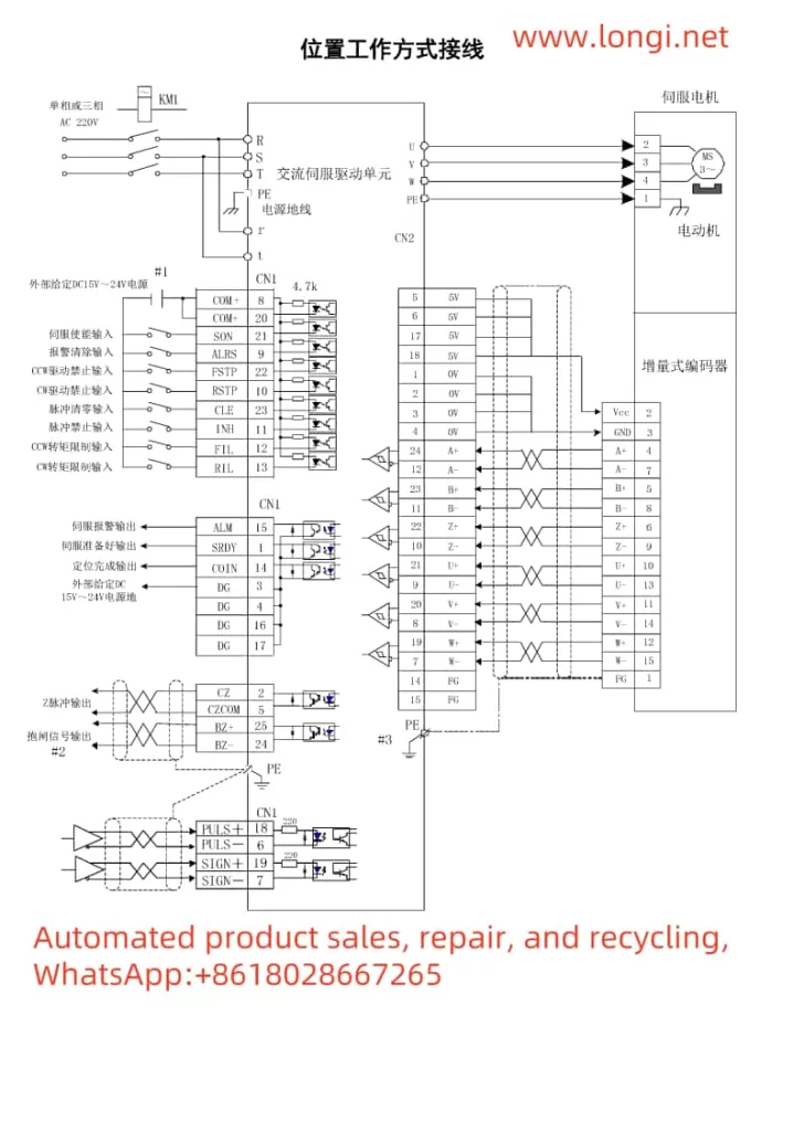
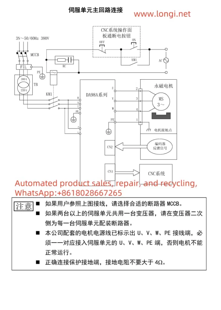
- Position Mode Wiring: The main connections include power input (R, S, T), motor output (U, V, W), control power (r, t), encoder feedback (CN2 interface), and control signals (CN1 interface). Refer to the wiring diagrams in the manual for specific terminal connections.
2. Forward and Reverse Control
- Forward and Reverse Implementation: Realize motor forward and reverse control by inputting pulse and direction signals through the PULS+, PULS-, and SIGN+, SIGN- terminals of the control signal CN1, or by using CCW and CW pulses. Set parameter PA14 to choose the pulse input mode (pulse + direction or CCW/CW pulses).
3. Key Parameter Settings
- Position Command Electronic Gear Ratio: Adjust the electronic gear ratio to match different pulse sources and control resolutions by setting parameters PA12 (pulse command multiplication coefficient) and PA13 (pulse command division coefficient).
- Position Command Pulse Input Mode: Set parameter PA14 to 0 for pulse + direction mode or to 1 for CCW/CW pulse mode.
- Position Arrival Signal: Set the position arrival range pulse number by adjusting parameter PA16. When the remaining pulse number in the position deviation counter is less than or equal to this value, the COIN signal outputs ON.

III. Fault Codes and Solutions
1. List of Fault Codes and Their Meanings
- Err-1: Overspeed, indicating that the servo motor speed exceeds the set value.
- Err-2: Overvoltage in the main circuit, indicating that the main circuit power supply voltage is too high.
- Err-3: Undervoltage in the main circuit, indicating that the main circuit power supply voltage is too low.
- Err-4: Position error, indicating that the value in the position deviation counter exceeds the set value.
- Err-9: Encoder fault, indicating that the encoder signal is erroneous.
- Err-11: IPM module fault, indicating that the IPM intelligent module is faulty.
- Err-12: Overcurrent, indicating that the motor current is too high.
- Err-13: Overload, indicating that the servo unit and motor are overloaded.
2. Solutions
- Err-1: Check the control circuit board, motor encoder, input pulse frequency, and electronic gear ratio settings, or adjust the load moment of inertia ratio.
- Err-2: Check the power supply, braking resistor wiring, internal braking resistor or circuit, or reduce the start-stop frequency and load inertia.
- Err-3: Confirm the main circuit power wiring, power supply voltage, power capacity, and heat sink status.
- Err-4: Check the pulse command frequency, electronic gear ratio settings, load inertia, motor encoder and its connections, or adjust the speed loop and position loop gains.
- Err-9: Inspect the encoder connector and signal wire soldering, shorten the encoder cable length, or replace the motor encoder.
- Err-11: Replace the servo unit, check the braking resistor wiring, adjust the current loop parameters, or reduce the load inertia.
- Err-12: Reduce the load, check the grounding, or replace the motor.
- Err-13: Adjust the speed loop gain, increase the acceleration/deceleration time, reduce the load inertia, or replace the high-power servo unit and motor.
IV. Scientific Usage Process of the Servo System
- System Installation and Wiring: Install the servo unit and motor correctly according to the installation instructions and wiring diagrams in the manual, ensuring all connections are accurate and error-free.
- Parameter Setting and Debugging: Set the corresponding parameters based on the motor model in use and conduct necessary debugging, including the optimization of key parameters such as the speed loop and current loop.
- Functional Testing: Conduct manual, jog, speed mode, and position mode operation tests under no-load conditions to ensure the servo system functions normally.
- Load Operation: After confirming the normal operation of the servo system under no-load conditions, connect the load for loaded operation testing and monitor the motor’s operating status and performance indicators.
- Fault Handling and Maintenance: In case of alarms or faults during use, troubleshoot and resolve them according to the fault codes and handling methods in the manual. Meanwhile, regularly maintain and service the servo unit and motor to ensure their long-term stable operation.
By following the above steps, you can ensure the scientific use and maintenance of the Guangzhou Numerical Control (GSK CNC) Servo Unit DA98A, improving production efficiency and equipment reliability.
