
I. Introduction to VFD Operation Panel Functions
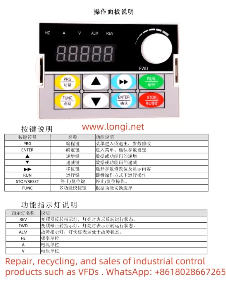
The HARS VFD HS710 series features a comprehensive and user-friendly operation panel. The panel primarily includes the following keys and indicators:
- PRG Programming Key: Used to enter or exit the menu for parameter modifications.
- ENTER Confirmation Key: Confirms parameter settings or enters the menu.
- ▲ Increment Key and ▼ Decrement Key: Used to increment or decrement data or function codes.
- Shift Key: Selects the parameter modification bit and display content.
- RUN Operation Key: Starts the VFD in keyboard operation mode.
- STOP/RESET Stop/Reset Key: Stops VFD operation or resets faults.
- FUNC Multi-function Quick Key: Switches functions according to needs.
Setting Passwords and Restoring Factory Defaults
- Setting Passwords:
- Enter the parameter setting interface (press the PRG key).
- Use the increment and decrement keys to select FE.29 (User Password) and press the ENTER key to enter.
- Use the numeric keys to enter the password value (0–65535) and press the ENTER key to confirm. The password setting will take effect after a 3-minute delay.
- Restoring Factory Defaults:
- Enter the parameter setting interface.
- Select F7.12 (Parameter Initialization) and press the ENTER key to enter.
- Use the increment key to select “2: Restore all user parameters to factory settings” and press the ENTER key to confirm. After the operation is complete, the parameters will automatically be restored to their factory default values, and F7.12 will automatically reset to 0.
II. Terminal Start/Stop and External Potentiometer Speed Regulation Wiring
Wiring Steps
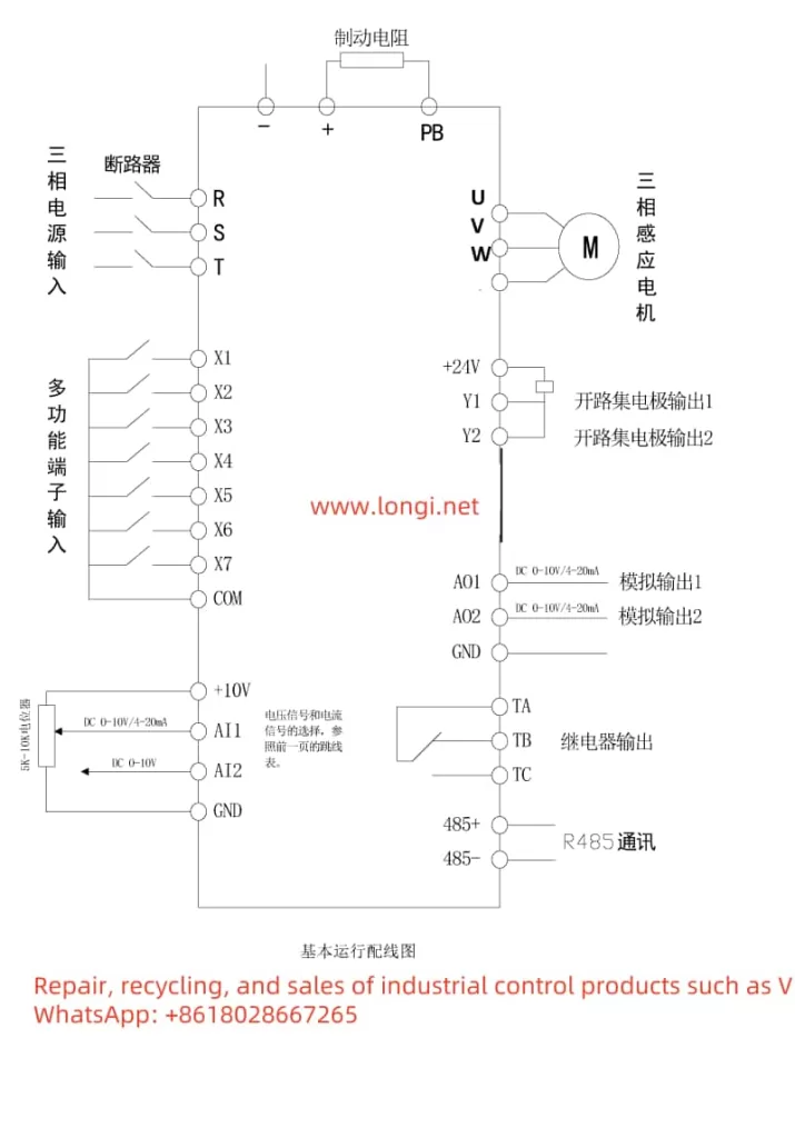
- Power Wiring:
- Connect the three-phase power supply to the R, S, T terminals of the VFD, ensuring the power supply matches the VFD.
- Install an air circuit breaker (NPB) between the power supply and input terminals to protect the circuit.
- Motor Wiring:
- Connect the U, V, W terminals of the motor to the corresponding U, V, W terminals of the VFD.
- Ensure the motor is properly grounded by connecting the E terminal of the VFD to the motor housing.
- Start/Stop Wiring:
- Connect the positive power supply (+24V) of the control circuit to the +24V terminal of the VFD.
- Connect one end of the external start button to the +24V terminal and the other end to the X1 terminal (Forward Operation).
- Connect one end of the external stop button to the COM terminal and the other end to the X1 terminal (Forward Operation) or another stop function terminal as configured.
- External Potentiometer Speed Regulation Wiring:
- Connect the center tap of the external potentiometer to the GND terminal of the VFD.
- Connect one end of the potentiometer to the +10V terminal.
- Connect the other end of the potentiometer to the AI1 terminal (Analog Input 1) to receive the speed control signal.
Parameter Settings
- Operation Command Channel Selection:
- Enter the parameter setting interface.
- Select F0.02 (Operation Command Channel Selection) and set it to “1: Terminal Operation Command Channel”.
- Analog Input Settings:
- Select F4.13 (AI1 Input Lower Limit) and F4.15 (AI1 Input Upper Limit) and set appropriate values according to the output range of the potentiometer.
- Select F4.14 (AI1 Lower Limit Corresponding Physical Quantity Setting) and F4.16 (AI1 Upper Limit Corresponding Physical Quantity Setting) and set them to “Speed Command” so that the potentiometer can control the output frequency.
- Frequency Source Selection:
- Select F0.03 (Main Frequency Source A Selection) and set it to “2: AI1 Analog Given”.
III. Fault Code Analysis and Troubleshooting
The HARS VFD HS710 series may display various fault codes during operation. Below is an analysis and troubleshooting guide for some common fault codes:
- E-01: Overcurrent During Acceleration
- Possible Causes: Too short acceleration time, overloaded load, improperly set V/F curve.
- Solutions: Extend the acceleration time, check for abnormal loads, adjust the V/F curve.
- E-02: Overcurrent During Deceleration
- Possible Causes: Too short deceleration time, excessive load inertia.
- Solutions: Extend the deceleration time, connect an external braking resistor or braking unit.
- E-08: Motor Overload
- Possible Causes: Improperly set V/F curve or torque boost, low grid voltage, overloaded load.
- Solutions: Adjust the V/F curve and torque boost, check the grid voltage, reduce the load, or select a VFD with a higher power rating.
- E-12: Input Phase Loss
- Possible Cause: Missing phase in the power input.
- Solution: Check the power supply and wiring to ensure a normal three-phase power supply.
- E-13: Output Phase Loss or Current Imbalance
- Possible Cause: Missing phase in output U, V, W.
- Solution: Check the output wiring to ensure correct motor connections.
By carefully reading the user manual and following the above guide, users can effectively operate and maintain the HARS VFD HS710 series, ensuring the normal operation of the equipment and extending its service life.