I. Introduction to Operation Panel Functions and Parameter Settings

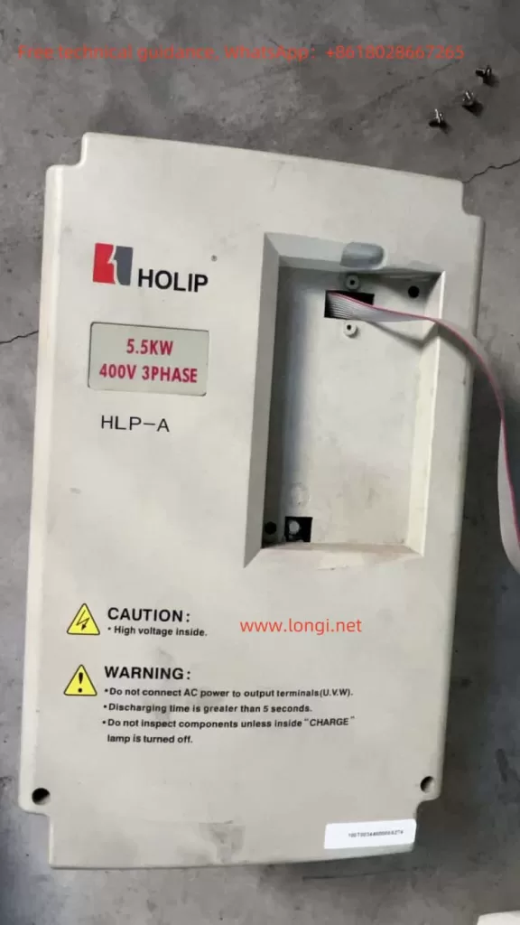
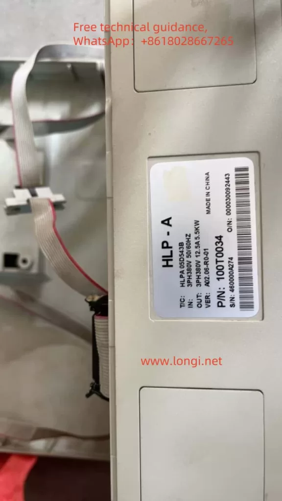
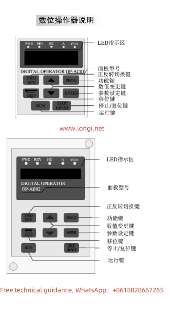
The HOLIP Inverter HLP-A series boasts a comprehensive operation panel that allows users to perform parameter settings, monitor operating status, and diagnose faults. The operation panel primarily includes a display screen, directional keys, set keys, run keys, stop keys, and other functional keys.
Setting and Resetting Passwords
To protect against unauthorized modification of inverter parameters, the HLP-A series supports password protection. Users can enable password protection by setting parameter CD010 to 1, at which point all parameters except CD010 become unmodifiable. To reset the password, simply set CD010 back to 0.
Locking Parameters
To prevent non-maintenance personnel from accidentally modifying parameters, users can lock all parameters except CD010 by setting CD010 to 1. Once locked, only the correct password (set through parameter CD011) can unlock the parameters for modification.

Initializing Parameters
When it is necessary to restore the inverter to its factory settings, users can set parameter CD011 to 08 and then press the run and stop keys simultaneously. The inverter will automatically restart and revert to its factory settings.
II. Terminal Forward/Reverse Control and External Potentiometer Frequency Adjustment
Terminal Forward/Reverse Control

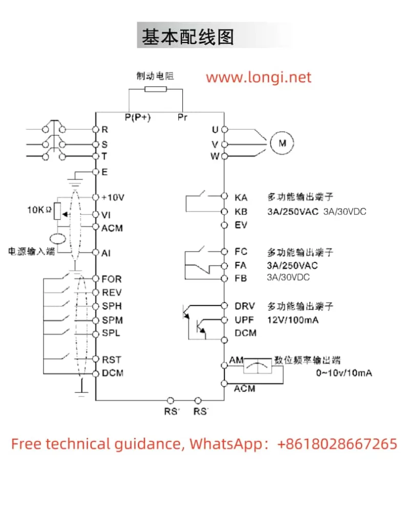
The HLP-A series inverter supports forward/reverse control via external terminals. Users need to set the multi-function input terminal FOR to forward (parameter CD050=02) and REV to reverse (parameter CD051=03). Then, by controlling the on/off state of these terminals with external switches, motor forward/reverse control can be achieved.
External Potentiometer Frequency Adjustment
External potentiometer speed control is a commonly used method for variable frequency speed control. Users need to set the inverter’s operation command source to external terminals (parameter CD033=1) and the operation frequency source to external analog (parameter CD034=1). Connect the potentiometer’s center tap to the VI terminal and its ends to the +10V and ACM terminals, respectively. By adjusting the potentiometer’s resistance, the inverter’s output frequency can be changed, thereby achieving motor speed control.

III. Fault Codes and Solutions
The HLP-A series inverter features comprehensive fault protection functions. When a fault occurs, the inverter will display the corresponding fault code. Below are some common fault codes, their meanings, and solutions:
E.OC.A (Overcurrent During Acceleration)
Meaning: The inverter experiences overcurrent during acceleration.
Solution: Check for short circuits or partial short circuits in the motor, and ensure good insulation of output wires; extend the acceleration time; check the inverter configuration for reasonableness and increase the inverter capacity if necessary; reduce the torque boost setting.
E.GF.S (Ground Fault)
Meaning: The inverter output is short-circuited to ground.
Solution: Check for short circuits in motor connections and ensure good insulation of output wires; if the fault cannot be resolved, contact the manufacturer for repair.
E.OU.S (Overvoltage During Stopping)
Meaning: The inverter experiences overvoltage during stopping.
Solution: Extend the deceleration time or install a braking resistor; improve the grid voltage quality and check for sudden voltage fluctuations.
E.OL.A (Inverter Overload)
Meaning: The inverter is overloaded.
Solution: Check if the inverter capacity is too small and increase it if necessary; check for stuck mechanical loads; reset the V/F curve.
E.OT.A (Motor Overtorque)
Meaning: The motor experiences overtorque.
Solution: Check for fluctuations in mechanical loads; check if the motor configuration is too small; check for deterioration in motor insulation due to overheating; check for significant voltage fluctuations; check for phase loss; check for increased mechanical loads.
IV. Conclusion
The HOLIP Inverter HLP-A series user manual provides users with detailed operation guides and fault solutions. By understanding the operation panel functions, mastering terminal control and potentiometer speed adjustment methods, and being familiar with fault code meanings and solutions, users can better utilize and maintain the inverter, ensuring its stable operation and extended service life. In practical applications, users should strictly follow the instructions in the manual for operation and maintenance to ensure the performance and safety of the inverter.
