
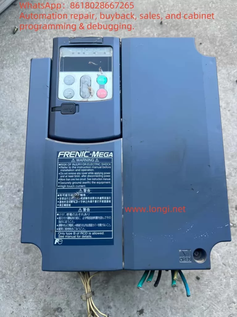
As a key device in the field of industrial control, Fuji Inverter G1S series indicates fault states through different forms of horizontal lines on its operation panel. Based on extensive field cases and technical data, this article provides a comprehensive analysis of horizontal line faults (including the middle horizontal line “—-” and the upper and lower horizontal lines) and offers actionable diagnostic procedures and solutions.
I. Fault Patterns and Core Implications
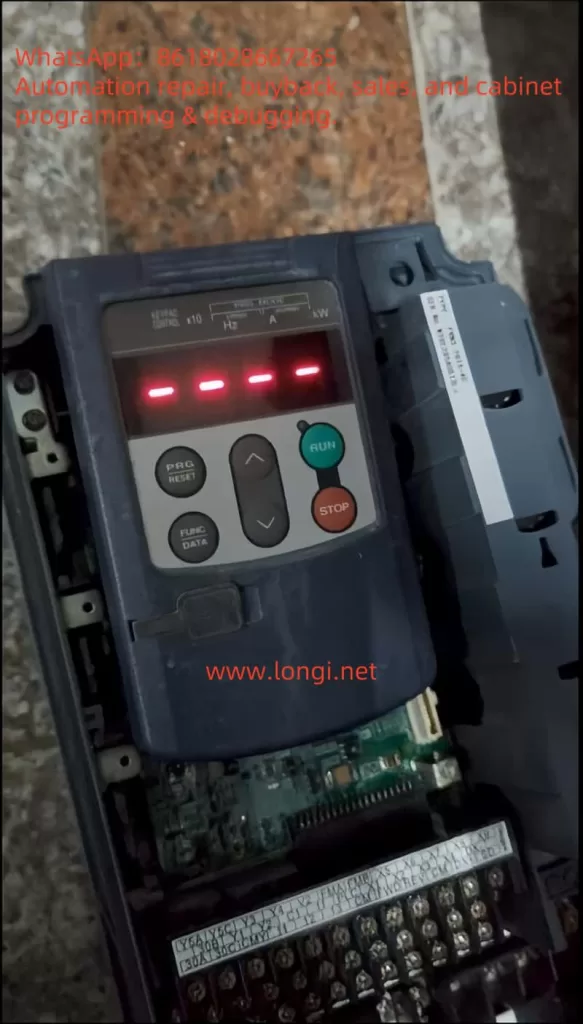
1. Middle Horizontal Line “—-” Fault
Display Feature: The LED monitor displays four consecutive horizontal lines.
Core Implication:
- PID Control Conflict: When J01=0 (PID control is not enabled), if the E43 parameter is forcibly set to display PID parameters, the system will return invalid data.
- Communication Link Anomaly: Poor connection between the operation panel and the inverter body, such as damage to the shield layer of the extension cable or oxidation of the cable.
2. Lower Horizontal Line “_ _ _ _” Fault
Display Feature: The motor stops after the command is triggered, and the panel displays an underscore.
Core Implication:
- Insufficient DC Bus Voltage: The measured voltage is below DC400V (for 400V models), often caused by non-compliant input power specifications or excessive line voltage drop.
- Missing Main Power Supply: The control power is on, but the main power circuit breaker is not closed.
- Power Configuration Conflict: When H72=1, an abnormal main power supply is detected, such as DC power supply incorrectly connected to the AC input terminal.
II. Standardized Diagnostic Procedures
Step 1: Quick Status Confirmation
- Power Supply Check:
- Main Power Supply: Measure the voltage between L1-L2-L3 to confirm compliance with the inverter specifications (e.g., 400V ±10%).
- Control Power Supply: Check the stability of the 24V auxiliary power supply to avoid OC3 alarms caused by fan shorts.
- Panel Operation Verification:
- Perform a reset operation (long press the RST key) to observe if the fault can be cleared.
- Read the communication error counter through parameter viewing mode (e.g., d001-d005).
Step 2: Layered Fault Location
| Fault Layer | Inspection Item | Technical Details |
|---|---|---|
| Communication Layer | Extension Cable | Use a megohmmeter to measure the cable insulation resistance >10MΩ and check the continuity of the shield layer. |
| Power Layer | DC Bus | Measure the P(+)-N(-) voltage during startup and compare it with the value displayed on the operation panel (error should be <5%). |
| Control Layer | Parameter Configuration | Focus on checking critical parameters such as J01 (PID control) and H72 (main power detection). |
Step 3: In-Depth Hardware Inspection
- Main Circuit Check:
- Disconnect the main power supply and measure the resistance of the rectifier bridge and IGBT module to check for short circuits.
- Check the connection status of the braking resistor to avoid OU1/OU2 overvoltage alarms.
- Control Board Check:
- Use an oscilloscope to monitor the PWM output waveform of the mainboard to confirm the integrity of the drive signal.
- Perform a “hot swap” test on suspected faulty boards to locate the specific damaged component.
III. Practical Cases of Typical Faults
Case 1: Lower Horizontal Line Fault in a Plastic Extruder
Fault Phenomenon: The motor does not respond after the start command, and the panel displays a lower horizontal line.
Diagnostic Process:
- Measure the main power supply voltage at 380V (standard 400V), confirming excessive voltage drop.
- Check the DC bus voltage at 360V (standard ≥400V), locating insufficient voltage.
- Find an incorrect transformer tap setting, resulting in low input voltage.
Solution:
- Adjust the transformer tap setting to the 400V output position.
- Install an APFC device to improve power quality.
Case 2: Middle Horizontal Line Fault in a CNC Machine
Fault Phenomenon: The panel displays “—-” after parameter modification.
Diagnostic Process:
- Find that E43 is mistakenly set to PID feedback value, while J01=0.
- Check the panel extension cable and find that the shield layer is worn at the cable tray.
Solution:
- Change E43 to frequency display mode.
- Replace the shield cable and optimize the cable routing path.
IV. Preventive Maintenance Strategies
- Periodic Inspection Plan:
- Daily: Visually inspect the panel display status and record the operating environment temperature and humidity.
- Monthly: Measure the main power supply voltage, DC bus voltage, and calibrate PID control parameters.
- Quarterly: Perform a main power supply power-off restart test and check the contacto r suction status.
- Spare Parts Management Optimization:
- Establish a lifespan model for critical spare parts (e.g., IGBT modules, DC capacitors).
- Sign an emergency supply agreement with suppliers to ensure a 48-hour response.
- Technology Upgrade Path:
- Regularly upgrade firmware versions to utilize new algorithms for optimizing fault detection mechanisms.
- Consider an overall upgrade to the G1S-P series for aging equipment (>5 years).
V. Technical Development Trends
With the development of industrial IoT technology, Fuji Inverter G1S series now supports remote monitoring and predictive maintenance functions. By integrating edge computing nodes, the following can be achieved:
- Real-time Fault Feature Extraction: Utilize AI algorithms to analyze waveform data and identify potential faults in advance.
- Cloud Expert Diagnosis: Upload fault data to the cloud platform for expert system solutions.
- Digital Twin Applications: Build a virtual model of the equipment to simulate fault scenarios and practice response drills.
Conclusion
Handling horizontal line faults in Fuji Inverter G1S series requires engineers to possess a solid knowledge of power electronics and a systematic diagnostic mindset. The standardized procedures and practical cases provided in this article enable users to quickly locate more than 80% of common faults. For complex issues, it is recommended to combine official technical documentation and dedicated diagnostic tools for in-depth analysis. Continuous technical training and knowledge updating are the keys to improving fault handling efficiency.