
Introduction
In the field of industrial automation, ABB’s ACS580 series inverter is widely used in various drive control scenarios due to its high efficiency and stable performance. However, during actual operation, the inverter may encounter faults for various reasons, among which FAULT 7086 is a relatively typical issue. This article will systematically analyze the handling strategies for this fault from the aspects of fault definition, causes, solutions, and preventive measures, providing comprehensive guidance for equipment maintenance personnel.
I. Fault Definition and Background Analysis
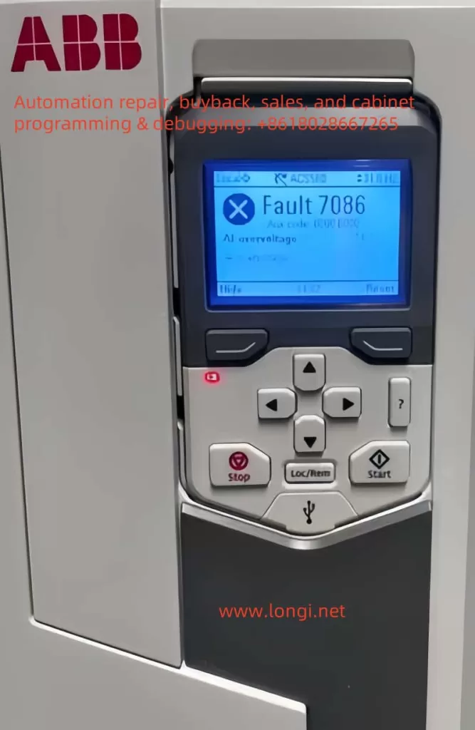
FAULT 7086 is officially defined as Analog Input Overvoltage (AI Overvoltage), which means the inverter detects that the voltage of the analog input (AI) signal exceeds the preset threshold. When this fault is triggered, the inverter will automatically switch the AI input mode from current mode to voltage mode to protect the circuit. After the signal returns to normal, the system can switch back manually or automatically.
From a design logic perspective, the AI input is a crucial interface for the inverter to receive external control signals (such as sensor data and setpoints). Its stability directly affects the control accuracy and system safety. When the input voltage rises abnormally, it may damage the internal circuit or cause control logic errors. Therefore, the inverter needs to issue an early warning through a fault code.
II. In-depth Analysis of Fault Causes
2.1 AI Signal Source Issues
- Sensor Failure: Sensors for temperature, pressure, etc., may output abnormally high voltages due to aging or damage.
- Signal Source Configuration Errors: For example, connecting a 0-10V output device to a 4-20mA input terminal, resulting in signal level mismatch.
2.2 Wiring and Interference Issues
- Short Circuit in Wiring: Short circuits in AI signal lines or damage to connectors.
- Electromagnetic Interference (EMI): Parallel routing of AI signal lines with high-power lines (such as motor cables and inverter output lines) without shielding measures.
2.3 External Device Failures
- PLC or Controller Anomalies: Control devices may output error signals due to program errors or hardware failures.
- Power Fluctuations: Unstable power supply to external devices, leading to signal level fluctuations.
2.4 Drive Internal Failures
- AI Processing Circuit Damage: Aging components, lightning strikes, or operational errors causing circuit failure.
- Firmware Version Defects: Old firmware versions may have vulnerabilities in AI input detection algorithms.
III. Fault Impact and Risk Assessment
3.1 Direct Impact on the Control System
- Reduced Control Accuracy: AI input anomalies may cause deviations in setpoints such as speed and torque.
- System Shutdown: If the fault is not cleared in time, the inverter may trigger protective shutdown.
3.2 Potential Risk Analysis
- Equipment Damage: Prolonged overvoltage may burn out the AI input module or main control board.
- Production Loss: Sudden shutdowns or control anomalies may halt production lines, resulting in economic losses.
IV. Systematic Solutions
4.1 Preliminary Diagnostic Process
- Observe the Control Panel: Confirm whether fault code 7086 is accompanied by a red warning light.
- Record Ax Code: If
Ax code (00 000)is displayed, locate the specific channel with the manual.
4.2 Step-by-step Handling Strategies
4.2.1 Signal Source Inspection
- Calibration Verification: Use a standard signal source to test the AI input channel and confirm detection accuracy.
- Replacement Method for Troubleshooting: Temporarily replace sensors or signal lines to observe whether the fault transfers.
4.2.2 Wiring Optimization
- Physical Isolation: Separate AI signal lines from high-power lines and add metal shielding.
- Grounding Inspection: Ensure common grounding of the signal source, inverter, and control cabinet to reduce potential differences.
4.2.3 External Device Diagnostics
- Signal Isolation: Add signal isolators between the PLC and inverter to block interference transmission.
- Power Purification: Equip external devices with UPS or APF devices to eliminate power harmonics.
4.2.4 Drive System Handling
- Firmware Upgrade: Update to the latest firmware version through Drive Composer tools.
- Parameter Reset: Restore AI input parameters to factory settings and reconfigure them step-by-step.
4.3 Advanced Handling Techniques
- Waveform Analysis: Use an oscilloscope to capture AI signal waveforms and identify transient interference or continuous overvoltage.
- Temperature Monitoring: Check the internal temperature of the inverter to rule out circuit false alarms caused by overheating.
V. Preventive Maintenance Strategies
5.1 Regular Inspection Plan
- Quarterly Inspections: Measure AI signal levels and verify sensor accuracy.
- Annual Maintenance: Clean the inside of the control cabinet and inspect wiring aging.
5.2 Parameter Management Practices
- Backup Configuration: Before modifying AI parameters, use Drive Composer to export the configuration file.
- Version Control: Establish a firmware version ledger to track upgrade records.
5.3 Personnel Training Mechanisms
- Skill Certification: Require maintenance personnel to pass ABB official training and master fault handling procedures.
- Case Sharing: Establish a fault handling database and regularly analyze typical cases.
VI. Conclusion
Although FAULT 7086 involves multiple potential causes, the occurrence probability can be significantly reduced through systematic diagnostic procedures and preventive maintenance strategies. During actual handling, maintenance personnel should prioritize troubleshooting signal sources and wiring issues, utilizing oscilloscopes and other tools for in-depth analysis. Meanwhile, it is recommended that enterprises establish equipment health records and achieve predictive maintenance through data-driven approaches, thereby comprehensively enhancing the operational reliability of ACS580 series inverters. For complex faults, promptly contacting ABB technical support and leveraging the manufacturer’s professional resources can significantly shorten fault recovery time.