
This article only discusses the inverter module made of a single or double IGBT tube, as well as the methods for measuring and judging its quality. The IPM module is not within the scope of this article’s discussion.
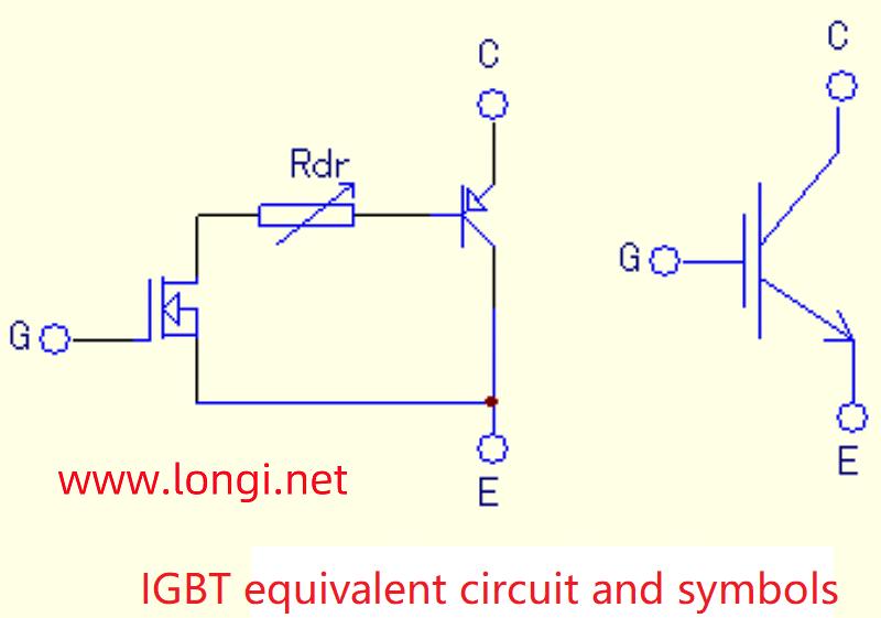
Field effect transistors have the advantages of fast switching speed and voltage control, but they also have the disadvantages of large conduction voltage drop and small voltage and current capacity. However, bipolar devices have exactly the opposite characteristics, such as current control, small conduction and voltage drop, and large power capacity. The combination of the two is known as complementary advantages. The origin of IGBT tubes or IGBT modules is based on this. Structurally, similar to the familiar composite amplifier transistor, the output transistor is a PNP type transistor, while the excitation transistor is a field-effect transistor, and the drain current of the latter forms the base current of the former. The amplification ability is the product of two tubes.
The equivalent circuit and symbols of IGBT tubes are shown in the following figure:
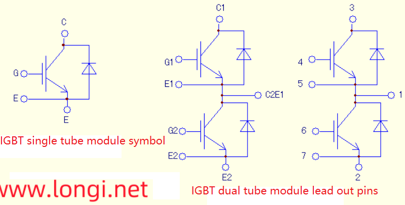
The pin function diagram of commonly used IGBT single and double tube modules (CM200Y-24NF) is as follows:
Pin function diagram of FP24R12KE3 integrated module:
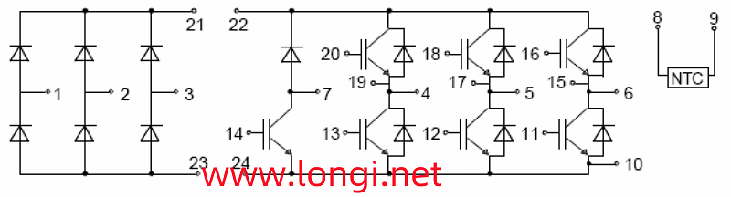
Before disassembling, a rough measurement of the quality of the module can be made to make a preliminary judgment. For example, terminals 4, 5, and 6 are the U, V, and W output terminals of the frequency converter, while terminals 22 and 24 are the P (+) and N (-) terminals of the internal DC main circuit of the frequency converter, respectively. After identifying these 5 terminals, measurements can be made using a digital or pointer type multimeter. U. The V and W terminals all have forward and reverse resistance to the P and N terminals. Under normal conditions of IGBT tubes, the resistance between tubes C and E is infinite. Only the forward and reverse resistance of the six diodes in parallel on the tube can be measured. If terminals 4, 5, and 6 are considered as three-phase AC input terminals, the six diodes are equivalent to a three-phase rectifier bridge circuit. The method of measuring and judging the three-phase rectifier bridge is sufficient.
A. Online measurement:
If the measurement of this three-phase rectifier bridge is abnormal, it indicates that the module is damaged;
It is normal to measure this three-phase rectifier bridge, but it cannot be determined whether the module is good. The main circuit board of the frequency converter should be opened for further measurement and verification. Measure whether the triggering terminal and internal circuit are normal. Due to the fact that a resistor of about 10k (3k in parallel for high-power models) is often connected in parallel on the trigger terminal, both the forward and reverse online resistances of the trigger terminal should be the resistance value of the parallel resistor. The resistance values of these 6 trigger terminals should be the same. If there is a difference in the forward and reverse resistance of a certain triggering terminal, or if there is a decrease in resistance, after ruling out the fault of the driving circuit, it indicates that the module has been damaged.
The resistance measurement of the triggering terminal is also normal, and in general, the module is considered to be basically good. But it seems too early to announce that the module is absolutely fine at this time. See later on.
B. Offline measurement:
- This method is commonly used for measuring high-power single and dual modules, as well as newly purchased integrated modules.
After disconnecting the single and double transistor modules from the circuit (or for newly purchased modules), the measurement field-effect transistor (MOSFET) method can be used for testing. There is a junction capacitance between the gate and cathode of MOSFET, which determines its extremely high input impedance and charge retention function. This feature can be effectively used to detect the quality of IGBT tubes.
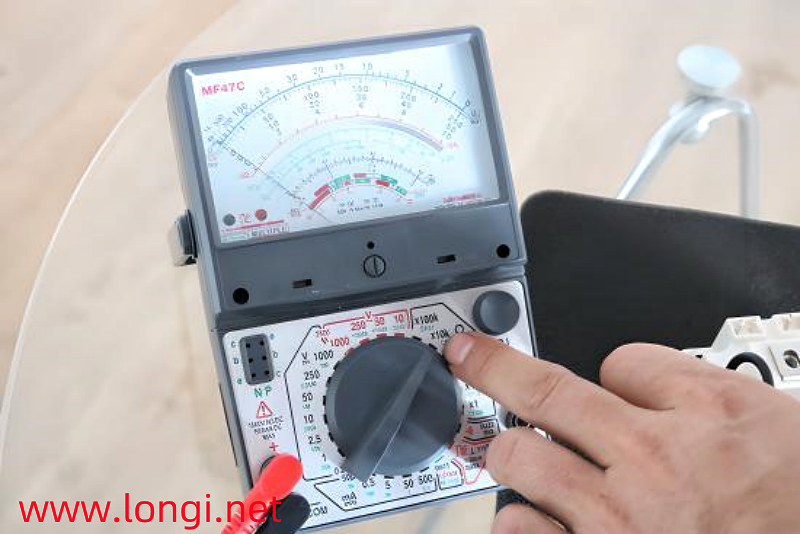
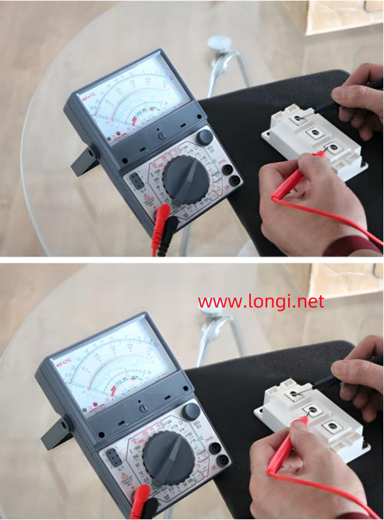
The method is to set the pointer type multimeter to x10k, connect the black meter to pole C, and the red meter to pole E. At this point, the measured resistance value is almost infinite; Set up the pen without moving, touch the C and G poles with your fingers and remove them, indicating a decrease in resistance from infinity to around 200k; After a few seconds or even longer, measure the resistance between C and E again (with the black probe still connected to the C pole), which can still protect the resistance of about 200k from changing; Set up the pen without moving, short circuit the G and E poles with your finger, and the resistance between the C and E poles will become close to infinity again.
In fact, touching C and G with your finger charges the gate and anode capacitors. After removing your finger, there is no discharge circuit for the capacitor, so the charge on the capacitor can be maintained for a period of time. The charging voltage on this capacitor is a forward excitation voltage, causing slight conduction of the IGBT tube and reducing the resistance between C and E; When shorting G and E with your fingers for the second time, a discharge path for the capacitor is provided. As the charge is discharged, the excitation voltage of the IGBT disappears, the tube becomes cut off, and the resistance between C and E tends to infinity.
Fingers are equivalent to a resistance of k Ω level, providing a path for charging and discharging gate cathode junction capacitors; Due to the high forward excitation voltage (above 10V) required for the conduction of IGBT tubes, the x10k range of the multimeter is used, and the internal battery power supply in this range is 9V or 12V to meet the amplitude of the IGBT tube excitation voltage.
The measurement of trigger terminals can also be measured with a capacitance meter to increase the accuracy of judgment. Often, modules with high power capacity have slightly higher capacitance values between the two terminals. - Below are the dual tube modules CM100DU-24H and SKM75GB128DE, as well as the integrated module FP24R12KE3, using an MF47C pointer multimeter, × Data measured at 10k levels:
CM200Y-24NF module: main terminal C1, C2E1 E2 trigger terminal C1 E1 C2 E2; After triggering, the resistance for C and E is 250k;
The measurement using a capacitance meter in the 200nF range is 36.7nF, and the reverse measurement (with the black pen connected to the G terminal and the red pen connected to the E terminal) is 50 nF.
The main terminal of SKM75GB128DE is the same as above, and after triggering, the C and E resistances are 250k;
Trigger terminal capacitance: Measure 4.1 nF forward and 12.3 nF backward.
FP24R12KE3 integrated module, this method can also be used, with a C and E resistance of around 200k after triggering;
Trigger terminal capacitance forward measurement 6.9 nF, reverse measurement 10.1 nF.
C. The power on measurement after online or offline measurement can finally determine the quality of the module:
Repair a 37kW Dongyuan frequency converter. Upon inspection, it was found that the inverter module was damaged, with model CM100DU-24H. After purchasing a module of the same type, I went through all the offline measurement procedures and confirmed that there were no issues with the module before installing it for testing. The three-phase output voltage is very unbalanced. After thoroughly checking the drive circuit to confirm that there are no faults, measure the zero line of the three-phase power supply from the U, V, and W outputs (using a pointer type multimeter in the DC 500V range). The DC components of the U and W phases are zero, while the V phase has a DC negative pressure of about 300V. From this, it can be concluded that the conduction of the V-phase lower tube is good, while the conduction of the upper tube is poor, resulting in a negative voltage output of V relative to the zero line. And the V-phase upper tube happens to be the newly replaced module. After purchasing another CM100DU-24H for replacement, the three-phase output is normal. The malfunction of the tube is that the internal MOSEFT tube is normal, so online or offline measurements are normal, while the internal output C and E poles have increased internal resistance due to conduction. It illustrates one thing that even after careful measurement, it cannot be 100% concluded that there is no problem with a good inverter module. The measurement and judgment ability of a multimeter is limited after all. Do not have preconceptions about the problems reflected after powering on the connected circuit, thinking that the module cannot be faulty, which can lead to false disconnection of the fault and lead to a detour in maintenance!