
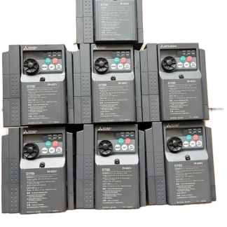
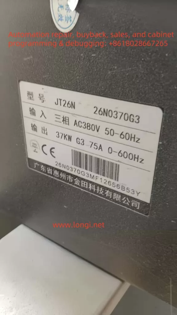
The JTE Inverter JT26N series is a high-performance general-purpose inverter widely used in various industrial control scenarios. This article provides a detailed introduction to the usage of this inverter, including panel startup and speed adjustment settings, external terminal forward/reverse and external potentiometer speed adjustment settings, parameter copying and initialization methods, as well as the meaning and resolution of the ERR10 fault.
I. Basic Settings for the JTE Inverter JT26N
1. Panel Startup and Speed Adjustment Settings
The panel startup and speed adjustment settings for the JTE Inverter JT26N are relatively straightforward. Users can complete basic startup and speed adjustment operations through the buttons and display on the control panel. Here are the specific steps:
- Startup Settings:
- Press the “PRGM” key to enter programming mode.
- Use the “Δ” and “∇” keys to select the function code F0-02, and confirm that the command source is set to the control panel command channel (value 0).
- Press the “ENTER” key to confirm the setting.
- Speed Adjustment Settings:
- In programming mode, select the function code F0-03 and set the main frequency source X to panel potentiometer speed adjustment (value 1).
- Adjust the frequency by rotating the potentiometer on the panel to achieve speed control.
2. External Terminal Forward/Reverse and External Potentiometer Speed Adjustment Settings
The JTE Inverter JT26N supports forward/reverse control and external potentiometer speed adjustment functions through external terminals. Here are the specific wiring and setup methods:
- Forward/Reverse Control:
- Wiring: Connect the external control signal to the digital input terminals of the inverter (such as MI1, MI2, etc.).
- Settings: In programming mode, select the function code F0-09 and set the running direction to forward (value 0) or reverse (value 1).
- External Potentiometer Speed Adjustment:
- Wiring: Connect the signal line of the external potentiometer to the analog input terminals of the inverter (such as AI1, AI2, etc.).
- Settings: In programming mode, select the function code F0-03 and set the main frequency source X to external potentiometer speed adjustment (value 2, 3, or 4, depending on the specific terminal).
II. Parameter Copying and Initialization
1. Parameter Copying
The JTE Inverter JT26N supports parameter copying, allowing users to copy parameters from one inverter to another. Here are the specific steps:
- Prepare a blank storage card or USB drive and insert it into the parameter copying interface of the inverter.
- Press the “PRGM” key to enter programming mode and select the parameter copying function.
- Follow the prompts to copy the parameters to the storage card or USB drive.
- Insert the storage card or USB drive into another inverter and follow the prompts to copy the parameters to the new inverter.
2. Parameter Initialization
In some cases, users may need to initialize the inverter parameters. Here are the specific steps:
- Press the “PRGM” key to enter programming mode.
- Select the function code F0-27 and set the parameter initialization option to fully initialize parameters (value 03).
- Press the “ENTER” key to confirm, and the inverter will reset to factory settings.
III. Meaning and Resolution of the ERR10 Fault
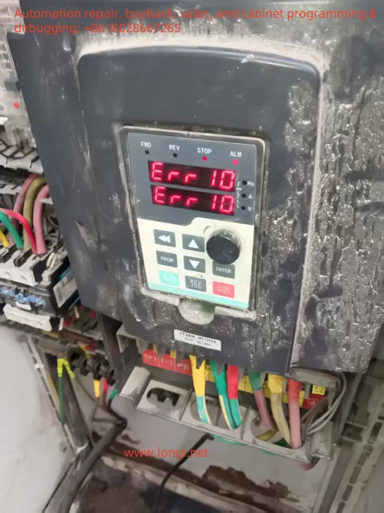
1. Meaning of the ERR10 Fault
The ERR10 fault is a common fault code for the JTE Inverter JT26N, indicating an overload condition. An overload occurs when the output current of the inverter exceeds its rated current, which may be caused by the following reasons:
- The load is too large, exceeding the rated capacity of the inverter.
- There is a mechanical fault in the motor or other load equipment, causing abnormal current increases.
- The parameter settings of the inverter are incorrect, leading to overload protection activation.
2. Handling the ERR10 Fault
When the ERR10 fault occurs on-site, users should follow these steps to address it:
- Check the Load: Ensure that the load is within the rated capacity range of the inverter, reducing the load if necessary.
- Inspect the Motor and Equipment: Check the motor and other load equipment for mechanical faults, such as jamming or excessive resistance.
- Verify Parameter Settings: Ensure that the inverter’s parameter settings are correct, especially those related to the load.
- Restart the Inverter: After confirming that the load and equipment are normal, restart the inverter and observe if the ERR10 fault still occurs.
3. Repair Methods for the ERR10 Fault
When repairing the internal circuit board of the inverter after an ERR10 fault, users should follow these steps:
- Inspect Under Power-Off Conditions: Open the inverter’s casing in a power-off state and inspect the internal circuit board for any visible damage or burnout.
- Clean the Circuit Board: Use a clean cloth or cotton swab dipped in isopropyl alcohol to gently wipe the surface of the circuit board, removing dust and dirt.
- Replace Damaged Components: If any damaged or burned components are found on the circuit board, replace them with new components of the same model.
- Reassemble: After ensuring that the circuit board has no visible faults, reassemble the inverter and perform a functional test.
IV. Conclusion
The JTE Inverter JT26N is a powerful and easy-to-operate inverter suitable for various industrial control scenarios. By correctly setting up panel startup and speed adjustment, external terminal forward/reverse, and external potentiometer speed adjustment, users can easily achieve basic control functions of the inverter. Additionally, the inverter supports parameter copying and initialization functions, making it convenient for users to manage parameters. In the event of an ERR10 fault, users should promptly check the load and equipment and follow the correct procedures for handling and repair to ensure the normal operation of the inverter.