YF6800B Series Yufeng Inverter Manual Key Points Introduction
I. Operation Overview
The Yufeng Inverter YF6800B series boasts a straightforward operation process, primarily encompassing power-on/off and parameter settings. Upon powering on, ensure a stable power supply before initiating the inverter through the start button on the control panel or remote signals. To power off, first halt motor operation via the control panel or remote signals before cutting off the inverter’s power supply for device safety. Regarding parameter settings, users can navigate through the control panel’s buttons or connect to a computer using dedicated software to access the parameter setting mode, enabling precise adjustments to key parameters such as frequency, voltage, and current limits to meet diverse operational demands across various working conditions.
II. Terminal Start Configuration Method
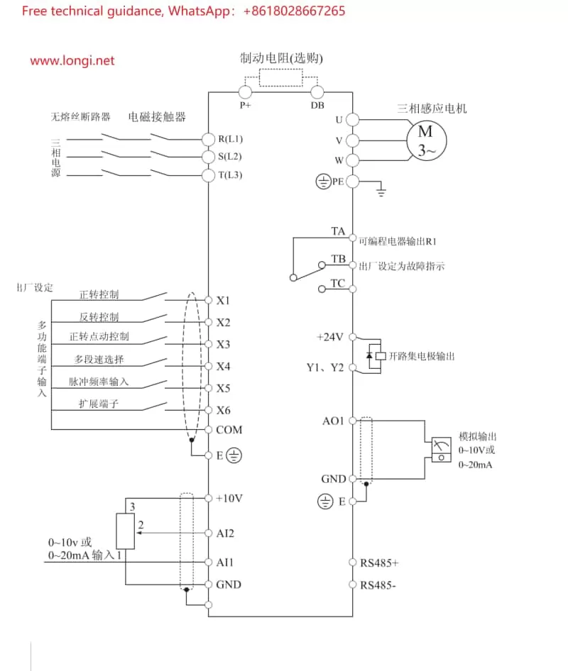
Terminal start represents a commonly utilized control method for inverters, with its setup process encompassing wiring and parameter configuration.
- Wiring: Adhere to the wiring diagram outlined in the manual, connecting the inverter’s RUN (operate) and STOP (halt) terminals to the corresponding output terminals of external control devices like PLCs or buttons. Ensure secure and reliable connections, avoiding looseness or short circuits.
- Parameter Configuration: Navigate to the terminal control-related options within the inverter’s parameter settings to activate terminal control mode. Specific parameter configurations may include:
- Input Point Function Configuration: Assign the RUN and STOP terminals’ corresponding input points to control start and stop operations, respectively.
- Multi-speed Configuration (if applicable): Configure additional input points to correspond with distinct speed segments for multi-speed control.
- Forward/Reverse Configuration (if required): Establish forward and reverse control logic to ensure the motor rotates in the anticipated direction.

III. External Potentiometer Speed Regulation Configuration Method
External potentiometer speed regulation offers a simple and intuitive means of speed adjustment, also encompassing wiring and parameter configuration.
- Wiring: Connect the external potentiometer’s output terminal to the inverter’s analog input terminal (e.g., AI1), with the potentiometer’s ends respectively wired to power and ground, forming a complete circuit. Select an appropriate power supply voltage and potentiometer resistance range to ensure precision and stability in speed regulation.
- Parameter Configuration: Locate the analog input-related options within the inverter’s parameter settings for the following configurations:
- Input Source Configuration: Assign AI1 as the speed reference source.
- Input Range Configuration: Match the inverter’s input range with the potentiometer’s output range.
- Gain Configuration: Adjust the gain parameter to alter speed regulation sensitivity, facilitating smooth motor speed adjustment according to the potentiometer’s output.
IV. Fault Diagnosis and Resolution Methods
During the utilization of the Yufeng Inverter YF6800B, various faults may arise. Below are some common faults and their corresponding diagnosis and resolution methods:
- Overcurrent Protection: Inspect if the motor and load are excessively large or short-circuited, adjusting the load or replacing the motor as necessary. Additionally, verify if the inverter’s output current settings are reasonable.
- Overvoltage/Undervoltage Protection: Check if the input power supply voltage remains stable within the specified range. If voltage fluctuations are significant, implement voltage stabilization measures.
- Overheat Protection: Ensure the inverter’s cooling fan operates normally, cleaning dust and debris from the heat sink. If the ambient temperature is excessively high, adopt cooling measures.
- Communication Failure: Verify the secure and reliable connection of communication lines, along with accurate communication parameter settings. Attempt to restore communication by re-powering or restarting the device.
- Control Malfunction: Inspect if the control signal input is accurate and the control logic aligns with the set requirements. For complex control logic, utilize professional tools for fault location and analysis.
By adopting these methods, users can swiftly diagnose and resolve faults encountered during inverter operation, ensuring safe and stable device functioning.
