
Kingda Inverter V380 Series User Manual Operation Guide
I. Introduction to Inverter Operation Panel Functions and Factory Reset
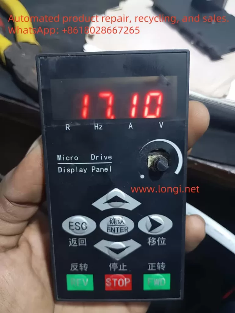
The Kingda Inverter V380 series features a versatile operation panel with the following main keys:
- Run/Stop Key: Used to start or stop the inverter.
- Forward/Reverse Key: Used to control the motor’s forward and reverse rotation, respectively.
- Stop/Fault Reset Key: Used to reset or stop the inverter in case of a fault.
- Return Key: Used to switch between monitoring modes or return to the previous state.
- Confirm Key: Confirms the current status or parameter and enters the next level of the function menu.
- Data Modify Key: Used to modify function codes or parameters.
- Shift Key: Used to move the cursor position when setting parameters.
Factory Reset:
- To restore factory settings, enter the parameter settings interface, find the
P0.03parameter (Parameter Initialization), set it to1, and then press the confirm key to execute the initialization. This operation will clear all user-defined parameters, and the inverter will revert to its factory default settings.
Carrier Frequency and Carrier Characteristic Parameters:
- Carrier Frequency: Refers to the frequency of the PWM (Pulse Width Modulation) signal within the inverter, affecting the harmonic content of the output current and motor noise levels. A higher carrier frequency reduces harmonic content but increases switching losses, potentially leading to increased inverter heat generation.
- Carrier Characteristic Parameter (
P0.12): Controls whether the carrier frequency changes with the output frequency. When set to0, the carrier frequency does not change with the output frequency; when set to1, the carrier frequency increases with the output frequency, helping to reduce noise and vibration at lower frequencies. - Setting Carrier Frequency: Enter the parameter settings interface, find the
P0.11parameter (Carrier Frequency), and adjust its value according to actual needs, typically ranging from 0.8 to 15.0 KHz.
II. Terminal Start/Stop and External Potentiometer Speed Regulation Settings
Terminal Start/Stop:
- Wiring: Connect external control signals to the inverter’s DI (Digital Input) terminals. Typically, the forward start signal is connected to DI1, the reverse start signal to DI2, and the stop signal to DI3 (or a combination of states shared by DI1 and DI2).
- Parameter Settings: Enter the parameter settings interface and set
P1.05(Run Command Channel) to1(Terminal Control Start/Stop).
External Potentiometer Speed Regulation:
- Wiring: Connect the output of the external potentiometer to the inverter’s AI1 (Analog Input 1) terminal. The sliding end of the potentiometer is used to adjust the output voltage, thereby controlling the inverter’s output frequency.
- Parameter Settings: Enter the parameter settings interface, set
P1.00(Main Frequency Channel A Selection) to3(Panel Potentiometer), and setP2.00andP2.01to the lower and upper voltage limits of AI1 input, respectively.
III. Modbus Protocol Settings and PID Control via Siemens PLC (S7-200)
To achieve PID control (e.g., single-pump constant pressure water supply) of the inverter via a Siemens PLC (S7-200) using the Modbus protocol, the following settings are required:
- Modbus Parameter Settings:
- Enter the parameter settings interface, set the units place of
P9.00(Communication Settings) to the corresponding baud rate (e.g.,4for 9600 bps), and the tens place to the data format (e.g.,0for no parity). - Set
P9.01(Device Address) to the Modbus address of the inverter. - Ensure
P9.04(Communication Timeout Fault Detection Time) is set reasonably to avoid communication interruptions.
- Enter the parameter settings interface, set the units place of
- PID Control Parameter Settings:
- Enter the parameter settings interface and enable the built-in PID control (
P8.00set to a non-zero value). - Set the PID setpoint and feedback channels (
P8.01), typically selecting the external voltage signal AI1 as the feedback channel. - Adjust PID proportional constant (
P8.07), integral constant (P8.08), and other parameters according to control requirements.
- Enter the parameter settings interface and enable the built-in PID control (
- PLC Programming:
- Write a Modbus communication program in the Siemens PLC (S7-200) to read the current status of the inverter and send PID setpoints.
- Write a PID control algorithm program to adjust the setpoint based on the feedback signal, achieving control objectives such as constant pressure water supply.
IV. Fault Code Analysis and Solutions
The Kingda Inverter V380 series features comprehensive fault protection. When a fault occurs, the inverter displays the corresponding fault code. Below are some common fault codes, their analysis, and solutions:
- EC.01: Overcurrent during acceleration. Possible causes include too short an acceleration time, an inappropriate V/F curve, etc. Solutions include extending the acceleration time, adjusting the V/F curve, etc.
- EC.02: Overcurrent during deceleration of the inverter. A possible cause is too short a deceleration time. The solution is to increase the deceleration time.
- EC.03: Overcurrent during inverter operation or stoppage. Possible causes include sudden load changes, low grid voltage, etc. Solutions include reducing load fluctuations and checking the power supply voltage.
- EC.04 to EC.07: Related to overvoltage faults, possible causes include abnormal power supply voltage, improper deceleration time settings, etc. Solutions include checking the power supply voltage and adjusting the deceleration time.
- EC.12 and EC.13: Indicate inverter and motor overload, respectively. Possible causes include excessive load, too short an acceleration time, etc. Solutions include reducing the load and extending the acceleration time.
For other fault codes, refer to the Fault Diagnosis and Countermeasures section of the user manual for detailed analysis and solutions. When troubleshooting, ensure that the inverter is powered off and take necessary safety measures.
V. Conclusion
This document provides a detailed introduction to the operation guide of the Kingda Inverter V380 series, including the operation panel function introduction, factory reset method, carrier frequency and carrier characteristic parameter settings, terminal start/stop and external potentiometer speed regulation settings, Modbus protocol and PLC PID control settings, as well as fault code analysis and solutions. With this guide, users can better understand and utilize this inverter to achieve efficient and stable motor control.