
I. Introduction to the Operation Panel Functions and Parameter Settings
Operation Panel Functions
The LS Inverter SV-iGxA series features an intuitive operation panel that includes RUN, STOP/RESET, up and down arrow keys, as well as a confirmation key. The panel’s 7-segment LED display provides clear visual feedback on operational data and parameter settings. Here’s a detailed look at the functions of the operation panel:
- RUN Key: Starts the motor when pressed.
- STOP/RESET Key: Stops the motor during operation and resets fault conditions when pressed after a fault occurs.
- Arrow Keys: The up and down arrow keys are used to navigate through parameters and adjust their values.
- Confirmation Key: Confirms parameter settings and saves changes.
- 7-Segment LED Display: Shows operational data such as output frequency, output current, and fault codes.
Parameter Initialization
To initialize the parameters to their factory default settings, follow these steps:
- Navigate to Parameter H93: Use the arrow keys to select parameter H93 (Parameter Initialization) in the function group 2.
- Set Initialization Value: Press the confirmation key to enter the setting, then use the arrow keys to select the desired initialization level (e.g., 1 for initializing all parameter groups).
- Confirm Initialization: Press the confirmation key again to save the setting and initialize the parameters.
Reading, Writing, and Copying Parameters
The SV-iGxA series supports reading and writing parameters using a remote panel or communication interface.
- Reading Parameters:
- Navigate to parameter H91 (Parameter Read) in the function group 2.
- Press the confirmation key to initiate the parameter read process.
- Follow the prompts on the remote panel or software interface to complete the read operation.
- Writing Parameters:
- Navigate to parameter H92 (Parameter Write) in the function group 2.
- Press the confirmation key to initiate the parameter write process.
- Follow the prompts on the remote panel or software interface to upload the new parameter settings to the inverter.
Setting a Password and Locking Parameters
To enhance security, the SV-iGxA series allows users to set a password and lock specific parameters.
- Registering a Password:
- Navigate to parameter H94 (Password Registration) in the function group 2.
- Press the confirmation key to enter the setting.
- Use the arrow keys to input the desired password (in hexadecimal format).
- Press the confirmation key to save the password.
- Locking Parameters:
- Navigate to parameter H95 (Parameter Lock) in the function group 2.
- Press the confirmation key to enter the setting.
- Use the arrow keys to select the desired lock level (e.g., locking all parameters by setting H95 to 0xFFFF).
- Press the confirmation key to save the setting and lock the parameters.
II. Terminal Control and Potentiometer Speed Regulation
Terminal Forward/Reverse Control
To achieve forward/reverse control via terminal inputs, the following parameters need to be configured:
- drv (Drive Mode): Set to 1 to enable terminal control.
- drC (Motor Rotation Direction Selection): Select the desired rotation direction (F for forward, r for reverse).
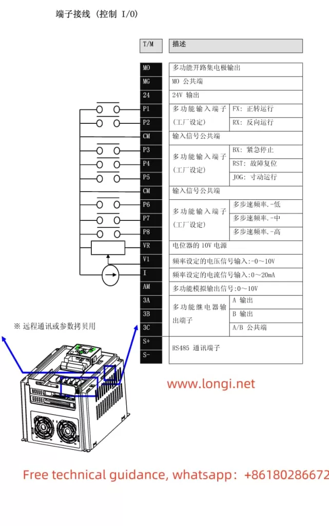
- I17-I18 (Multi-Function Input Terminal Definitions): Assign the FX (forward) and RX (reverse) commands to specific terminals (e.g., P1 for FX and P2 for RX).
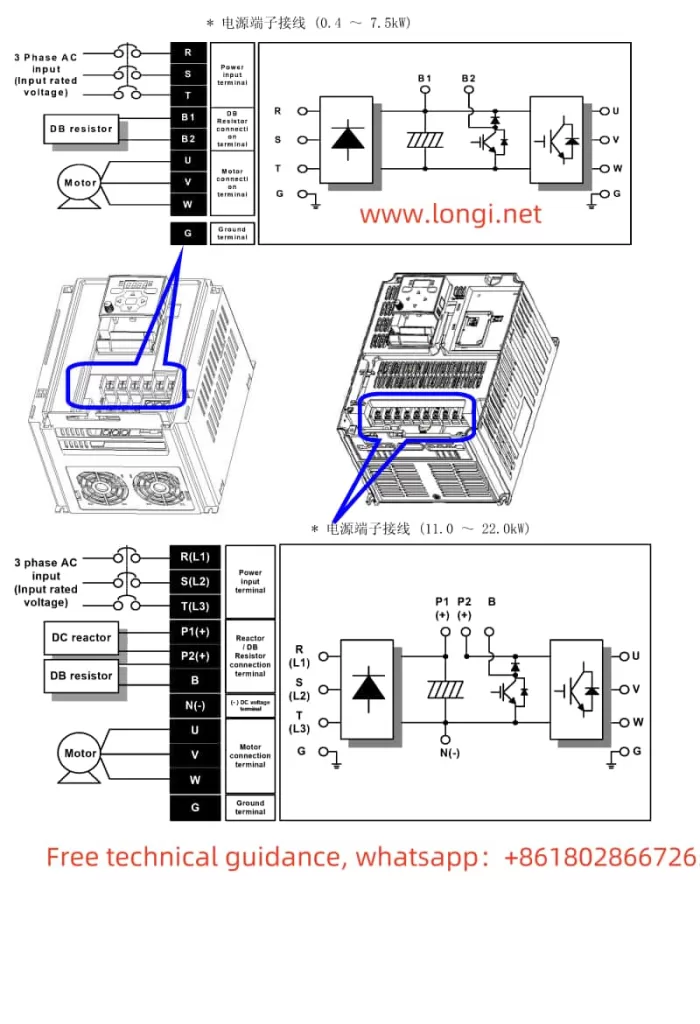
Required Wiring:
- FX Terminal: Connect to a normally open (NO) contact to start the motor in the forward direction.
- RX Terminal: Connect to a normally open (NO) contact to start the motor in the reverse direction.
- CM (Common) Terminal: Provide a common ground connection for all input terminals.
Potentiometer Speed Regulation
For speed regulation using a potentiometer, the following parameters need to be configured:
- Frq (Frequency Mode): Set to 3 to enable potentiometer input for frequency control.
- I6-I10 (V1 Input Parameters): Configure the voltage range and corresponding frequency for the potentiometer input.
- I7 (V1 Input Minimum Voltage): Set to the minimum voltage output by the potentiometer.
- I8 (V1 Input Minimum Frequency): Set the frequency corresponding to the minimum voltage.
- I9 (V1 Input Maximum Voltage): Set to the maximum voltage output by the potentiometer.
- I10 (V1 Input Maximum Frequency): Set the frequency corresponding to the maximum voltage.
Required Wiring:
- V1 Terminal: Connect to the output of the potentiometer.
- CM Terminal: Provide a common ground connection for the V1 terminal.
- 10V Terminal (if applicable): Provide a 10V reference voltage for the potentiometer (not required for potentiometers with built-in reference voltage).
By configuring the above parameters and wiring the terminals correctly, the SV-iGxA series inverter can be easily controlled via external inputs for forward/reverse operation and speed regulation using a potentiometer.