1. Introduction to Inverter Panel Functions and Parameter Settings
1.1 Panel Function Introduction
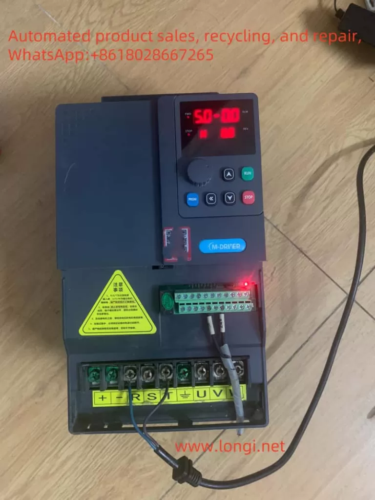
The M-DRIVER INVERTER M900 series features an intuitive and user-friendly panel design, with key functions including:
- Running Indicators: Display the inverter’s operating status, such as Forward (FWD), Reverse (REV), and Stop (STOP).
- Fault Indicator (ALM): Lights up when the inverter encounters a fault, prompting the user to check.
- Program Key (PRGM): Used to enter or exit the parameter setting interface.
- Enter Key (ENTER): Confirms parameter modifications or accesses the next menu level.
- Increment Key (▲) and Decrement Key (▼): Adjust parameter values or select menu items.
- Shift Key (<<): Toggles between digit positions during parameter modification.
- Run Key (RUN) and Stop Key (STOP/RESET): Start and stop the inverter, respectively.

1.2 Restoring Factory Default Parameters
Restoring factory default parameters resets the inverter to its initial state. The steps are as follows:
- Press the Program Key (PRGM) to enter the parameter setting interface.
- Use the Increment Key (▲) or Decrement Key (▼) to select parameter F0-24.
- Press the Enter Key (ENTER) to enter the parameter modification interface.
- Set the value of F0-24 to 1.
- Press the Enter Key (ENTER) again to save the setting and exit.
1.3 Setting and Removing Passwords
To protect the inverter parameters from unauthorized modification, a user password can be set:
- Enter the parameter setting interface and select parameter F6-03.
- Press the Enter Key (ENTER) to enter the password modification interface.
- Use the Increment Key (▲) or Decrement Key (▼) to set the password.
- Press the Enter Key (ENTER) again to save the password.
To remove the password, simply set the value of F6-03 to 0.
1.4 Setting Parameters for Synchronous Motor Control
When using the M900 series inverter to control a synchronous motor, the following parameters need to be set:
- F8-06: Motor Control Mode, set to “2” (Synchronous Motor Vector Control without Speed Sensor).
- F8-07: Motor Parameter Self-Tuning, select “Static Parameter Tuning” or “Dynamic Parameter Tuning” based on the motor state.
- F8-16 to F8-18: Enter the synchronous motor’s stator resistance, d-axis inductance, and q-axis inductance parameters (if available on the nameplate, input directly; otherwise, perform parameter tuning).

2. Terminal Forward/Reverse and External Potentiometer Speed Control
2.1 Wiring Instructions
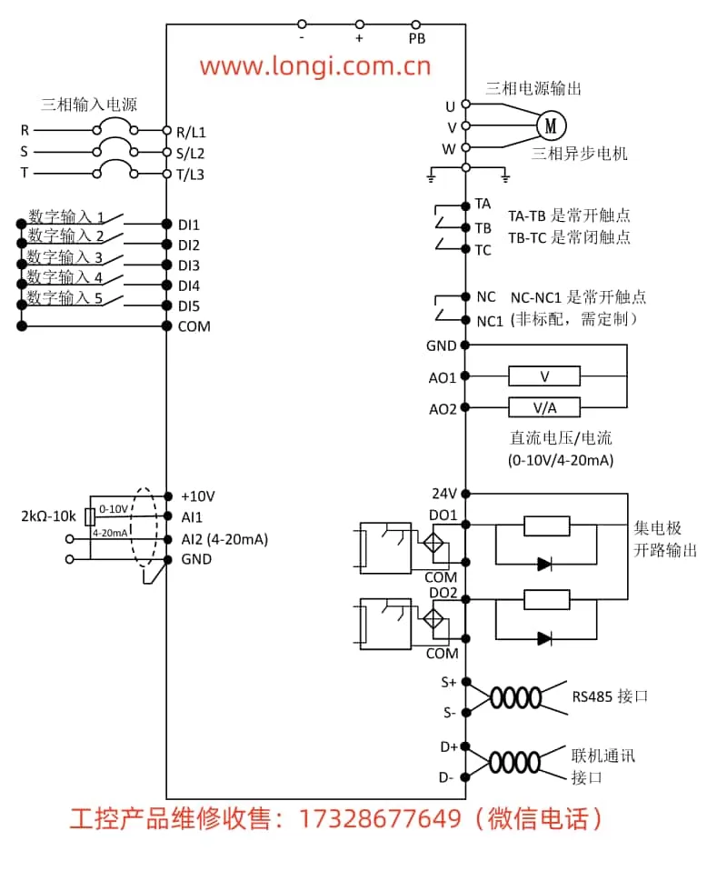
- Forward/Reverse Control: Connect external switches to the inverter’s DI1 and DI2 terminals, with GND as the common terminal.
- External Potentiometer Speed Control: Connect the potentiometer’s three terminals to the inverter’s AI1, GND, and +10V terminals, respectively.
2.2 Parameter Settings
- Enter the parameter setting interface and select F0-00, setting its value to “1” (Terminal Control).
- Select F1-00 and F1-01, setting the functions of DI1 and DI2 to Forward (FWD) and Reverse (REV), respectively.
- Select F0-01 and set its value to “2” (AI1 as the frequency source).
- Adjust the gain (F1-24) and offset (F1-25) of AI1 as needed to ensure the appropriate speed control range.
3. Modbus Communication and Siemens PLC SMART Control
3.1 Communication Parameter Settings
- Enter the parameter setting interface and select F7-00 to set the inverter’s device address.
- Select F7-01 to set the baud rate (e.g., 9600BPS).
- Select F7-02 to set the data format (e.g., no parity, even parity, etc.).
- Select F7-03 to set the communication timeout period.
3.2 PLC Control Settings
In the PLC programming software, send control commands to the inverter via the Modbus protocol. For example, to achieve forward/reverse control, the following commands can be sent:
- Forward: Write the number “1” to the inverter’s 2nd register.
- Reverse: Write the number “2” to the inverter’s 2nd register.
Ensure that F0-00 is set to “2” (Communication Control) and F0-01 is set to “8” (Communication Setting) to allow the inverter to receive control commands from the PLC.
4. Fault Code Meaning Analysis and Resolution Methods
4.1 Example Fault Codes
- Err01: Inverter Unit Protection. Possible causes include output circuit short-circuit, excessive length of motor and inverter wiring, etc. Solutions include troubleshooting peripheral faults, installing reactors or output filters, etc.
- Err02: Acceleration Overcurrent. Possible causes include output circuit grounding or short-circuit, too short acceleration time, etc. Solutions include increasing the acceleration time, adjusting the manual torque boost or V/F curve, etc.
- Err10: Inverter Overload. Possible causes include excessive load or motor lock. Solutions include reducing the load and checking the motor and machinery, or selecting an inverter with a higher power rating.
4.2 Fault Handling Process
- Check Fault Code: When a fault code appears on the inverter panel, first record it and consult the fault code table in the manual.
- Analyze Possible Causes: Based on the fault code table, analyze the possible causes of the fault.
- Take Corrective Measures: Follow the suggestions in the manual or combine them with actual conditions to take appropriate corrective measures.
- Verify Repair Effectiveness: After resolving the fault, restart the inverter and verify that it has returned to normal operation.
5. Conclusion
The M-DRIVER INVERTER M900 Series User Manual provides detailed usage guides and parameter setting instructions. Through this guide, users can learn about panel functions, parameter restoration, password setting, synchronous motor control, terminal wiring and settings, Modbus communication, and fault handling. In practical applications, users should strictly follow the instructions in the manual to ensure the normal operation and long-term stability of the inverter.
