
There is a separate MCU and six communication optocouplers OI1~OI6 on the power drive board of Mitsubishi F700 (F740, F720) and A700 (A740, A720) frequency converters. Their specifications look a bit mysterious and may cause confusion during maintenance. The relevant circuit diagram will be drawn below, and a simple functional analysis of the MCU and optocoupler will be conducted to reduce the difficulty of repairing and changing the frequency converter.
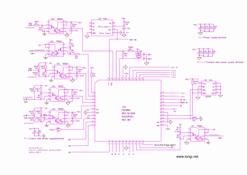
OI6:
Responsible for transmitting the operation and shutdown instructions of the motherboard MCU, with instructions in the form of 1 and 0 levels. The 19 pin of CON1 is a 5V high level, which is a running command. The output side of OI1 becomes 0V, and the local MCU can send 6 pulse signals such as U+~W – to the driving circuit; The 19 pin of CON1 is at 0V low voltage level, and the motherboard MCU sends a shutdown command (if it becomes low during operation, the OI1 output side becomes 5V, which is an overload fault shutdown command). The messenger of the motherboard MCU sends running and stopping commands to the local MCU in the form of DC
The 0 and 1 levels of opening and closing quantities.
OI2:
The serial data returned by the local MCU and motherboard MCU is in the form of rectangular wave pulses. Start working immediately after powering on.
The communicator between the local MCU and the motherboard MCU, signal direction: transmitted locally to the motherboard MCU.
OI5:
The communicator between the motherboard MCU and the local MCU, signal direction: The motherboard MCU issues instructions to the local MCU
MCU. The signal form is serial data, and the test is a rectangular pulse train. Start working immediately after powering on.
OI4:
The main board MCU sends switching instructions to the local MCU, and under normal conditions (running and stopping), the output terminal 6 pins are 0V. When it reaches 5V high level, an E7 code (meaning CPU error) is reported. Is its task to confirm the working status of the motherboard MCU?
OI3:
The communication personnel between the motherboard MCU and the local MCU, signal direction: The motherboard MCU issues instructions to the local MCU. The input signal is in the form of serial data (synchronous clock signal?), but due to the capacitance integration effect at pins 5 and 6, a triangular wave of 760kHz is measured. Start working immediately after powering on.
OI1:
The communication personnel between the local MCU and the motherboard MCU, signal direction: The local MCU reports the fault situation to the motherboard MCU. Signal form 0, 1 switch quantity DC voltage. The shutdown status between pins 5 and 6 of the output terminal is 0V, which changes to a high level of 5V after operation. When there is a fault, it changes to 0V and displays the alarm code EOC1.
As a module fault reporter, he reports the fault situation to the motherboard MCU.