
I. Main Circuit Wiring Instructions
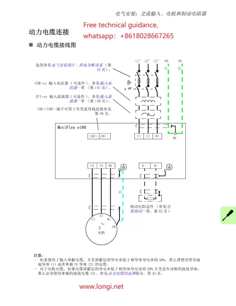
- Power Supply Wiring
- The MotiFlex e180 servo drive supports three-phase AC power input, typically ranging from 200V to 480V AC, depending on the selected model.Before wiring, ensure the power supply is switched off and disconnected to avoid the risk of electric shock.
- Wiring Steps:
- Verify that the power supply voltage and frequency meet the drive requirements.
- Connect the three phases (L1, L2, L3) and ground wire (PE) of the power supply to the drive’s input terminals using appropriately sized cables.
- Ensure secure cable connections and check that the cable shielding is properly grounded.
- Motor Wiring
- Connect the motor cable to the drive’s motor output terminals (U, V, W), ensuring the motor ground wire (PE) is also properly connected.
- Check that the motor model and rated parameters match the drive.
- Use appropriately sized motor cables to connect the three-phase wires (U, V, W) and ground wire (PE) to the corresponding output terminals of the drive.
- Tighten the cable connectors to ensure a reliable connection.
II. Control Circuit Wiring Instructions
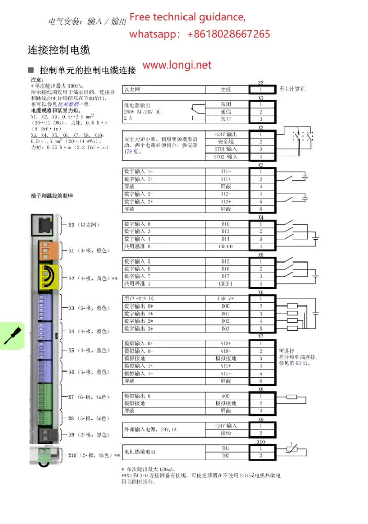
- I/O Interface Description
- The MotiFlex e180 provides a rich set of I/O interfaces, including Digital Input (DI), Digital Output (DO), Analog Input (AI), and Analog Output (AO) for communication and control with external devices or controllers.
- DIs receive switching signals from external devices, such as start, stop, and emergency stop.
- DOs send control signals to external devices, such as alarm output and motor running status indication.
- AIs receive analog signals, such as speed setting and position feedback.
- AOs output analog signals, such as drive current and voltage feedback.
- Control Circuit Wiring
Wiring Steps:- Prepare suitable control cables, ensuring that the cable specifications and length meet the requirements.
- Connect the control cables to the corresponding I/O interfaces according to the drive wiring diagram. Pay attention to distinguishing between inputs and outputs, as well as positive and negative polarity.
- For digital outputs requiring external power (e.g., relay outputs), ensure that the external power specifications meet the requirements and are correctly wired.
III. Debugging MotiFlex e180 Servo Drive with Mint WorkBench
- Installing and Configuring Mint WorkBench
- Download and install Mint WorkBench software: Obtain the latest version of Mint WorkBench from the ABB official website and follow the installation guide to complete the installation.
- Connect the drive: Use an Ethernet cable to connect the computer to the MotiFlex e180’s E3 port, and configure the computer’s network adapter to ensure it is in the same subnet as the drive’s IP address.
- Starting and Debugging
- Launch Mint WorkBench, create a new project, and select to connect to the MotiFlex e180 servo drive.
- Run the debugging wizard: In Mint WorkBench, start the debugging wizard, follow the prompts to input motor and drive parameters, and proceed with automatic adjustment and performance testing.
- Monitoring and Adjustment: Use the monitoring window to view the drive status in real-time and make manual adjustments as needed to optimize drive performance.
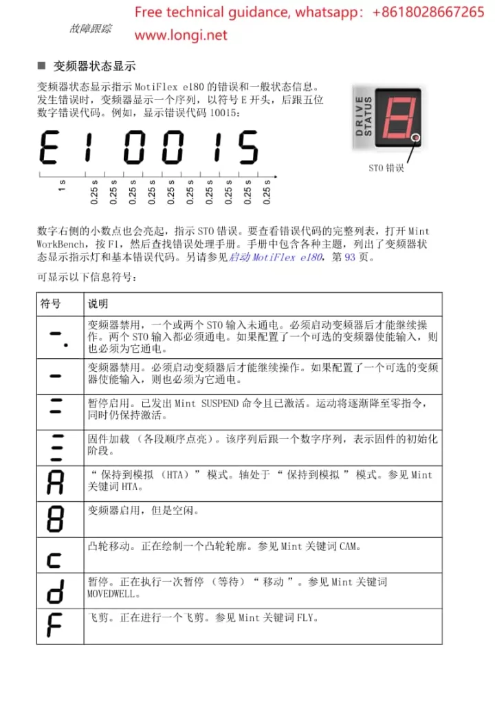
IV. Fault Code Analysis and Solutions
- Error Code 10033 (ecSTO_ACTIVE): Indicates that the STO (Safe Torque Off) function is active.
- Cause: The STO input signal is not energized.
- Solution: Check the wiring and power supply of the STO input signal to ensure normal operation.
- Error Code 10015 (Overcurrent Protection): Indicates that the drive has detected an overcurrent condition.
- Cause: Excessive motor load, motor or cable short circuit, etc.
- Solution: Inspect motor and cable connections, ensure no short circuits or overloads; adjust the load or reduce the operating speed.
- Error Code 20006 (Axis Alarm): Indicates abnormal encoder feedback data.
- Cause: Incorrect encoder wiring, encoder failure, or interference with the feedback signal.
- Solution: Check encoder wiring, replace faulty encoders, or increase signal shielding measures.
By following these steps, you can effectively debug the MotiFlex e180 servo drive using Mint WorkBench and resolve common fault issues. For further questions, please contact us for a detailed manual or free technical support.