
I. Introduction to Operation Panel Functions
The Invt IPE100 Series Engineering Inverter is equipped with an intuitive and user-friendly operation panel, featuring the following key functions:
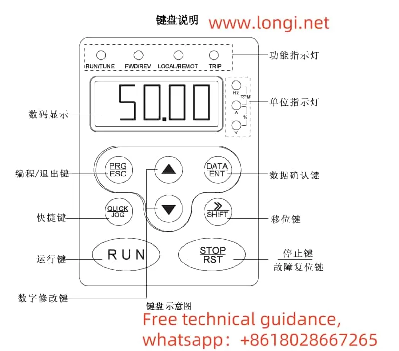
- PRC/ESC (Program/Escape Key): Used to enter or exit the primary menu and delete quick parameters. This key facilitates menu navigation and parameter management during programming or debugging.
- DATA/ENT (Enter Key): Navigates through menu screens level by level and confirms parameter settings. It is essential for making and modifying parameter settings.
- ↑ (Up Key): Increments data or function codes. Used to conveniently increase numerical values when adjusting parameters.
- ↓ (Down Key): Decrements data or function codes. Corresponds to the Up Key for decreasing parameter values.
- 》/SHIFT (Shift Key): Cycles through display parameters in both stop and run display modes. During parameter modification, it selects specific digits for editing, providing flexibility in parameter editing.
- RUN (Run Key): Initiates inverter operation in keyboard control mode. It is a primary control for the inverter’s running state.
- STOP/RST (Stop/Reset Key): Halts inverter operation during runtime. In fault alarm states, it resets faults regardless of function code P7.04 settings.
- QUICK/JOG (Quick/Jog Key): Its function is determined by function code P7.03. When P7.03=0, it activates jogging mode (keyboard control only); when P7.03=1, it toggles between forward and reverse rotation (keyboard control only). Simultaneous pressing of RUN and STOP/RST keys initiates a free stop.
II. Terminal Start and External Potentiometer Speed Control Setup
- Parameter Settings:
- P0.00=2: Selects V/F control mode, suitable for most general-purpose motors.
- P0.01=1: Enables terminal command mode for inverter start/stop control.
- P0.02=1: Selects analog input A1 for speed command, allowing speed regulation via an external potentiometer.
- Motor Parameter Input:
- Enter the following parameters based on the motor nameplate: P2.00 (motor type), P2.01 (motor rated power), P2.02 (motor rated frequency), P2.03 (motor rated speed), P2.04 (motor rated voltage), and P2.05 (motor rated current).
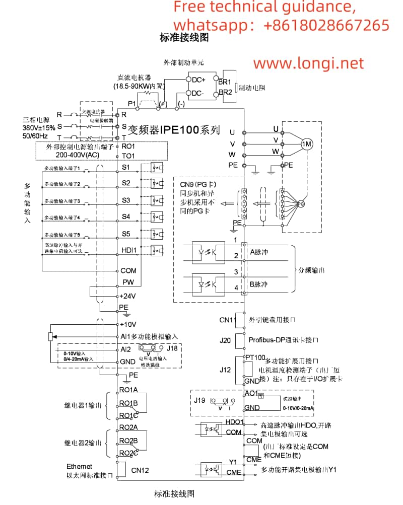
- Wiring Instructions:
- Connect one end of the start switch (or stop switch) to inverter terminal S1 and the other end to terminal COM (ground). Shorting S1 and COM activates the inverter.
- Connect the wiper of the potentiometer to terminal AI1, and the potentiometer ends to terminals +10V and GND, respectively. Turning the potentiometer clockwise accelerates the inverter, while turning it counterclockwise decelerates it.
III. Inverter Fault Code Analysis and Troubleshooting
- Output Faults (OUT1, OUT2, OUT3): Correspond to faults in phases U, V, and W, respectively. Causes may include rapid acceleration, inverter unit issues, or IGBT internal damage. Check for strong interference from peripheral devices and ensure proper motor and cable connections.
- Overcurrent Faults (OC1, OC2, OC3): Correspond to overcurrent during acceleration, deceleration, and constant speed operation, respectively. Check for excessive motor load, motor blockage, or improper parameter settings.
- Overvoltage Faults (OV1, OV2, OV3): Correspond to overvoltage during acceleration, deceleration, and constant speed operation, respectively. Verify the power supply voltage and ensure proper functioning of braking resistors and braking units.
- Undervoltage Fault (UV): Indicates that the bus voltage is below the set value. Check the input power stability and power line connections.
- Overload Faults (OL1, OL2): Correspond to motor overload and inverter overload, respectively. Verify motor load and inverter cooling conditions.
- Phase Loss Faults (SPI, SPO): Correspond to input and output phase loss, respectively. Inspect power and motor wiring connections and motor condition.
These are the basic operating instructions and common fault code explanations for the Invt IPE100 Series Engineering Inverter. In practical applications, please adjust parameter settings and troubleshoot faults according to specific situations.