I. Introduction to the Panel Functions of KEYENCE EX-V Series Controllers
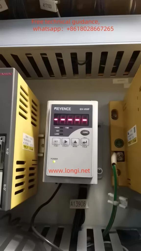
The KEYENCE EX-V series controllers are high-speed, high-precision digital displacement sensors widely used in industrial automation. Their panel design is intuitive and straightforward, offering powerful functionality. The main function keys on the panel include:

- SET key: Enters the parameter setting mode.
- CALL key: Calls up stored tolerance limit values.
- HIGH, LOW, GO keys: Used to set tolerance limit values.
- ZERO key: Quickly resets the display value to “0000”.
- FUNC key: Selects different functional modes.
- UTILITY key: Enters the utility menu for advanced settings.
- CALIB key: Calibrates the sensor.
Initializing Parameters
Initializing parameters refers to restoring the controller to its factory settings. This can be done through the following steps:
- Press and hold the SET key for at least 2 seconds to enter the common function selection mode.
- Use the HIGH or LOW keys to select the “E” function (initialization).
- Press the SET key to enter the initialization settings.
- Press the SET key again to confirm initialization, and the controller will restart and restore to factory settings.

Basic Mode Operation
The EX-V series controllers support multiple measurement modes, such as bottom dead center mode, eccentricity/vibration mode, thickness/gap mode, etc. The following example demonstrates how to set the bottom dead center mode:
- Press the SET key to enter the tolerance limit setting mode.
- Use the HIGH or LOW keys to select the “bottom dead center mode”.
- Press the SET key to enter the specific settings for this mode.
- Follow the prompts to set the upper limit, lower limit, and reference values.
- Press the SET key again to save the settings.

II. Common Function Setting Procedures and Data Processing Functions
Common Function Setting Procedures
Common functions include display scaling, monitoring output settings, digit/decimal point settings, offset value settings, output mode selection, panel lock, etc. The setting procedures are as follows:
- Press and hold the SET key for at least 2 seconds to enter the common function selection mode.
- Use the HIGH or LOW keys to select the desired function number (e.g., “E” for initialization, “F” for monitoring output settings, etc.).
- Press the SET key to enter the specific settings for that function.
- Make the required settings according to the prompts, and press the SET key again to save.
Data Processing Functions
The EX-V series controllers offer rich data processing functions, such as average measurement count and average measurement time settings, digital filter settings, etc. The following example demonstrates how to set the average measurement count:
- Enter the common function selection mode.
- Select the “average measurement count” function.
- Use the HIGH or LOW keys to select the desired average measurement count (e.g., A-A5 represents 64 averages).
- Press the SET key to save the setting.
III. Fault Codes and Their Handling Methods
The EX-V series controllers have a comprehensive fault diagnosis function. When a fault occurs, the corresponding fault code will be displayed on the screen. Common fault codes, their meanings, and handling methods are as follows:
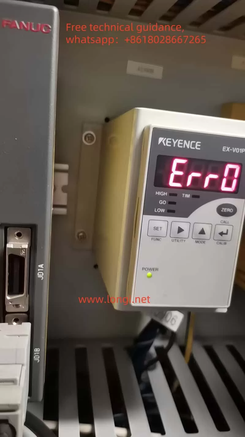
- Err0: Indicates no fault, but the sensor may not be functioning properly due to other reasons. Check if the sensor head is installed correctly, if the connecting cable is intact, and if the working environment meets the requirements.
- Err1: Indicates that the upper limit setting value is less than the lower limit setting value plus the tolerance distance. Adjust the upper and lower limit settings accordingly.
- Err2: Indicates that the input value exceeds the settable range. Check the input value and reset it.
- Err3: Indicates that the monitoring output setting value exceeds the range. Readjust the monitoring output settings.
IV. Detailed Analysis and Handling of ERR0 Fault
Meaning of ERR0 Fault
The ERR0 fault code in EX-V series controllers does not indicate a hardware or software fault but rather a status indication that the sensor may not be functioning properly due to non-fault factors. For example, improper installation of the sensor head, loose or damaged connecting cables, or an unsuitable working environment may trigger the ERR0 fault.
Handling Methods
- Check Sensor Head Installation: Ensure that the sensor head is correctly installed on the mounting bracket and securely fastened.
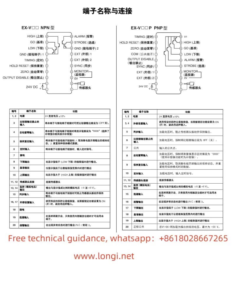
- Check Connecting Cables: Inspect the connecting cables for damage and ensure they are securely connected. Replace or reconnect any damaged or loose cables.
- Check Working Environment: Ensure that the working environment meets the EX-V series controller’s requirements, such as temperature, humidity, and vibration levels.
- Restart the Controller: After addressing the above issues, attempt to restart the controller to restore normal operation.
Repair Suggestions
If the ERR0 fault persists after following the above steps, it is recommended to contact KEYENCE’s after-sales service center for professional repair. Before repair, ensure that all important parameters and settings are backed up to facilitate quick restoration after repair.
V. Conclusion
The KEYENCE EX-V series controllers, as high-performance digital displacement sensors, play a crucial role in industrial automation. Through this article, readers can understand the panel functions, basic operations, common function setting procedures, data processing functions, and fault code handling methods of these controllers. In particular, the detailed analysis and handling suggestions for the ERR0 fault will help users quickly identify and effectively resolve issues.
