I. Introduction to the Operating Panel Functions and Basic Settings
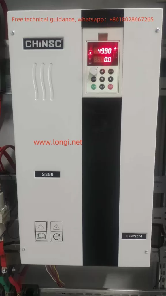
The CHINSC S350N series of inverters feature a comprehensive operating panel that provides functions such as operation monitoring, parameter modification, and fault alarm. Here are some basic functions and setting methods of the operating panel:

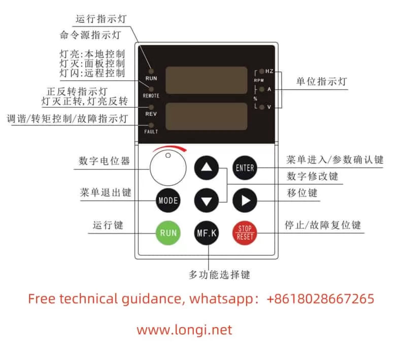
- Operating Panel Function Introduction
- RUN Indicator Light: Off indicates that the inverter is stopped, and on indicates that the inverter is running.
- REMOT Indicator Light: Off represents keyboard operation control, on represents terminal operation control, and flashing indicates remote communication operation control.
- REV Indicator Light: On indicates that the inverter is in reverse operation.
- FAULT Indicator Light: Slow flashing indicates the tuning state, and fast flashing indicates a fault state.
- Setting and Eliminating Passwords
- Setting Password: Modify the function code H7-03 to set a password. Setting H7-03 to a non-zero value will establish a user password. After setting, pressing the ENTER key in the normal interface will prompt for the correct password to proceed with parameter settings.
- Eliminating Password: After correctly entering the password, set H7-03 to 0 to eliminate the password.
- Parameter Initialization
- Use function code HP-01 for parameter initialization. Selecting HP-01 as 01 will restore factory parameters (excluding motor parameters); selecting 02 will clear recorded information; selecting 03 will restore all factory parameters.
- Locking Keyboard Parameters
- Use function code HP-04 to lock parameters. Setting HP-04 to 1 will make all parameters except this one readable but not writable, enabling parameter locking.

II. Terminal Forward/Reverse Control and External Potentiometer Speed Regulation
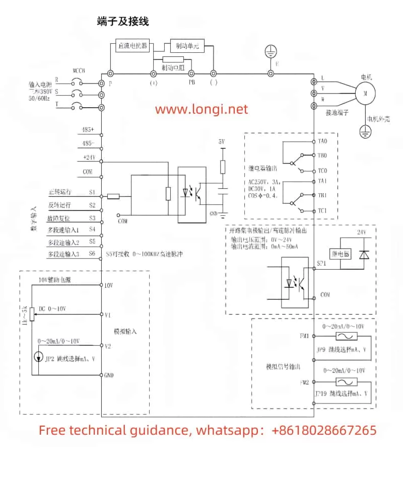
The CHINSC S350N series of inverters supports multiple control methods, including terminal forward/reverse control and external potentiometer speed regulation. Here are the specific wiring and parameter setting methods:
- Terminal Forward/Reverse Control
- Terminals to Wire: Connect the forward control to terminal S1, reverse control to terminal S2, and the common terminal to COM.
- Parameter Settings:
- Set H0-13 to 0 (two-wire mode 1), H4-00 to 1 (S1 for forward operation), and H4-01 to 2 (S2 for reverse operation).
- Or set H0-13 to 1 (two-wire mode 2), H4-00 to 1 (S1 for operation enable), and H4-01 to 2 (S2 for operation direction).
- External Potentiometer Speed Regulation
- Terminals to Wire: Connect the external potentiometer to terminals V1 and GND.
- Parameter Settings:
- Set H0-00 to 2 (V1), indicating that the main frequency source A is the external potentiometer input.
- Adjust H0-08 (digital frequency setting) and other related parameters as needed.
III. Fault Codes and Solutions
The CHINSC S350N series of inverters comes with comprehensive fault diagnosis capabilities. Here are some common fault codes, their possible causes, and solutions:
- E001 – Inverter Unit Protection
- Possible Causes: Short circuit in the inverter output circuit, excessive wiring length between the motor and inverter, loose internal wiring of the inverter, or abnormal main control board.
- Solution: Eliminate external faults, install reactors or output filters, securely connect all wires, or replace the circuit board.
- E002 – Acceleration Overcurrent
- Possible Causes: Too short acceleration time, vector control mode without parameter identification, inappropriate manual torque boost or V/F curve.
- Solution: Increase the acceleration time, perform motor parameter identification, or adjust the manual torque boost or V/F curve.
- E003 – Deceleration Overcurrent
- Possible Causes: Too short deceleration time, vector control mode without parameter identification, sudden load increase during deceleration.
- Solution: Increase the deceleration time, perform motor parameter identification, or eliminate sudden load increases.
- E004 – Constant Speed Overcurrent
- Possible Causes: Vector control mode without parameter identification, sudden load increase during operation, or undersized inverter selection.
- Solution: Perform motor parameter identification, eliminate sudden load increases, or select an inverter with a higher power rating.
- E010 – Inverter Overload
- Possible Causes: Excessive load or motor stall, or undersized inverter selection.
- Solution: Reduce the load and check the motor and mechanical conditions, or select an inverter with a higher power rating.
- E015 – External Device Fault
- Possible Cause: External fault signal input through multifunction terminal S.
- Solution: Reset the operation.

IV. Conclusion
The CHINSC S350N series inverter user manual provides detailed operation guidance and fault troubleshooting methods. By understanding the functions of the operating panel, mastering parameter setting methods, familiarizing oneself with terminal wiring, and fault codes, users can better use and maintain the inverter, ensuring its stable operation. In practical applications, users should flexibly adjust parameter settings according to specific situations, promptly troubleshoot and resolve faults, thereby improving production efficiency and equipment reliability.
